
The number of basic figures defined in the system is limited in order to keep storage requirements to a reasonable size. They fall, basically, into four classes. The first group consists of simple geometric shapes such as circles, triangles, rectangles, crosses. The second consists of more complex shapes which are frequently required. These include arrows, clocks and sine waves. The third class consists of electrical circuit symbols which are not of general interest. These include meters, transistors, resistors and capacitors. They reflect the fact that this work originated in an electrical engineering department. The fourth class is a set of alphanumeric characters of variable size which can be added to a picture at any position.
Before going into the details of the CAMP commands, an example of a complete program ready to run on Atlas will be given. Jobs will normally be punched on cards in the standard Atlas card code. Each program consists of the following:
A standard job description follows which suffice for most CAMP jobs:
JOB E1111 BLOGGS EXAMPLE 1
COMPUTING 30 SECONDS
TAPE 99 N0012FRAH4*INHIBIT
OUTPUT 0 LINEPRINTER 1000 LINES
OUTPUT 12 LINEPRINTER 50 LINES
OUTPUT 13 LINEPRINTER 50 LINES
TAPE IBM 14COMMON/SC/BLOGGS
STORE 60/60 BLOCKS
COMPILER LOAD
001/CAMP
Longer running jobs will of course require a greater computing time than the 30 seconds requested here. However, it is possible for the CAMP system to come off with the diagnostic
C TIME EXCEEDED
when an incorrect CAMP command has been read. As CAMP commands are printed once they have been obeyed, it is useful to examine the command immediately following the last one printed to see if an error occurs in its format. Full delails of Atlas job descriptions are given in the Atlas User's Handbook.
The job number, name and title are, only an example and should be replaced by the user's own. Similarly the name BLOGGS in the tape command should be replaced by the use name.
The data cards following are standard and therefore if the user wishes to run more than one CAMP job at a time it is possible to duplicate these cards to save re-punching.
CAMRA    3
DRAW 1
FRAME
ERASE1
DRAW 2
FRAME
ERASE2
DRAW 3
FRAME
ERASE3
LETER1  1                                                   BLOGGS
DRAW 1
FRAME
ERASE1
CAMRA    2
The command names must be left-adjusted, i.e. start in column 1. The users name must be left-adjusted in column 61 and must not be more than 12 characters in length including spaces. This is used for identification purposes. The command CAMRA 2 causes the output to be on hardcopy. CAMRA 1 would produce microfilm and CAMRA 3 produces both. The second 1 in the LETER command must be right adjusted as must all array numbers.
The following is an example set of CAMP commands with the picture it produced (Fig. 1).
12345678901234567890123456789012345678901234567890123456789012345678901234567890
C                                                           STICK TEST
C                                                           TESTING STICK FIGURE
ERASE1  0                                                   CLEAR STACK 1
MULTV    1 0.       0.        0.                            CLEAR VARIABLE 1
ADDV     1 6.0      0.        0.        0.
SETCV1  1  901.     8.0       7.0       8.                  SET UP HEAD
EXPAR1  1  7.0      6.        5.0       6.
EXPAR1  1  5.0      8.        6.0       8.
SETLN1  1  6.0      6.        6.0       2.                  BODY
EXPAR1  1  6.0      2.        4.0       0.                  LEGS
EXPAR1  1  6.0      2.        8.0       0.
SETLN1  1  4.0      4.        8.0       4.                  ARMS
CIRCL1  20 8.       5.        1.
RECT 1  3  3.5      4.        1.        1.
TRNGL1  4  5.75     6.5       0.5       0.5
CROSS1  5  5.5      7.25      0.25
CROSS1  6  6.25     7.25      0.25
ARROW1  7010.45     6.25      11.45     7.75      .4
ARROW1  8110.45     6.25      9.45      7.75      .6
ARROW1  9210.45     6.25      11.45     4.75      .7
ARROW1 10310.45     6.25      9.45      4.75      .5
CLOCK1 11  2.05     2.05      1.45      8.25
SINWV1 12  0.25     7.25      1.25      540.      3.
TRANS1 133 9.75     3.05      1.5
CAP  1 14  9.75     0.75      0.3
RESIS1 15  7.05     3.05      2.5
GRND 1 16  7.05     3.05      1.5
METER1 17  1.45     4.75      1.0       0.15
DRAW 1  0                                                   PLOT A STICK
FRAME                                                       RESET X-AXIS
This is the command STOP in columns 1 to 4 of a card. It causes the magnetic tape for the SC4020 plotter to be correctly terminated.
This is the standard ATLAS job terminator consisting of a card having a 7/8 multipunch in column 1 and the rest blank.
In CAMP all X and Y values used in defining a visible picture should be within the limits 0 ≤ X ≤12 and 0 ≤Y ≤9. The SC4020 is capable of resolving points to the second decimal place so that it is not sensible to have an increment smaller than 0.01. Restricting plotting within the X and Y ranges ensures that plotting lies within the normal cine frame on the film. It is possible to produce output for Y values in the range -1.5 ≤ Y ≤ 10.5 but the extended Y values will be outside the standard cine image. X or Y values outside the limits 0 ≤ X ≤ 12 and -1.5 ≤ Y ≤ 10.5 will be automatically scissored by the CAMP system. There is no restriction to using X or Y values outside these ranges. It is just that they will not be visible. (This is sometimes useful when doing zooms and wipes).
All commands must be entered by means of data cards. The column assignment is as follows:
Column(s) Entry
1-5       Command name
6         Stack number
7-9       Array number (right justified), or variable number
10        Figure parameter (if required)
12-20     Argument 1 or variable number
21-30     Argument 2 or variable number
31-40     Argument 3 or variable number
41-50     Argument 4 or variable number
51-60     Argument 5 or variable number
61-80     Comments
Arguments 1-5 can be placed anywhere within the columns allotted, provided a decimal point is included. A blank argument is read as zero. The array number must be right justified; i.e. the units digit of the array number must appear in column 9.
It is strongly suggested when key punching the cards that a program drum card be used to eliminate column position errors (using an 026 or 029 card punch):
Columns  Character punched
1-61     1
2-5      A
7-11
13-20
22-30    Plus punch (12 zone punch)
32-40
42-50
52-60
The list of commands is comprised of 4 basic classes. Class 1 commands set up a figure in an array. The figure must be loaded into an array before it can be drawn. Class 2 commands manipulate the co-ordinates of an array in some way. Once these commands are invoked, the original array is, of course, destroyed. If it is desired to save these values, they should be transferred into a new array and operated upon there. Class 3 commands perform arithmetic operations upon the 8 variables and define instruction loops. Class 4 commands deal with the plotter itself.
Comments may be placed on every card from columns 61-80. However, a special card may be devoted to this purpose by simply putting a C in column 1, and comments in columns 61-80. Blank commands are ignored. An invalid command ends the program and causes an error message to be printed. All cards are printed out on the users computer output in the order in which they are executed. This is quite helpful when debugging a sequence of commands for a picture.
A complete list of the commands available in the CAMP system on Atlas is given later. These must always be punched in the format described above. In the test that follows, a less exact format is used with spaces separating the individual fields. A parameter that is not applicable to the command being described is replaced by an asterisk. For example:
TRNGL S ARR * X Y BASE HGT
This would indicate that the command TRNGL does not require the figure parameter to be used. Note also that argument 5 is not printed as it is not required.
The S and ARR variables always refer to the stack and array to which the picture is being defined.
CIRCL S ARR D X Y RAD (Fig. 2)
defines a rectangle centred at (X,Y) with radius RAD. If D = 0 then the circle is solid. If D = 1 the circle will be dashed. The circle is always made up of exactly 36 line segments independent of the size of the circle.
RECT S ARR * X Y LNGTH HGT (Fig. 3)
defines a rectangle with the lower left corner at (X,Y) of length, LNGTH, and height, HGT.
TRNGL S ARR * X Y BASE HGT (Fig. 4)
defines an isosceles triangle with the lower left edge at (X,Y) of base, BASE and height HGT.
ARROW S ARR P X1 Y1 X2 Y2 HEAD (Fig. 5)
defines an arrow directed from (X1,Y1) to (X2,Y2) whose head is of size HEAD. The parameter P takes values between 0 and 3 and defines whether the shaft of the arrow is broken and the form of the tip. The four possibilities are shown in the diagram.
GRID S ARR * XDIV YDIV (Fig. 6)
defines a border around the 12 × 9 visible picture area and divides this by additional lines into XDIV equally spaced divisions in the X direction and YDIV equally spaced divisions in the Y direction.
CROSS S ARR * X Y SIDE (Fig. 7)
defines a cross with the lower left edge at (X,Y) of width and height equal to SIDE.
CLOCK S ARR * X Y RAD TIME (Fig. 8)
defines a clock centred at (X,Y) with radius RAD showing time TIME where the integer part of TIME defines the hour and the fractional part is the decimal fraction of an hour.
SINWV S ARR * X Y AMP DEG LNGTH (Fig. 9)
defines a sine wave with origin at (X,Y). The length of the wave is LNGTH and amplitude AMP The sine wave extends from 0 to DEG degrees.
CAPP S ARR * X Y DIST (Fig. 10)
defines a capacitor with centre of left plate at (X,Y) and plate separation of DIST.
RESIS S ARR * X Y LNGTH (Fig. 11)
defines a resistor whose left edge is at (X,Y) and is of length, LNGTH.
GRND S ARR * X Y DIST {Fig. 12)
defines an earth symbol (or ground) with a connection at (X,Y) of length and height, DIST.
TRANS S ARR P X Y DIST (Fig. 13)
defines a transistor with the left hand contact at (X,Y). The picture defines the variations produced by the arguments P and DIST.
METER S ARR * X Y RAD PICT (Fig. 14)
defines a meter centred at (X,Y) of radius RAD whose dial indicates PCT as the fraction of full scale reading.
So far we have described the basic figures available to the CAMP user. In general these will not be sufficient to define all that the user requires. Consequently three additional commands are provided for defining arrays as a set of lines.
SETCV S ARR * X1 Y1 X2 Y2
defines the first two points of an array plotted as a closed curve.
SETLN S ARR * X1 Y2 X2 Y2
defines the first two points of an array plotted as a series of unjoined lines.
EXPAR S ARR * X1, Y1, X2 Y2
expands a previously defined SETCV or SETLN array by adding two more points onto the end. The EXPAR command can be used as many times as desired. However, it should only expand the array which is currently at the end of the stack. If an odd number of points is to be placed in a closed curve array (one started by SETCV) then it is necessary to set both points equal in the last EXPAR command, i.e. X2=X1 and Y2=Y1.
Once the user has obeyed the standard set of commands required at the head of each program (described earlier) all stacks should be empty except stacks 7 and 8. Stack 7 contains the definitions of the character set on the assumption that they are to appear in the area 0 ≤ X,Y ≤ 1. Commands will be described later for producing text of a specified size at any position on the plotting area. If the user wishes to produce textual output then he must be careful not to use stack 7. Full details of the character set and equivalent array numbers are given later.
Stack 8, array 1 contains a rectangle which borders the cine frame.
This set of commands is designed to manipulate and change the contents of arrays and stacks.
ERASE S ARR
this clears a particular array to all zeros. If the array is the last defined in stack S then the space is reclaimed and can be used again. If ARR is zero, the entire stack is set to zero. It is good practice to start each frame or sequence with ERASEed stacks to avoid any carry over from previous frames.
ROTAT S ARR * X Y ANG
rotates an array about the point (X,Y) by ANG degrees. If ANG is positive then rotation is anti clockwise. If ARR is zero then the whole stack is rotated. Each X and Y value in the specified array or stack is replaced by its rotated value. Cumulative rotations can cause build up of rounding error so that the picture disintegrates. It is good practice, therefore, to reinitialise pictures where possible to avoid this.
OFSET S ARR * DX DY
offsets an array by DX in the X direction and DY in the Y direction. DX and DY can be either positive or negative. If ARR is zero then the entire stack is offset.
SIZE S ARR * XREF YREF XMAG YMAG
expands or contracts all points of an array about the reference point (XREF,YREF). New coordinates of all X,Y values in the array are computed by the following relations:
X' = (X - XREF} * XMAG + XREF
Y' = (Y - YREF) * YMAG + YREF
where (X,Y) are the original co-ordinates of any point in the array. If XMAG and YMAG are greater than 1, the points expand about the reference point; if XMAG and YMAG are less than 1, the points contract about the reference point; if XMAG and YMAG equal 1 then the points are unchanged; if XMAG and YMAG equal zero then all points are set equal to the reference point. As long as XMAG and YMAG are equal, the picture merely changes its size without being distorted. If ARR is zero, the entire stack is affected.
MOVE STA ARRA * STB ARRB
This command is used with a DO LOOP (to be described later) to move in equal increments, a figure whose initial position is stored in stack STA, array ARRA, to a final position which is stored in stack STB, array ARRB. If both ARRA and ARRB are zero, the entire stack is moved. The parameter NTIMES from the DO instruction determines the total number of equal increments used. The contents of stack STA, array ARRA contain their original values the first time through the loop. For each time through the contents are changed by the MOVE command until, at the end of the loop, stack STA, array ARRA contains the contents of STB, array ARRB. The contents of stack STB, array ARRB will have been destroyed at the end of the loop.
Consider, for example, a film requiring an arrow to drift across the screen in 2 seconds (assume 24 frames per second):
ARROW  1  1  P  X1  Y1  X2  Y2  HEAD
ARROW  1  2  P  X1  Y1  X2  Y2  HEAD
DO              48
MOVE   1  1     1   2
DRAW   1  1     0
FRAME
LOOP
TNSFR SB ARRB P P1 P2 SA ARRA BPT1
transfers points P1 to P2 inclusive from an array ARRA, stack SA into array ARRB, stack SB. Point P of array ARRA will begin loading into array ARRB starting at point BPT1. If BPT1 is left blank or set to zero then it is assumed to have the value 1. If P is:
ARRB      0,  both X and Y co-ordinates are transferred
new       1,  only X co-ordinates are transferred
          2,  only Y co-ordinates are transferred

ARRB      3,  both X and Y co-ordinates are transferred
already   4,  only X co-ordinates are transferred
exists    5,  only Y co-ordinates are transferred

          9,  both X and Y co-ordinates are transferred until either all
              the points PI to P2 are transferred, or until the end of
              array ARRA is reached, whichever occurs first.
              This allows a user to insert a large value to P2 if the
              actual length of array ARRA is not known.
For example:
SETLN   1  1    1.0   2.0   3.0   4.0
SETLN   1  2    5.0   6.0   7.0   8.0
TNSFR   1  24   2.0   2.0   1.0   1.0   1.0
is equivalent to defining array 2 as
SETLN   1  2    3.0   6.0   7.0   8.0
DUMP S
As a debugging aid, it is possible to print the contents of the 1000 locations of stack S using this command.
POINT S ARR * X Y PT
This replaces the PTth point of array ARR, stack S with the new point (X,Y). Array ARR should already be defined.
LETER S ARR * * * * * * TEXT
Individual characters may be defined by transferring the contents of the corresponding array in stack 7 into stack S array ARR. The number of points in each character is defined below. This does become tedious if a large number of characters in a textual string is to be transferred. The LETER command loads up to 20 characters of TEXT into stack S starting with array ARR. Each character is embedded in a 1 × 1 square (which includes a small inter-character gap) and resides in a separate array of stack 7.
The text to be transferred is placed in the last 20 columns of the card (usually reserved for comments in other commands). If fewer than 20 characters are to be transferred, then the string of text should be terminated by the character > (the symbol # is the terminator on the 360 version). The text is loaded into stack S starting in array ARR, with each new character placed into the next consecutive array and offset an inch to the right of the previous one. The first character is located with the lower left hand corner (ARR-1) units to the right of the origin, with the others following it at 1 unit intervals in the X direction, A blank is considered a legal character. If more than 20 characters are required, LETER commands can be used consecutively to concatenate the strings of text.
Suppose we wish to plot a message 0.2 units high.
LETER1  1                                                   THE MEDIUM IS THE ME
LETER1 21                                                   SSAGE>
SIZE 1  0  0.0      0.0       0.2       0.2
DRAW 1  0  0.0
These commands would load 25 characters into stack 1 (arrays 1 to 26), reduce their height to 0.2 units and the total length to 5.2 and output the message starting at the origin.
So far we have implied that the arguments in the class 1 and 2 commands are constant values which define the action of the command. However, it is sometimes useful to be able to define a command which can vary in meaning.
CAMP defines a set of nine variables, V1 to V9, which can be set to any particular value or manipulated by the class 3 commands. It is possible to replace all arguments other than the stack and parameter arguments by one of the nine variables. Due to limitations in the FORTRAN input/output package (the language in which CAMP is written), it is not possible to write,for example, V1 in a CAMP command as only numbers are allowed. Most arguments should be small numbers. Therefore V1 to V9 are represented by the numbers 901.0 to 909.0. For example:
12345678901234567890123456789012345678901234567890
CIRCL1 10 4.0       4.0       3.0
defines a circle centred at (4.0,4.0) and radius 3.0.
12345678901234567890123456789012345678901234567890
CIRCL1 10 4.0       4.0       901.0
defines a circle centred at (4.0,4.0) and radius equal to the current value of the variable V1.
The introduction of variables does not, by itself, increase the flexibility of the system by much. However, there are class 3 commands which allow a set of commands to be repeated a number of times. If these commands depend on the current values of variables, it is possible to achieve quite complex picture manipulations with a few CAMP commands in a loop.
The class 3 commands have the general format:
CMND * * VAR OPRND BGIN END
The argument VAR is in the parameter field and therefore must be a single digit. This defines the particular variable to be used in the operation. A variable used in any other argument position will have the usual representation, i.e. the constants 901.0 to 909.0.
The two parameters BGIN and END decide whether or not this command is to be executed. If V9 is less than the value of BGIN then the command will not be executed. If END is not blank or zero then the command will only be executed if V9 is less than the value of END.
In general V9 is reserved to mean the loop variable. It is therefore sensible never to set V9 except when it is defined by a loop. The class 3 commands are as follows:
ADDV * * VAR OPRND BGIN END
places the contents of variable VAR plus OPRND into VAR
SUBV * * VAR OPRND BGIN END
places the contents of variable VAR minus OPRND into VAR
MULTV * * VAR OPRND BGIN END
places the contents of variable VAR times OPRND into VAR
DIVV * * VAR OPRND BGIN END
places the contents of variable VAR divided by OPRND into VAR
SINV * * VAR OPRND BGIN END
places the sine of OPRND degrees into variable VAR
COSV * * VAR OPRND BGIN END
places the cosine of OPRND degrees into variable VAR
SQRTV * * VAR OPRND BGIN END
places the square root of OPRND into variable VAR
EXPV * * VAR OPRND BGIN END
places eOPRND into variable VAR
DO * * * NTIMES
sets up a loop of commands to be repeated NTIMES iterations.
LOOP
defines the end of the group of commands starting with DO which comprise the loop. Loops cannot be nested, i.e. one must end before another begins.
On obeying the DO command initially, the variable V9 is set to 1. Each time the LOOP command is encountered, the value of V9 is increased by one and the commands immediately following the DO command are executed again. This continues until the value of V9 is equal to NTIMES when the LOOP command is encountered. In this case the next command obeyed is the one following the LOOP command.
DRAW S ARR * NODRW
The picture defined as array ARR of stack S is drawn as long as NODRW is blank or zero. If NODRW is non-zero the command is ignored. IF ARR is zero, the whole stack is drawn rather than the single array ARR.
MDRAW S ARR P LFT RGT BOT TOP
The picture defined as array ARR of stack S is drawn with the part of the picture defined interior to the rectangle LFT ≤ X ≤ RGT, BOT ≤ Y ≤ TOP being masked off. If ARR=0 the entire stack is drawn with masking. If the parameter P is 1, the lines defining the picture are scissored by the border of the cine frame (i.e. 0 ≤ X ≤ 12, 0 ≤ Y ≤ 9). This extra test is not performed if P is blank or zero.
WDRAW S ARR P LFT RGT BOT TOP
draws those parts of the lines in the picture defined as stack S, array ARR which fall within the rectangle window LFT ≤ X ≤ RGT, BOT ≤ Y ≤ TOP. If ARR-0 the whole stack is drawn under the same conditions. If the parameter P is 1, the last four arguments are assumed to be 0.0, 12.0, 0.0, 9.0 and can therefore be omitted.
SAVE
ESAVE
REPET * * * NTIMES
These three commands are used to store picture drawing SC4020 instructions which are to be repeated many times. They save a considerable amount of computing time. SAVE begins storing all drawing and frame advance instructions instead of performing them. Approximately 2500 lines can be saved. If this number is exceeded, an error message is printed, and the program stops. Each time SAVE is obeyed, the previously saved commands are destroyed.
The command ESAVE ends the saving process. Any further drawing or frame advance commands are obeyed rather than being saved.
The REPET command performs all the SC4020 instructions that have been stored for NTIMES. For example:
SAVE
DRAW  2  0  0.0
WDRAW 3  01
FRAME
ESAVE
REPET         48.0
will draw stack 2 and the part of stack 3 inside the 9 × 12 border of the cine frame for 48 frames. This is much more efficient than an equivalent set of commands using DO and LOOP.
Often several stacks of figures remain stationary while only one moves. To save processing time, the commands for outputting the stationary stacks and advancing the film should be stored and called once for each cycle of a DO LOOP For example:
SAVE
DRAW   1   0        0.0
DRAW   2   0        0.0
FRAME
ESAVE
DO         96.0
OFSET 3    0        0.1     0.1
WDRAW 3    01
REPET               1.0
LOOP
This set of commands saves the stationary figures in stacks 1 and 2 and the advance film. For each iteration, the figure in stack 3 is moved and then output with the stationary information on the next frame.
FRAME
This concludes the current frame of film and moves the film ready for output on the next frame.
STOP
stops the program.
CAMRA * * I
If I=1, the microfilm camera is selected for output.
If I=2, the hardcopy camera is selected for output.
If I=3, both cameras are selected together.
It is usual to debug films by outputtig selected frames on hardcopy in the early runs. When the bugs have been removed, the microfilm camera is selected.
The CAMPER system is very similar except that it is three-dimensional. The language allows the user to create, manipulate and plot three-dimensional figures onto a two-dimensional plane in true perspective. A similar but but distinct set of picture defining commands are provided. Many commands in CAMPER are either identical or a logical extension of the two-dimensional command in CAMP.
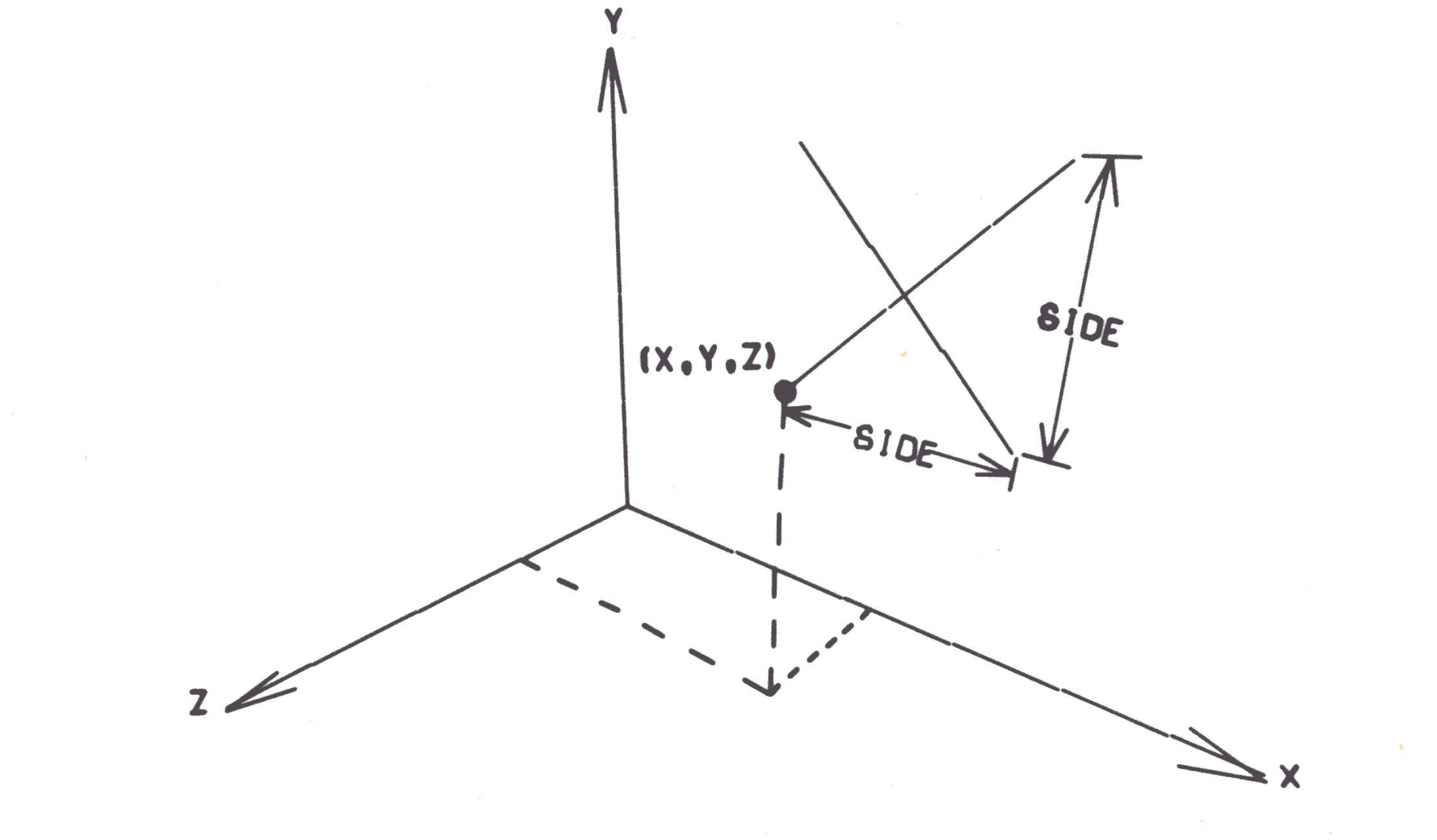
The user defines figures in an area 0 ≤ X ≤ 12, 0 ≤ Y ≤ 9, 0 ≤ Z ≤ 9. A viewing point of this scene is defined as the point (X,Y,Z). Alternatively, the viewing point can be defined in spherical ordinates as (OVER,UP,RAD). Both COVER and UP are given in degrees and RAD is the distance from the origin. A plane can be imagined perpendicular to the line from the viewing point to the origin. This plane is called the picture plane. The figure to be plotted normally lies on the opposite side of this plane. Visual arrays from the figure to the viewing point pierce the picture picture plane, tracing out a perspective drawing as it scans the figure. It is this projected view that is calculated by the computer and plotted. The user must define the distance he requires between the viewing point and picture plane. If the picture plane is moved towards the viewer, the image becomes proportionately smaller, and vice versa. The co-ordinates of the viewing point can be located in any of the eight octants, so that the figure can be observed from any possible position. Fig. 15 illustrates the geometry.
Before drawing a frame, there is still one parameter to be fixed and that is the part of the picture plane that will be viewed. Initially the perspective point on the picture plane equivalent to the three-dimensional is located at the ower left hand corner of the frame drawn, It is possible to change the part of the picture plane that is viewed by defining a new position for the three-dimensional origin.
The format of arrays in CAMPER is very similar to that of CAMP except that each (X,Y) is replaced by an (X,Y,Z). As in CAMP, stack 7 contains the definitions of the character font. The space required for each character is considerably larger in CAMPER due to each point requiring a Z co-ordinate. For this reason the CAMPER character set is a subset of the CAMP one (see below).
The stack 8 is initialized to contain the three axes: X=12, Y=9, Z=9 in arrays 1, 2 and 3.
The format of the card deck is almost identical to the CAMP one except that
001/CAMP
is replaced by
002/CAMPER
in the Job Description.
The standard data cards required to identify the output are as follows:
CAMRA
RDRAW  1  0.0   0.0   500.0   500.0
FRAME
ERASE1 1
RDRAW  2  0.0   0.0   500.0   500.0
FRAME
ERASE2
RDRAW  3  0.0   0.0   500.0   500.0
FRAME
ERASE3
LETER1 1                                BLOGGS
RDRAW  1  0.0   0.0   500.0   500.0
FRAME
ERASE1
CAMRA  2  2
The S and ARR variables always refer to the stack and array to which the picture is being defined.
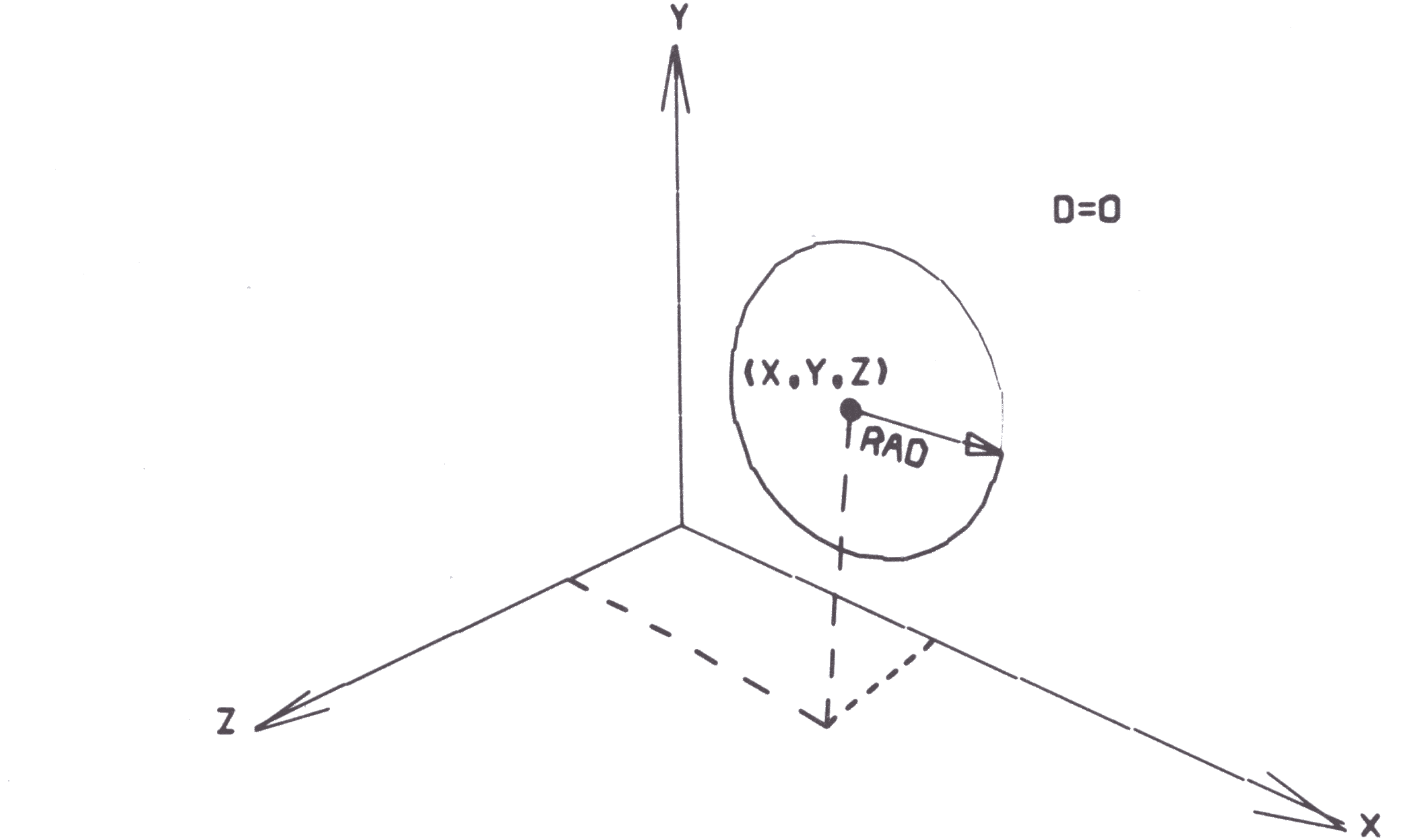
CIRCL S ARR D X Y Z RAD
defines a circle centred at (X,Y,Z) of radius RAD, in a plane parallel to the x-y plane. If D≠0, the circle is dashed. The array is comprised of 37 points, which produces 36 straight lines. The first point lies to the right of the centre, and successive points fall every 10 degrees counter clockwise around the circle. (Fig. 16).
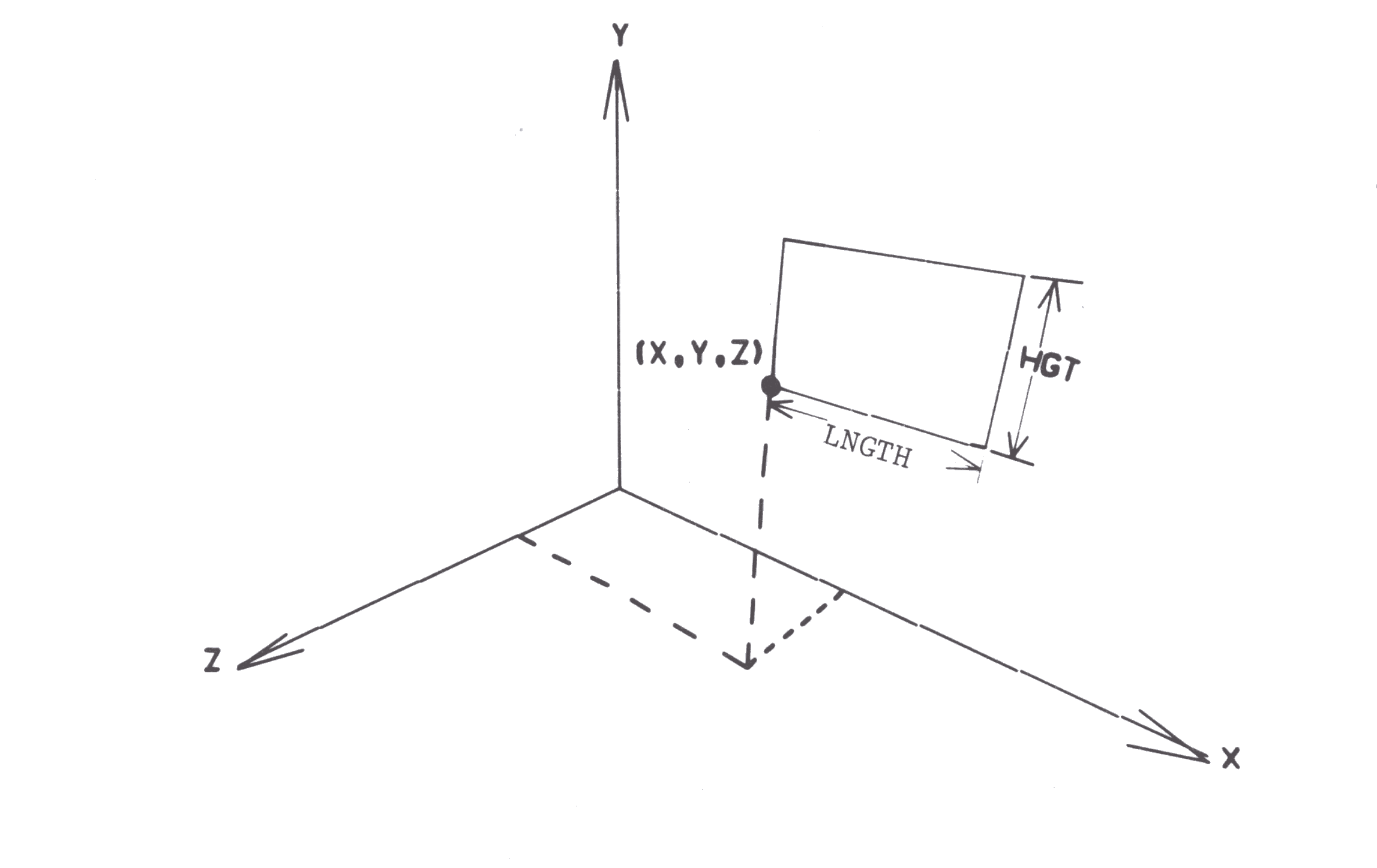
RECT S ARR * X Y Z LNGTH HGT
defines a rectangle with lower left hand corner at (X,Y,Z) of length, LNGTH and height HGT This figure lies in a plane parallel to the x-y plane. (Fig.17).
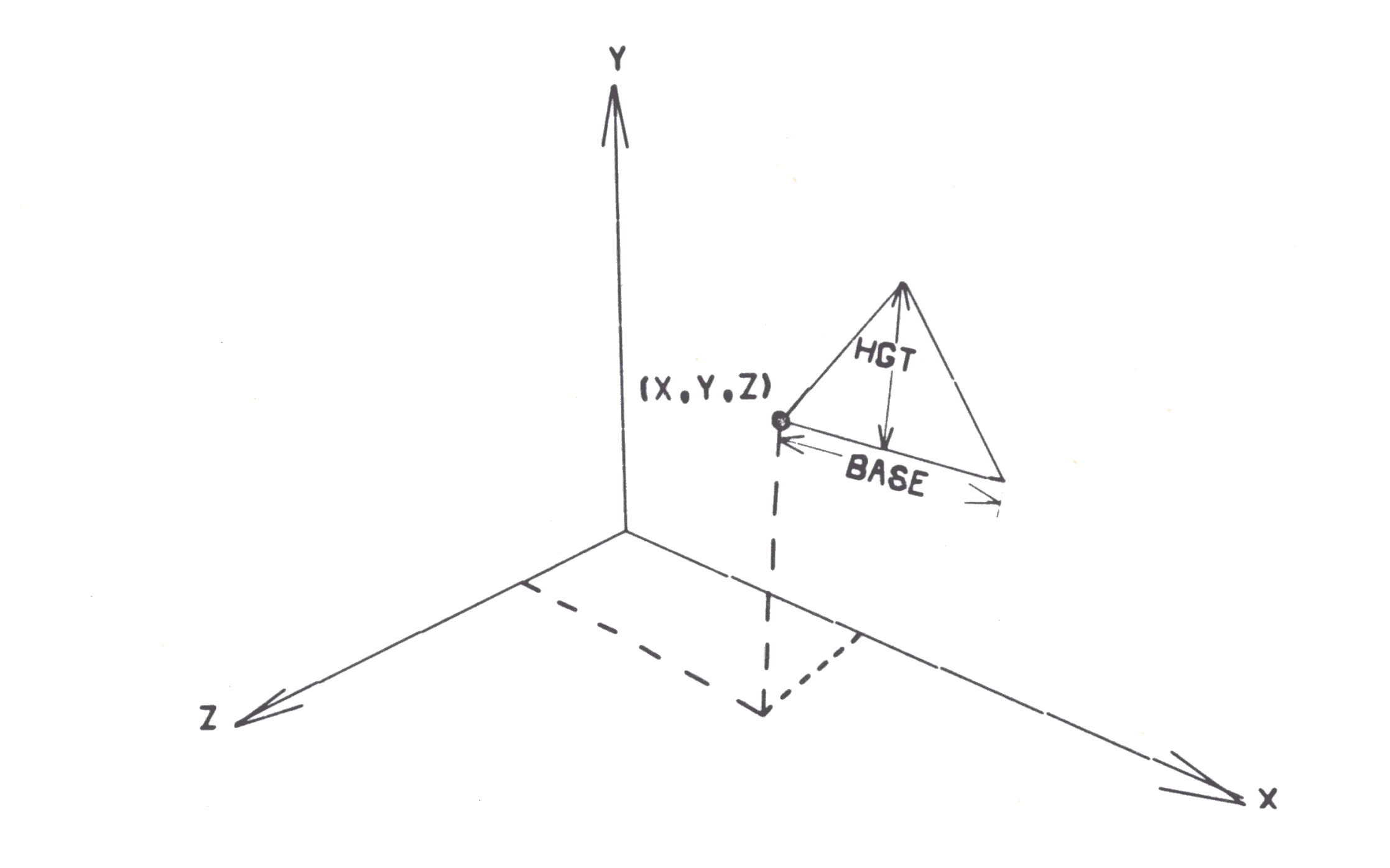
TRNGL S ARR * X Y Z BASE HGT
defines an isosceles triangle with the lower left corner at (X,Y,Z) of base, BASE and height, HGT. The figure lies in a plane parallel to the x-y plane. (Fig. 18).
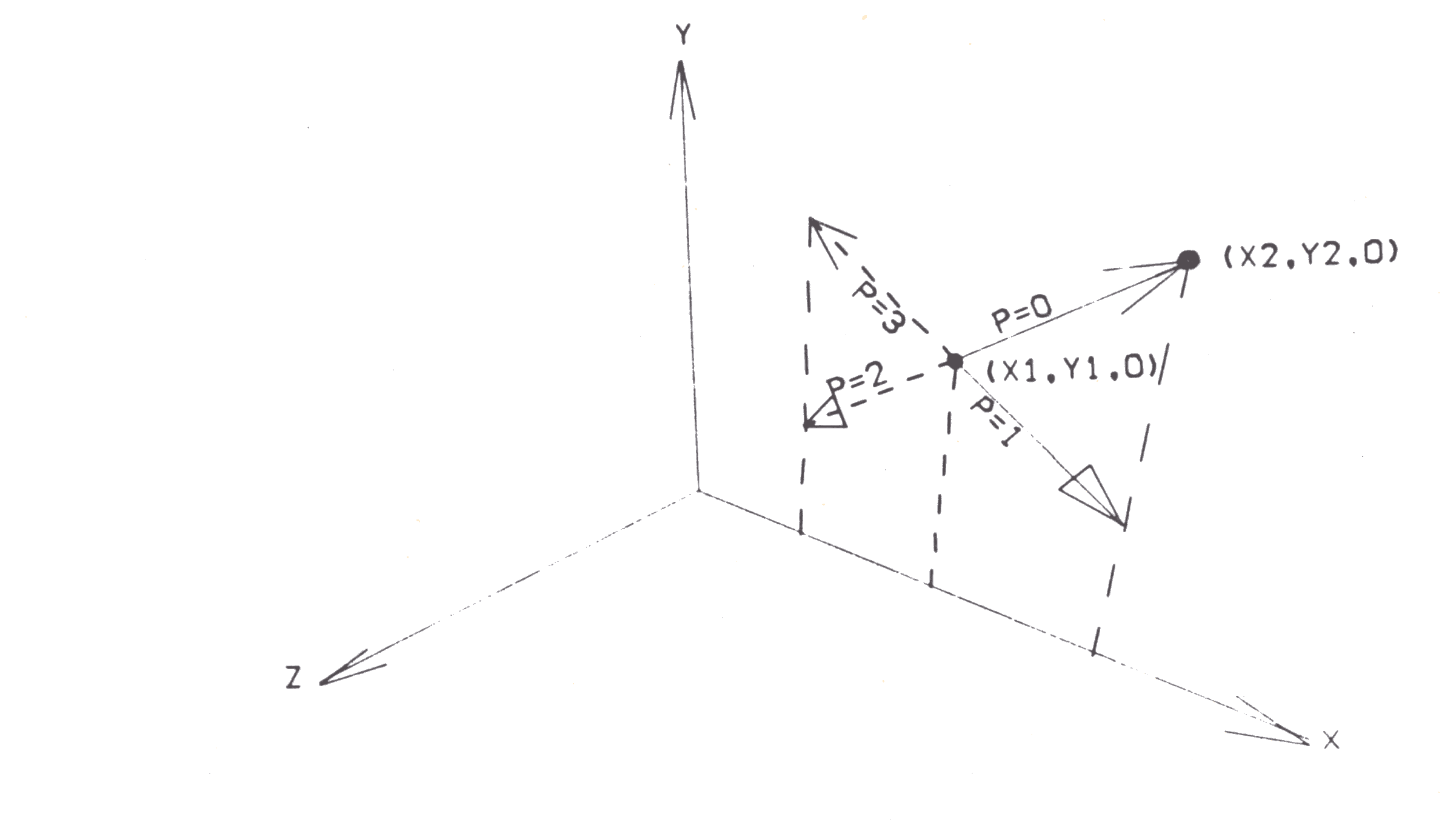
ARROW S ARR P X1 Y1 X2 Y2 HEAD
defines an arrow directed from (X1,Y1,0) to (X2,Y2,0) with a head of length, HEAD. The figure lies in the X-Y plane. The use of the parameter, P, is shown in the diagram.
CROSS S ARR * X Y ZSIDE
defines a cross with lower left hand corner at (X,Y,Z) of height and width SIDE. This figure lies in a plane parallel to the x-y plane. (Fig. 20).
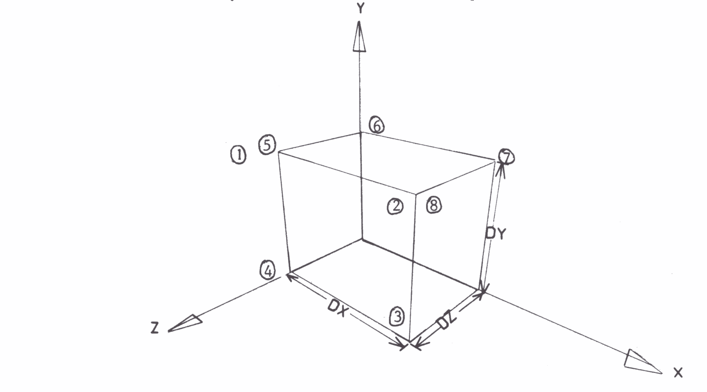
BOX S ARR * DX DY DZ
defines a box with one corner at the orgin and sides of length DX, DY and DZ in the positive X, Y and Z directions respectively. The order of points within the array is shown by the circled numbers in in the diagram. If only the top and the front of the box are required, the first 8 points should be transferred into a new array. No more than 8 points should be transferred from a box array. (Fig. 21).
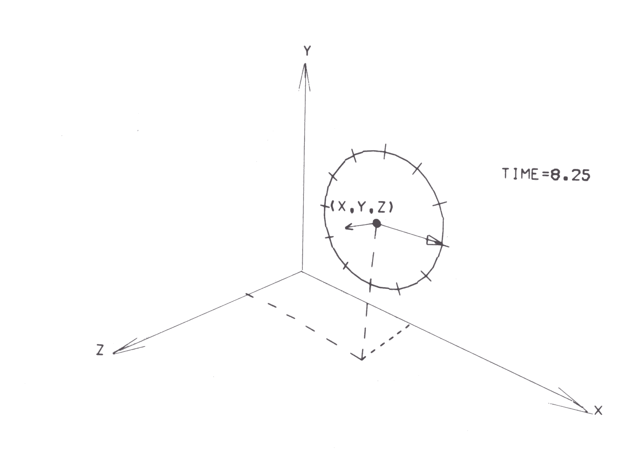
CLOCK S ARR * X Y Z RAD TIME
defines a clock face centred at (X,Y,Z) of radius RAD showing the time, TIME. The integer portion of TIME is the hour, and the fraction part is the decimal fraction of an hour. This figure lies in the plane parallel to the X-Y plane. (Fig. 22).
As in CAMP, additional figures can be defined out of lines.
SETCV S ARR * X Y Z
defines the first point (X,Y,Z) of a series of points to be connected consecutively by straight lines.
SETLN S ARR * X Y Z
defines the first point (X,Y,Z) of a series of pairs of points which represent a set of unconnected straight lines.
EXPAR S ARR * X Y Z
expands a previously defined SETCV or SETLN array by adding point (X,Y,Z) onto the end. EXPAR can be used as many times as desired, but it should only expand that array which is currently at the end of stack. SETCV should have at least one EXPAR command following it. SETLN should have an odd number of EXPAR commands following it to make sure that a complete set of pairs of points is defined.
C* * * * * * * * COMMENTS
defines a COMMENT in columns 61-80 which will be printed on the output. This is the only action of the command.
ERASE S ARR
erases the contents of array ARR of stack S. If ARR is blank or zero the whole stak is erased. This command should be used at the beginning of each new frame to avoid any carry over from the previous frame.
XYROT S ARR * X Y ANG
rotates array ARR of stack S about the line x=X, y=Y by ANG degrees. If ANG is positive the rotation is counter clockwise as the X-Y plane is viewed from the positive Z side. As the rotation is about a line perpendicular to the X-Y plane, the Z co-ordinates are not changed by this rotation. If ARR=0, the entire stack is rotated.
YZROT S ARR * Y Z ANG
rotates an array about the line y=Y, z=Z by ANG degrees. If ANG is positive, the rotation is counter clockwise as the Y-Z plane is viewed from the positive X side. As the rotation is about a line perpendicular to the Y-Z plane, the X co-ordinates are not changed by this rotation. If ARR=0, the entire stack is rotated.
XZROT S ARR * X Z ANG
rotates an array about the line x=X, z=Z by ANG degrees. If ANG is positive, the rotation is counter clockwise as the X-Z plane is viewed from the positive Y side. As the rotation is about a line perpendicular to the X-Z plane, the Y co-ordinates are not changed by this rotation. If ARR=0, the entire stack is rotated.
OFSET S ARR * DX DY DZ
offsets the points of the array ARR of stack S by DX, DY, DZ in the X,Y and Z directions respectively. DX, DY and DZ can be negative. If ARR=0, the entire stack is rotated.
SIZE S ARR * XREF YREF XMAG YMAG
expands or contracts all the points of the array, ARR of stack, S about the reference line, x= XREF, y=YREF New co-ordinates are computed by the following relations:
x' - (x-XREF) * XMAG + XREF
y' = (y-YREF) * YMAG + YREF
where (x,y) are the first two co-ordinates of a point in the array. If XMAG and YMAG are greater than one, the points expand about the reference line; if XMAG and YMAG are less than 1, the points contract about the reference line; if XMAG=YMAG=1, the points are unchanged. If XMAG=YMAG=0, all points are set onto the reference line. As long as XMAG and YMAG are equal, the picture merely changes its size without being distorted. If ARR=0, the entire stack is affected. The Z co-ordinates are unchanged by this command. To reduce or expand a figure in all three directions, use this in conjunction with ZSIZE.
ZSIZE S ARR * ZREF ZMAG
expands or contracts all the points of an array about the reference plane z=ZREF New Z coordinates are computed by the relation:
z' = (z-ZREF) * ZMAG + ZREF
where z is the third co-ordinate of a point in the array. ZMAG obeys the same properties as XMAG and YMAG do. To change the size of an array in three dimensions about the point (XREF, YREF, ZREF) use the SIZE command about x=XREF, y=YREF and the ZSIZE command about z= ZREF
MOVE STA ARRA * STB ARRB
This command is used within a DO LOOP to move in equal increments, a figure whose initial position is stored in stack STA, array ARR A, to a final position which is stored in stack STB, array ARRB.
If both ARRA and ARRB are zero, the entire stack is moved. The parameter NTIMES from the DO instruction determines the total number of equal increments used. After the loop is executed, the stack STA has been set equal to the original value of stack STB, and stack STB has been destroyed.
TNSFR SB ARRB P P1 P2 SA ARRA BPT1
transfers points P1 to P2 inclusively from array ARRA, stack SA into array ARRB, stack SB. Point P1 of array ARRA will begin loading into array ARRB, starting at point BPT1. If BPT1 is left blank or set to zero, it is assumed to be 1. If:
New        P = 0       all  three co-ordinates are transferred
array        = 1       only x-co-ordinates are transferred
ARRB         = 2       only y-co-ordinates are transferred
             = 3       only z-co-ordinates are transferred

ARRB         = 4       all  three co-ordinates are transferred
already      = 5       only x-co-ordinates are transferred
exists       = 6       only y-co-ordinates are transferred
only         = 7       only z-co-ordinates are transferred

             = 9       all co-ordinates of the points in array ARRB are transferred
                       from the given starting point to array ARRB until either all
                       the points P1 to P2 are transferred, or until the end of array
                       ARRA is reached, whichever occurs first. To transfer the whole
                       of an array of unknown size, a ficticiously high value of P2
                       can therefore be used.
POINT S ARR * X Y Z PT
replace the PTth point of array ARR of stack S with the new point (X,Y,Z). Array ARR should already have been set up.
DUMP S
prints the contents of the 1000 locations of stack S.
LETER S ARR ****** TEXT
adds up to 20 characters of TEXT into stack S, starting with array ARR. The text is placed in columns 61 onwards. If fewer than 20 characters are required, the > sign can be used to terminate the string. The text is then loaded into stack S, beginning in array ARR, with each new character placed into the next consecutive array and offset 1 unit in the positive x-direction. The first character is located with the lower left hand corner at (ARR-1, 0, 0) and the following characters at {ARR, 0, 0), (ARR+1, 0, 0) and so on. All characters lie in the X-Y plane (Z=0).
The CAMPER type 3 commands are identical to the CAMP type 3 commands.
RDRAW S ARR P X Y Z PP NODRW
SDRAW S ARR P OVER UP RAD PP NODRW
Both commands output the perspective trace of the picture contained in array ARR, stack S. If ARR=0, the entire stack is output. In RDRAW, the viewing point is given in Cartesian co-ordinates as (X,Y,Z). In SDRAW, the viewing point is given in spherical co-ordinates at OVER degrees from the Z-axis, UP degrees from the XZ plane and a radial distance of RAD from the origin.
The projection plane is located PP units from the viewing point, towards the origin. The figure to be plotted normally lies on the opposite side of the projection plane from the viewing point, since the projected image is then smaller than actual size. If the figure to be plotted lies between the projection plane and the viewing point, the plot will appear larger than actual size. As PP increases, the picture size is magnified, and vice versa. RAD and PP should always be positive. The angles OVER and UP can become negative, if desired.
If NODRW=Q, this command is executed while if NODRW=1 it is ignored. The value of NODRW is usually defined as a variable which changes its value around a loop to start or stop output of this picture.
The parameter P=1 will cause the perspective view of the figure to be tested at the outer border so that any portion of a line lying outside the 9 × 12 cine frame is not drawn. If P=0, no test is done. This feature is quite useful, since the programmer has no prior knowledge of whether the projected lines will spill out of the standard drawing rectangle.
If the solid figure lies within a 10 × 10 × 10 box, a good set of parameters for a 12 × 9 picture window would be OVER=45, UP=35, RAD=26, PP=12, or alternatively X=15, Y=15, Z=15, PP=12.
The geometry of the picture is given at the start of the CAMPER manual.
In the following commands, the 2-D origin referred to is the bottom left hand corner of the plotting area which is normally 12 × 9 in size. The 3-D origin is the location of the (0,0,0) point on the plotting area when the picture is output in perspective on the plotting area.
ORIGN * * * DIST
draws an L-shaped corner mark at the current 2-D origin of height and length, DIST. This is helpful in locating the origin of the frame.
BORDR
draws a 12 × 9 border around the plotting area where the lower left corner is the current 2-D origin. This can be used to frame a picture.
FRAME
This advances the film by one frame. A new frame is now available for output.
NUORG * * * X Y
This positions the 3-D origin X units over and Y units up from the current 2-D origin. X and Y may be negative if desired. This command is necessary to place the projected picture upon the centre of the plotting surface. Unless NUORG is called the 2-D and 3-D origins are at the same point. It is then likely that the part of the figure in the positive Z direction would spill off the bottom of the plotting area. A good set of values might be X=5, Y=4.
STOP
terminates the CAMPER program and outputs filemarks on the tape and generates statistics.
SAVE
ESAVE
REPET
CAMRA * * P
These commands are the same as for CAMP.
| Columns | 1-5 | 6 | 7-9 | 10 | 11-20 | 21-30 | 31-40 | 41-50 | 51-60 | 61-80 |
|---|---|---|---|---|---|---|---|---|---|---|
| Class | Name | Stack | Array | Par | Arg1 | Arg2 | Arg3 | Arg4 | Arg5 | Comments |
| 1 | CIRCL | S | ARR | D | X | Y | RAD | |||
| 1 | RECT | S | ARR | X | Y | LNGTH | HGT | |||
| 1 | TRNGL | S | ARR | X | Y | BASE | HGT | |||
| 1 | ARROW | S | ARR | P | X1 | Y1 | X2 | Y2 | HEAD | |
| 1 | SETCV | S | ARR | X1 | Y1 | X2 | Y2 | |||
| 1 | SETLN | S | ARR | X1 | Y1 | X2 | Y2 | |||
| 1 | EXPAR | S | ARR | X1 | Y1 | X2 | Y2 | |||
| 1 | GRID | S | ARR | XDIV | YDIV | |||||
| 1 | CROSS | S | ARR | X | Y | SIDE | ||||
| 1 | CLOCK | S | ARR | X | Y | Z | RAD | TIME | ||
| 1 | SINWV | S | ARR | X | Y | AMP | DEG | LNGTH | ||
| 1 | CAP | S | ARR | X | Y | DIST | ||||
| 1 | RESIS | S | ARR | X | Y | LNGTH | ||||
| 1 | GRND | S | ARR | X | Y | DIST | ||||
| 1 | TRANS | S | ARR | P | X | Y | DIST | |||
| 1 | METER | S | ARR | X | Y | RAD | PCT | |||
| 1 | FOR1 | S | ARR | P | A1 | A2 | A3 | A4 | A5 | |
| 1 | FOR2 | S | ARR | P | A1 | A2 | A3 | A4 | A5 | |
| 2 | C | COMMENTS | ||||||||
| 2 | ERASE | S | ARR | |||||||
| 2 | ROTAT | S | ARR | X | Y | ANG | ||||
| 2 | OFSET | S | ARR | DX | DY | |||||
| 2 | SIZE | S | ARR | XREF | YREF | XMAG | YMAG | |||
| 2 | MOVE | STA | ARRA | STB | ARRB | |||||
| 2 | TNSFR | SB | ARRB | P | P1 | P2 | SA | ARRA | BPT1 | |
| 2 | POINT | S | ARR | X | Y | PT | ||||
| 2 | LETER | S | ARR | TEXT | ||||||
| 3 | ADDV | VAR | OPRND | BGIN | END | |||||
| 3 | SUBV | VAR | OPRND | BGIN | END | |||||
| 3 | MULTV | VAR | OPRND | BGIN | END | |||||
| 3 | DIVV | VAR | OPRND | BGIN | END | |||||
| 3 | SINV | VAR | OPRND | BGIN | END | |||||
| 3 | COSV | VAR | OPRND | BGIN | END | |||||
| 3 | EXPV | VAR | OPRND | BGIN | END | |||||
| 3 | SQRTV | VAR | OPRND | BGIN | END | |||||
| 3 | DO | NTIMES | ||||||||
| 3 | LOOP | |||||||||
| 4 | DRAW | S | ARR | NODRW | ||||||
| 4 | MDRAW | S | ARR | P | LFT | RGT | BOT | TOP | ||
| 4 | WDRAW | S | ARR | P | LFT | RGT | BOT | TOP | ||
| 4 | SAVE | |||||||||
| 4 | ESAVE | |||||||||
| 4 | REPET | NTIMES | ||||||||
| 4 | FRAME | |||||||||
| 4 | STOP | |||||||||
| 4 | CAMRA | P |
The following characters are already defined in stack 7 when the CAMP or CAMPER is entered.
| Character | Array | No. of Pts | Character | Array | No. of Pts |
|---|---|---|---|---|---|
| A | 1 | 8 | Z | 26 | 4 |
| B | 2 | 12 | . | 27 | 6 |
| C | 3 | 8 | . | 28 | 6 |
| D | 4 | 8 | . | 29 | 2 |
| E | 5 | 8 | 0 | 30 | 10 |
| F | 6 | 8 | 1 | 31 | 6 |
| G | 7 | 10 | 2 | 32 | 8 |
| H | 8 | 6 | 3 | 33 | 14 |
| I | 9 | 6 | 4 | 34 | 6 |
| J | 10 | 12 | 5 | 35 | 10 |
| K | 11 | 6 | 6 | 36 | 12 |
| L | 12 | 4 | 7 | 37 | 4 |
| M | 13 | 6 | 8 | 38 | 16 |
| N | 14 | 4 | 9 | 39 | 12 |
| O | 15 | 10 | Space | 40 | 2 |
| P | 16 | 8 | + | 41 | 4 |
| Q | 17 | 12 | * | 42 | 8 |
| R | 18 | 14 | / | 43 | 2 |
| S | 19 | 14 | = | 44 | 4 |
| T | 20 | 4 | ( | 45 | 6 |
| U | 21 | 6 | ) | 46 | 6 |
| V | 22 | 4 | ' | 47 | 6 |
| W | 23 | 6 | ? | 48 | 22 |
| X | 24 | 4 | > Atlas | - | |
| Y | 25 | 6 | ≠ 360 | - | - |
| Z | > PDP15 | - | - |
. CAMP ONLY
49 For CAMP the termination character is the 49th whereas for CAMPER it is the 41st character
? is a multi-punch for Atlas
Figure                              Location

Circle                                 75
Circle (dashed)                        73
Cross                                   9
Triangle                                9
Rectangle                              11
Sine Wave                              75
Clock                                 150
Grid(DX,DY)                          4*(DX+DY)+9
Capacitor                              28
Resistor                               17
Transistor                            102
Meter                                 159
Ground                                 17
Arrow (Solid Tail, Open Head)          12
Arrow (Solid Tail, Closed Head)        14
Arrow (Dashed Tail, Open Head)         32
Arrow (Dashed Tail, Closed Head)       34
SETLN                                   5
SETCV                                   5
EXPAR (Each Use)                        4
Location 1        40000.
Locations 2-9     4 points
Location 1        30000.
Locations 2-9     4 points
Location 1        30000.
Locations 2-11    5 points
Location 1        30000. for solid,  40000. for dashed
Locations 2-73     36 points dashed
Locations 2-75     37 points solid
Location 1        40000.
Locations 2-5     2 points  solid line
Location 6        10000.
Location 7-12     3 points, open arrow head
Location 7-14     4 points, closed arrow head
Location 1        40000.
Locations 2-25    12 points, dashed line
Location 26       10000.
Location 27-32    3 points, open arrow head
Location 27-34    4 points, closed arrow head
Locations 1-75      Circle
Locations 76-89     Arrow (minutes)
Locations 90-101    Arrow (hour)
Location 102        20000.
Locations 103-150   24 points
Location 1        30000.
Locations 2-75    37 points
Location  1                    40000.
Locations 2- 4*(DX+DY) + 9     2*(DX+DY+2) Points
Location 1        30000.
Locations 2-17    8 points
Location 1        40000.
Locations 2-5     2 points
Location 6        10000.
Location 7-28     11 points
Location 1        40000.
Locations 2-17    8 points
Locations 1-14    Arrow
Location  15      20000.
Locations 16-27   6 points
Location  28-102  Circle
Locations 1-39       Half-circle
Locations 40-114     Circle
Locations 115-128    Arrow
Locations 129-137    Triangle
Location  138        10000.
Locations 139 -146   4 points
Location  147        20000.
Locations 148 -159   6 points
| Columns | 1-5 | 6 | 7-9 | 10 | 11-20 | 21-30 | 31-40 | 41-50 | 51-60 | 61-80 |
|---|---|---|---|---|---|---|---|---|---|---|
| Class | Name | Stack | Array | Par | Arg1 | Arg2 | Arg3 | Arg4 | Arg5 | Comments |
| 1 | CIRCL | S | ARR | D | X | Y | Z | RAD | ||
| 1 | RECT | S | ARR | X | Y | Z | LNGTH | HGT | ||
| 1 | TRNGL | S | ARR | X | Y | Z | BASE | HGT | ||
| 1 | ARROW | S | ARR | P | X1 | Y1 | X2 | Y2 | HEAD | |
| 1 | SETCV | S | ARR | X | Y | Z | ||||
| 1 | SETLN | S | ARR | X | Y | Z | ||||
| 1 | EXPAR | S | ARR | X | Y | Z | ||||
| 1 | CROSS | S | ARR | X | Y | Z | SIDE | |||
| 1 | BOX | S | ARR | D | DX | DY | DZ | RAD | ||
| 1 | CLOCK | S | ARR | X | Y | Z | RAD | TIME | ||
| 1 | FOR1 | S | ARR | P | A1 | A2 | A3 | A4 | A5 | |
| 1 | FOR2 | S | ARR | P | A1 | A2 | A3 | A4 | A5 | |
| 2 | C | COMMENTS | ||||||||
| 2 | ERASE | S | ARR | |||||||
| 2 | XYROT | S | ARR | X | Y | ANG | ||||
| 2 | XZROT | S | ARR | X | Z | ANG | ||||
| 2 | YZROT | S | ARR | Y | Z | ANG | ||||
| 2 | OFSET | S | ARR | DX | DY | DZ | ||||
| 2 | SIZE | S | ARR | XREF | YREF | XMAG | YMAG | |||
| 2 | ZSIZE | S | ARR | ZREF | ZMAG | |||||
| 2 | MOVE | STA | ARRA | STB | ARRB | |||||
| 2 | TNSFR | SB | ARRB | P | P1 | P2 | SA | ARRA | BPT1 | |
| 2 | POINT | S | ARR | X | Y | Z | PT | |||
| 2 | DUMP | S | ||||||||
| 2 | LETER | S | ARR | TEXT | ||||||
| 3 | ADDV | VAR | OPRND | BGIN | END | |||||
| 3 | SUBV | VAR | OPRND | BGIN | END | |||||
| 3 | MULTV | VAR | OPRND | BGIN | END | |||||
| 3 | DIVV | VAR | OPRND | BGIN | END | |||||
| 3 | SINV | VAR | OPRND | BGIN | END | |||||
| 3 | COSV | VAR | OPRND | BGIN | END | |||||
| 3 | EXPV | VAR | OPRND | BGIN | END | |||||
| 3 | SQRTV | VAR | OPRND | BGIN | END | |||||
| 3 | DO | NTIMES | ||||||||
| 3 | LOOP | |||||||||
| 4 | RDRAW | S | ARR | P | X | Y | Z | PP | NODRW | |
| 4 | SDRAW | S | ARR | P | OVER | UP | RAD | PP | NODRW | |
| 4 | ORIGN | DIST | ||||||||
| 4 | BORDR | |||||||||
| 4 | FRAME | X | Y | |||||||
| 4 | NUORG | X | Y | |||||||
| 4 | STOP | |||||||||
| 4 | SAVE | |||||||||
| 4 | ESAVE | |||||||||
| 4 | REPET | NTIMES | ||||||||
| 4 | CAMRA | P |
Figure                              Location

Circle                                112
Circle (dashed)                       109
Cross                                  13
Triangle                               13
Rectangle                              16
Box                                    51
Clock                                 222
Arrow (Solid Tail, Open Head)          17
Arrow (Solid Tail, Closed Head)        20
Arrow (Dashed Tail, Open Head)         47
Arrow (Dashed Tail, Closed Head)       50
Set Line Array (SETLN)                  4
Set Curve Array (SETCV)                 4
Expand Array (EXPAR)                    3 (each time used)
Suppose it is desired to depict 450° of a cosine wave. A sine wave must be set up, and the first 90° discarded. Since the sine wave is approximated by 36 straight lines connecting the points of the sine function evaluated every 15 degrees, 37 points are needed altogether. For the present example, 1 to 37 are needed. TNSFR is used with zero in column 10.
C
ERASE1  0
ERASE2  0
SINWV1  1  0.0      4.5       4.0       540.0     12.0
TNSFR2  10 1.0      37.0      1.0       1.0       1.0
OFSET2  1  -1.8     0.0
SETLN2  2  0.2      9.0       0.2       0.0
SETLN2  3  0.2      5.0       10.2      5.0
LETER2  4                                                   XY>
SIZE 2  4  3.0      0.0       0.2       0.2
SIZE 2  5  4.0      0.0       0.2       0.2
OFSET2  4  7.05     4.5
OFSET2  5  -3.8     7.8
LETER3  1                                                   Y=COS X>
OFSET3  0  2.5      5.0
SIZE 3  0  2.5      5.0       0.2       0.2
DRAW 2
DRAW 3
FRAME
A transistor circuit is shown below. A current source drives the base, an ammeter is in series with the emitter lead, and a voltmeter is connected from collector to emitter. This circuit was planned on a large piece of graph paper, and the SIZE instruction was used to reduce the scale before plotting. Notice that the left input terminal at (1.9,5.) is used as a reference point in the SIZE command. Hence this point remains stationary while the rest of the figure shrinks toward it. It is reduced once again and replotted 6.0 inches to the right.
C                                                           TRANSISTOR W METERS
ERASE1  0                                                    CLEAR STACK 1
CIRCL1  10 1.9      5.        .1                            LEFT INPUT TERMINAL
SETLN1  2  2.       5.        3.        5.                  LINE
CIRCL1  30 3.5      5.        .5                            CURRENT SOURCE
ARROW1  41 3.1      5.        3.9       5.        .3        CURRENT SOURCE ARROW
SETLN1  5  4.       5.        5.        5.                  LINE
TRANS1  63 7.       6.        2.                            TRANSISTOR
ROTAT1  6  7.       6.        -90.                          ROTATE TRANSISTOR
CIRCL1  70 7.       8.1       .1                            TOP TERMINAL
SETLN1  8  7.       8.        7.        6.                  CONNECTING LINES
EXPAR1  8  7.       4.        7.        2.75
EXPAR1  8  7.       1.25      7.        1.
EXPAR1  8  8.75     6.5       8.75      5.75
EXPAR1  8  8.75     4.25      8.75      2.75
EXPAR1  8  8.75     6.5       7.0       6.5
EXPAR1  8  8.75     3.5       7.0       3.5
CIRCL1  90 7.       .9        .1                            BOTTOM TERMINAL
METER1 10  7.       2.        .75       .6                  AMMETER IN SERIES
METER1 11  8.75     5.        .75       .8                  VOLTMETER PARALLEL
SETLN1 12  8.75     6.5       7.0       6.5                 MORE LINES
EXPAR1 12  8.75     3.5       7.0       3.5
SIZE 1  0  1.9      5.        .8        .8                  REDUCE SIZE
DRAW 1  0                                                   PLOT CIRCUIT
LETER2  1                                                   CIRCUIT DIAGRAM OF A
LETER2 21                                                    TRANSISTOR WITH >
LETER2 38                                                   METERS ATTACHED.>
OFSET2  0  0.1      1.3
SIZE 2  0  0.1      1.3       0.2       0.2
DRAW 2  0
FRAME
Suppose a triangle is desired with an angle of 40 degrees shown explicitly. The triangle is simply set up as 4 connected points using the SETCV and EXPAR commands. TRNGL cannot be used sines this is not an isosceles triangle. The angle indicator is made up of an arrow and a portion of a circle. The arrow tail is only .1 inch long, but the head is .4 long. A circle is actually 36 straight lines connecting 37 points (points 1 to 37 are congruent). Point 1 is at the right of the circle's centre, and successive points follow counterclockwise along the circle. Only the first 5 points are needed to produce the desired arc.
C                                                           TRIANGLE
ERASE1  0                                                   CLEAR STACKS
ERASE5  0
SETCV1  1  0.       0.        5.        0.                  SET UP TRIANGLE
EXPAR1  1  5.       5.84      0.        0.                  LOAD INITIAL TIME
CIRCL5  10 0.       0.        1.5                           SET UP FILL CIRCLE
TNSFR1  20 1.       5.        5.        1.        1.        TRANSFER FIRST 5 PTS
ARROW1  3  1.5      .1        1.5       0.        .4        SET UP ARROW HEAD
DRAW 1  0                                                   PLOT FIGURE
FRAME                                                       RESET X-AXIS
You are the president of Chrondex Timepiece Limited. While tossing the watch of you chief competitor, Glotz Clocks, into the air, you discover that it runs faster falling down than going up! To expose this obvious fraud, you make a plot showing a clock face every 15 degrees along a sine curve, advancing 5 minutes per figure up to 90 degrees, and 10 minutes per figure after that. Notice the change in ADDV commands on the 7th iteration of the loop.
C                                                           TIME FLYING
ERASE1  0                                                   CLEAR STACK 1
MULTV    1 0.       0.        0.        0.                  CLEAR VARIABLE 1
ADDV     1 12.00    0.        0.        0.                  LOAD INITIAL TIME
MULTV    2 0.       0.        0.                            CLEAR VARIABLE 2
MULTV    4 0.
DO         13.                                              SET UP DO LOOP
ADDV     4 0.8
SINV     3 902.0    0.        0.                            LOAD SINE INTO VAR 3
MULTV    3 5.       0.        0.                            SCALE AMPLITUDE
CLOCK1  1  0.       903.0     .5        901.0               SET UP CLOCK
OFSET1  1  904.0    1.
DRAW 1  1                                                   PLOT A CLOCK
ERASE1  1                                                   ERASE
ADDV     2 15.      0.        0.                            INCREMENT ANGLE
ADDV     1 .083     0.        7.                            INCR. TIME BY 5 MIN
ADDV     1 .166     7.        0.                            INCR. TIME BY 10 MIN
LOOP                                                        END OF LOOP
STOP                                                        RESET X-AXIS
To demonstrate the effect of perspective drawings, a series of views is plotted of a stick figure advancing toward the picture plane. The standard set of axes in stack 8 is used here. A diagonal line is also shown at 45 degrees to the Z axis. The figure is advanced equal distances along the diagonal line and plotted. It appears larger as it approaches the picture plane. In the last view, it is drawn virtually the same size as the actual figure in 3D co-ordinates (which is 3.5 units high). This means that the picture plane is at about the same distance from the viewing point as the figure.
C                                                           MOVING STICK FIGURE
NUORG      4.       5.                                      SET 3D ORIGIN
ERASE3                                                      CLEAR STACK 3
ERASE4  0                                                   CLEAR STACK 4
SETLN3  1  0.       0.        0.                            SET UP DIAGONAL
EXPAR3  1  9.       0.        9.                            LINE
RDRAW8  0  9.       2.        15.       4.                  PLOT AXES
RDRAW3  0  9.       2.        15.       4.                  PLOT DIAG LINE
SETCV4  1  0.       0.        0.                            SET UP STICK
EXPAR4  1  1.       1.        0.                            FIGURE...
EXPAR4  1  2.       0.        0.
SETLN4  2  1.       1.        0.
EXPAR4  2  1.       2.5       0.        .5
EXPAR4  2  0.       2.        0.
EXPAR4  2  2.       2.        0.
CIRCL4  3  1.       3.        0.        .5
RDRAW4  0  9.       2.        15.       4.                  PLOT FIRST FIGURE
OFSET4  0  3.       0.        3.                            MOVE ALONG DIAG.LINE
RDRAW4  0  9.       2.        15.       4.                  PLOT SECOND FIGURE
OFSET4  0  3.       0.        3.                            MOVE ALONG DIAG.LINE
RDRAW4  0  9.       2.        15.       4.                  PLOT THIRD FIGURE
OFSET4  0  3.       0.        3.                            MOVE ALONG DIAG.LINE
RDRAW4  0  9.       2.        15.       4.                  PLOT FOURTH FIGURE
FRAME
Often a round surface must be depicted in a perspective plot. This is readily handled by showing the edge as a straight line. A soft drink can, for example, be set up by a circle, a semicircle, 2 puncture marks, and 2 straight lira for the sides. When viewed 'head-on' this appears quite normal. However, when either the point of view, or the can itself as below is rotated, an absurd picture results. This is because the straight lines actually represent the edge of a continuous surface. In the example below, only the can punctures (arrays 4 and 5 of stack 1) should have been rotated. Notice also that the semicircle was created by transferring the first 19 points of a full circle array.
C                                                           SOFT DRINK CAN
NUORG      3.       3.                                      SET 3D ORIGIN
ERASE1  0                                                   CLEAR STACK 1
ERASE2  0                                                   CLEAR STACK 2
CIRCL2  1  0.       0.        0.        1.5                 SET UP WHOLE CIRCLE
YZROT2  1  0.       0.        90.                           ROTAT INTO X-Y PLANE
TNSFR1  1  1.       19.       2.        1.        1.        USE ONLY SEMICIRCLE
CIRCL1  2  0.       5.        0.        1.5                 SET UP TOP CIRCLE
YZROT1  2  5.       0.        90.                           ROTATE 90 DEGREES
SETLN1  3  1.5      5.        0.                            SET UP SIDES
EXPAR1  3  1.5      0.        0.
EXPAR1  3  -1.5     0.        0.
EXPAR1  3  -1.5     5.        0.
SETCV1  4  -.5      5.        1.41                          SET UP THE
EXPAR1  4  0.       5.        .7                            CAN PUNCTURES
EXPAR1  4  .5       5.        1.41
SETCV1  5  -.3      5.        -1.46
EXPAR1  5  0.       5.        -1.
EXPAR1  5  .3       5.        -1.46
RDRAW1  0  0.       12.       15.       5.        0.        PLOT THE CAN
NUORG      7.       3.                                      ADVANCE MORE PAPER
XZROT1  0  0.       0.        75.                           ROTATE THE CAN
RDRAW1  0  0.       12.       15.       5.        0.        PLOT AGAIN
FRAME
When a moving solid figure is observed from fixed position, certain of its edges may disappear from view. These are called 'hidden' lines, and unfortunately it is the task of the CAMPER user to suppress them when necessary. Such a case is shown below; a brief 'case' in fact! It is rather simply set up by a series of rectangles and plotted in the closed position. The back and left edges of the top can be seen in this first view. Before the lid can be shown rotated upwards, however, these two lines must be eliminated, and the bottom of the lid must appear. These aims are both accomplished by offsetting those two lines down two units before the lid is rotated. One more line is set up for the left-hand edge of the bottom of the briefecase: and the second view can be plotted.
C                                                           BRIEFCASE
ERASE1  0                                                   CLEAR STACK 1
ERASE2  0                                                   CLEAR STACK 2
NUORG      1.       3.                                      SET 3D ORIGIN
RECT 1  1  0.       0.        12.       18.       3.        BOTTOM...
RECT 1  2  18.      0.        12.       12.       3.
XZROT1  2  18.      12.       90.                           ON TOP OF CUBE
RECT 1  3  2.       1.        12.       1.5       2.
RECT 1  4  14.5     1.        12.       1.5       2.
RECT 1  5  6.       1.        12.       6.        2.        HANDLE
RECT 1  6  7.       1.75      12.       4.        1.25
RECT 2  1  0.       3.        12.       18.       2.        TOP...
RECT 2  2  18.      3.        12.       12.       2.
XZROT2  2  18.      12.       90.
RECT 2  3  2.       3.        12.       1.5       1.        TOP LATCHES...
RECT 2  4  14.5     3.        12.       1.5       1.
SETCV2  5  0.       5.        12.                           TOP OUTLINE...
EXPAR2  5  0.       5.        0.
EXPAR2  5  18.      5.        0.
RDRAW1  0  24.      12.       72.       10.                 PLOT BOTTOM HALF
RDRAW2  0  24.      12.       72.       10.                 PLOT TOP HALF
NUORG      5.       3.                                      ADVANCE PAPER
OFSET2  5  0.       -2.       0.                            LOWER TOP OUTLINE
SETLN1  7  0.       3.        0.                            ADD LEFT LINE
EXPAR1  7  0.       3.        12.                           TO BOTTOM
YZROT2  0  3.       0.        -25.                          ROTATE TOP UP
RDRAW2  0  24.      12.       72.       10.                 PLOT TOP AGAIN
RDRAW1  0  24.      12.       72.       10.                 PLOT BOTTOM AGAIN
FRAME
Suppose a clock is mounted on the face of a cube which rotates very slowly. To show this, a box is set up and the first eight points are transferred to plot the front and top places only. The side plane is set up separately by a SETCV array. A cross is set up and rotated parallel to the XY plane, and a line to its centre serves as a suspending cable. Four views show the clock every 15 minutes. Variable 1 is used for the argument TIME in the CLOCK command. It is incremented by .25 each iteration; this advances the clock hands 15 minutes of a hour each time. The rotation could have been achieved by rotating the whole figure, in which case the clock would have been set up parallel to the X-Y plane and rotated a little more for each view. It is slightly easier here to let the figure remain stationary, and simply rotate the point of view. This is accomplished by letting the argument OVER in the command SDRAW increase by 10 degrees for each view.
C                                                           ADVANCING CLOCK
C                                                           IN ROTATING CUBE
ERASE1  0                                                   CLEAR STACKS ...
ERASE2  0
NUORG      2.       5.0                                     SET 3D ORIGIN
BOX  2  1  4.       4.        4.                            SET UP A BOX IN S2
TNSFR1  10 1.       8.        2.        1.        1.        TRANSFER FRONT + TOP
SETCV1  2  4.       4.        0.                            RIGHT SIDE...
EXPAR1  2  4.       0.        0.
EXPAR1  2  4.       0.        4.
CROSS1  3  0.       4.        4.        4.                  SET UP A CROSS
YZROT1  3  4.       4.        -90.                          ON TOP OF CUBE
SETLN1  4  2.       4.        2.                            SET UP SUSPENDING
EXPAR1  4  2.       7.        2.                            WIRE...
MULTV    1 0.                                               CLEAR VAR 1
ADDV     1 25.                                              VAR. 1=OVER=25DEG.
MULTV    2 0.                                               CLEAR VAR 2
ADDV     2 12.25                                            VAR.2=TIME=12.25
MULTV    3 0.
ADDV     3 2.0
MULTV    4 0.
ADDV     4 5.0
DO         4.
CLOCK1  5  2.       2.        4.        1.5       902.      SET UP A NEW CLOCK
SDRAW1  0  901.     30.       15.       2.                  PLOT A FIGURE
ADDV     1 10.                                              OVER=OVER+00 DEG.
ADDV     2 .25                                              TIME=TIME+15 MIN
ADDV     3 1.5
SUBV     4 1.0
NUORG      903.0    904.0
ERASE1  5
LOOP
FRAME
A popular animation that was shown by Woody Anderson at conferences was a Piper plane.
C                                                                      AERO
NUORG      5.0      6.0
C                                                                       AEROPL
ERASE1
ERASE2
ERASE3
LETER8  1                                                   XYZ>
SIZE 8  1  0.       0.        .5        .5
SIZE 8  2  0.       0.        .5        .5
SIZE 8  3  0.       0.        .5        .5
OFSET8  1  -3.5     -5.8      0.
OFSET8  2  -6.8     -3.       0.
OFSET8  3  -7.0     -6.5      3.2
SETLN8  4  -6.5     -6.       0.
EXPAR8  4  -3.2     -6.       0.
SETLN8  5  -6.5     -6.       0.
EXPAR8  5  -6.5     -2.8      0.
SETLN8  6  -6.5     -6.       0.
EXPAR8  6  -6.5     -6.5      3.
SETCV1  1  0.       0.        -.75
EXPAR1  1  4.       0.        -.75
EXPAR1  1  4.4      0.        -.62
EXPAR1  1  4.85     0.        -.4
EXPAR1  1  5.13     0.        0.
EXPAR1  1  5.22     0.        .43
EXPAR1  1  5.15     0.        .66
EXPAR1  1  5.       0.        .9
EXPAR1  1  4.8      0.        1.1
EXPAR1  1  4.25     0.        1.2
EXPAR1  1  0.       0.        1.2
SETCV1  2  .65      0.        -.75
EXPAR1  2  .65      0.        -.35
EXPAR1  2  4.4      0.        -.35
EXPAR1  2  4.4      0.        -.62
SETCV1  3  2.7      0.        -.75
EXPAR1  3  2.7      0.        1.2
TNSFR1  4  1.       11.       1.        1.                            RIGHT WING
TNSFR1  5  1.       4.        1.        2.
TNSFR1  6  1.       2.        1.        3.
SIZE 1  4  0.       0.        -1.       1.
SIZE 1  5  0.       0.        -1.       1.
SIZE 1  6  0.       0.        -1.       1.
SETCV1  7  0.       -.6       2.7                                     LEFT FUS
EXPAR1  7  .5       -.6       2.65
EXPAR1  7  .5       -.5       1.75
EXPAR1  7  .55      0.        1.2
EXPAR1  7  .55      0.        -.75
EXPAR1  7  .2       -.55      -2.95
EXPAR1  7  0.       -.55      -2.95
SETCV1  8  0.       -1.1      -3.85
EXPAR1  8  .55      -1.5      -.45
EXPAR1  8  .55      -1.6      .4
EXPAR1  8  .55      -1.5      1.56
EXPAR1  8  .5       -.85      2.65
EXPAR1  8  .15      -1.2      2.7
EXPAR1  8  0.       -1.2      2.7
TNSFR1  9  1.       7.        1.        7.                              RGHT F
TNSFR1 10  1.       7.        1.        8.
SIZE 1  9  0.       0.        -1.       1.
SIZE 1 10  0.       0.        -1.       1.
SETCV1 11  0.       -.55      -2.95
EXPAR1 11  0.       .2        -3.42
EXPAR1 11  0.       .44       -3.64
EXPAR1 11  0.       .5        -3.9
EXPAR1 11  0.       .4        -4.1
EXPAR1 11  0.       -.58      -4.48
EXPAR1 11  0.       -.88      -4.38
EXPAR1 11  0.       -1.05     -4.15
EXPAR1 11  0.       -1.1      -3.85
EXPAR1 11  0.       .2        -3.84
EXPAR1 11  0.       .2        -3.42
SETCV1 12  -0.08    -.8       -3.75                                    LFT STB
EXPAR1 12  .15      -.8       -4.15
EXPAR1 12  .26      -.8       -4.25
EXPAR1 12  1.13     -.8       -4.29
EXPAR1 12  1.69     -.8       -4.
EXPAR1 12  1.75     -.8       -3.75
EXPAR1 12  1.3      -.8       -3.25
EXPAR1 12  .2       -.8       -2.95
EXPAR1 12  .08      -.8       -3.75
EXPAR1 12  1.3      -.8       -3.75
EXPAR1 12  1.3      -.8       -3.25
TNSFR1 13  1.       11.       1.        12.                            RGT STB
SIZE 1 13  0.       0.        -1.       1.
SETLN1 14  2.7      0.        -.1                                      LW STRT
EXPAR1 14  .55      -1.57     .9
EXPAR1 14  .55      -1.56     1.
EXPAR1 14  2.7      0.        0.
EXPAR1 14  2.7      0.        .9
EXPAR1 14  .55      -1.57     .9
EXPAR1 14  .55      -1.56     1.
EXPAR1 14  2.7      0.        1.
TNSFR1 15  1.       8.        1.        14.                            RW STRT
SIZE 1 15  0.       0.        -1.       1.
SETCV1 16  .55      -1.56     1.                                       WHEEL
EXPAR1 16  1.3      -2.1      .2
EXPAR1 16  .55      -1.55     .2
CIRCL1 17  1.3      -2.1      .2        .25
XZROT1 17  1.3      .2        90.
TNSFR1 18  1.       3.        1.        16.
TNSFR1 19  1.       37.       1.        17.
SIZE 1 18  0.       0.        -1.       1.
SIZE 1 19  0.       0.        -1.       1.
SETCV1 20  0.       -1.32     2.27
EXPAR1 20  0.       -2.1      2.45
EXPAR1 20  0.       -2.1      2.35
EXPAR1 20  0.       -1.35     2.17
CIRCL1 21  0.       -2.1      2.4       .25
XZROT1 21  0.       2.4       90.
SETLN1 22  .2       -.55      -2.95
EXPAR1 22  .08      -.8       -3.75
EXPAR1 22  -.08     -.8       -3.75
EXPAR1 22  -.2      -.55      -2.95
SETLN1 23  .55      -1.56     1.
EXPAR1 23  -.55     -1.56     1.
EXPAR1 23  -.55     -1.55     .2
EXPAR1 23  .55      -1.55     .2
SETLN1 24  .5       -.85      2.65                                    NOSE SD
EXPAR1 24  .5       -.6       2.65
EXPAR1 24  -.5      -.6       2.65
EXPAR1 24  -.5      -.85      2.65
SETCV1 25  .55      -1.54     1.2
EXPAR1 25  .55      0.        1.2
EXPAR1 25  -.55     0.        -.75
EXPAR1 25  -.495    -1.47     -.75
SETCV1 26  .495     -1.47     -.75
EXPAR1 26  .55      0.        -.75
EXPAR1 26  -.55     0.        1.2
EXPAR1 26  -.55     -1.54     1.2
SETCV1 27  .53      -.5       -.75                                     WINDS
EXPAR1 27  .55      -.5       1.2
EXPAR1 27  .5       -.5       1.75
EXPAR1 27  0.       -.51      1.85
EXPAR1 27  -.5      -.5       1.75
EXPAR1 27  -.55     -.5       1.2
EXPAR1 27  -.53     -.5       -.75
C                                                                      FLR NS
SETCV1 28  -.55     -1.5      1.56
EXPAR1 28  0.       -1.335    2.22
EXPAR1 28  .55      -1.5      1.56
SETCV1 29  .15      -1.2      2.7
EXPAR1 29  0.       -1.335    2.22
EXPAR1 29  -.15     -1.2      2.7
C
LETER2  1                                                   PIPER>
SIZE 2  0  0.       0.        .15       .15
XZROT2  0  0.       0.        90.
OFSET2  0  .55      -1.       2.
TNSFR1 30  1.       48.       2.        1.
ERASE2
C                                                           PROPELLER
LETER2  1                                                   O>
SIZE 2  1  0.       0.        .6        .4
OFSET2  1  -.2      -1.1      2.7
SETCV2  2  .2       -.85      2.7
EXPAR2  2  .65      -.8       2.7
EXPAR2  2  1.15     -.85      2.7
EXPAR2  2  1.15     -.95      2.7
EXPAR2  2  .65      -1.       2.7
EXPAR2  2  .2       -.95      2.7
TNSFR2  3  1.       6.        2.        2.
SIZE 2  3  0.       0.        -1.       1.
XYROT2  3  0.       -.9       -45.
XYROT2  2  0.       -.9       -45.
NUORG      7.       6.
SDRAW1  0  20.      40.       40.       30.
SDRAW2  0  20.      40.       40.       30.
SDRAW8  0  20.      40.       40.       30.
