
Early in 1967 Dr. Howlett was asked by Dr. Dunham, Director of the Institute of Geological Sciences to help with an assessment of the need for computer use in the Institute. T. N. Gover, then at Atlas, was assigned to the task and spent several months visiting all the IGS departments for discussions, producing a detailed report at the end. As a result of this, IGS people were encouraged to use Atlas with assistance from Gover to get their programs going. Several departments, notably geochemistry and geophysics, already used computers extensively and are not at the moment concerned with Atlas. Some departments which had not used computers before began to think about data banks, in particular the Petrographical and Hydrogeological departments, and the South Lowland Field Unit (for Scottish Carboniferous borehole data). Pilot projects for all three of these have been completed, and work on the further stages is proceeding. In two cases all the software was written by members of Atlas; the Hydrogeology department however supplied one member of its staff to write its data-bank programs, with assistance from the Laboratory only where machine-code routines were required, and in the overall design of the system.
In addition to the data bank projects, general support is still given to members of IGS who run their own programs, and a few large programs are run regularly with data sent in by IGS staff - these include trend-surface analysis and contour plotting, water analysis triangular and square diagrams, electron microprobe analysis corrections, and the normative analysis of rocks.
Up to the present time nearly all the work done by the Atlas Laboratory for the IGS has been carried out on the Atlas computer itself, but work is gradually being transferred to the Rutherford Laboratory's IBM 360/ I 95, with some smaller jobs going on to the IGS' own IBM 1130 in the Geological Museum in London.
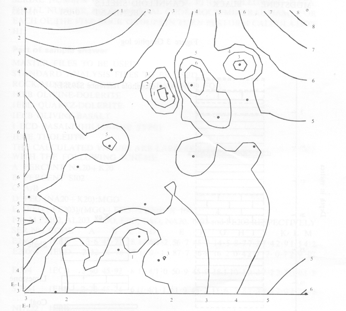
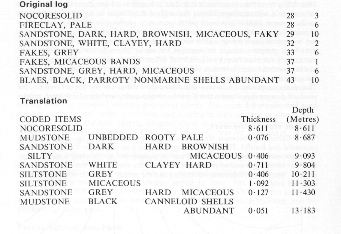
The core of a borehole is considered geologically as a sequence of recognisably-different rocks, each described by a thickness and several properties, such as 10 inches, sandstone, yellow and red striped, with abundant marine fossils. This basic information may be augmented by interpretative data such as the names of the fossils, and the stratigraphy assigned to the layer. The basic data is stored separately from the rest, so that changes in interpretation do not affect the original data. The stratigraphic data is held as a string of pairs of depths and four-or-five digit codes, the latter taken from a hierarchical table at the front of the bank tape, where also the English versions of the stratigraphic names are held. The beginning of the tape also houses the basic vocabulary - about 400 words - and a palaeontological vocabulary. The basic data file consists of pairs of depths and word strings, where the word string represents as many bits as there are words in the appropriate sections of the vocabulary. Bits set to one indicate the presence of corresponding properties. The exact composition of the bit-strings has varied somewhat since the original pilot project and is still under consideration. The first project used data for 33 boreholes in the Midland Valley of Scotland, input as a string of words from the basic vocabulary followed by a depth. Retrieved output included contour plots as an option useful for mapping coal seam depth or thickness (Fig. 1). All the routines for the first project were written in Atlas Basic Language, so that a complete rewrite is necessary for transferring the system to the 360/195. This opportunity has been taken to split the loading into two parts; the first part has several different forms to allow for several different kinds of input, varying from highly-coded to near-English, so that whatever system is convenient at the time can be used by the various geologists logging bores. Fig. 2 shows one scheme, used for translating from old Scottish mining terms to standard modern geological idiom. The output from the first part consists of the printer output as shown, and a string of data on tape or disc corresponding to this, in the form (depth, integers) where the integers refer to words in the vocabulary. This data string will be the same whatever form the input takes, so that all inputs converge to the same final form.
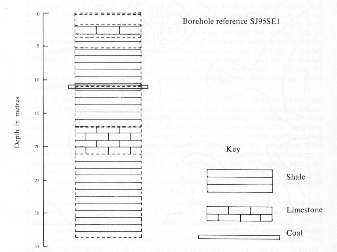
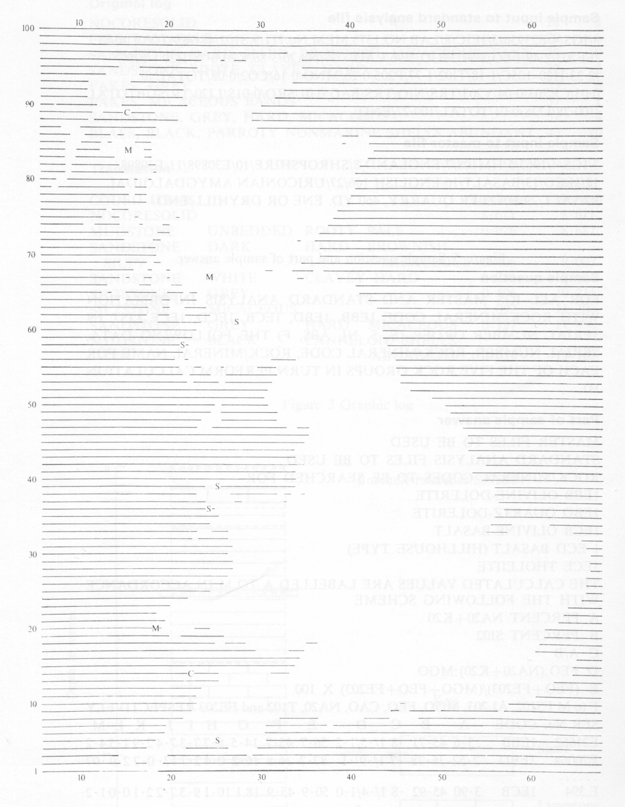
An option either during first-stage loading or after retrieval is the production of graphic logs, (Fig. 3), a pictorial representation of a borehole with different symbols to represent different rock types. This is a standard geological technique, and its computerisation represents an enormous saving in time. The programs for this were written by IGS staff themselves, for their 1130 which has a CIL plotter attached. A similar programme has been written for the SD4020 at Atlas so that logs may be produced at either place.
This bank is designed to take all the data about any rock specimen from the first rough notes as to its discovery to the last detailed analysis by a method not yet invented. The minimum entry for any rock consists of its specimen number (used as a cross-referencing index) and the name of the Institute holding it, and generally also details of where it was found and what kind of rock it is now thought to be. All the basic information is held on a Master file, a fixed-format array containing both numeric and textual information, any of which may be used for sorting data at retrieval time. Included in the Master file is a set of pointers to other types of file for this specimen, such as chemical analysis, optical properties, and a text file of further information which can be printed on retrieval but not used to sort on. As further information is acquired about the rock it can be added. New types of file may be introduced, and old ones edited or extended (although this latter facility is not implemented yet).
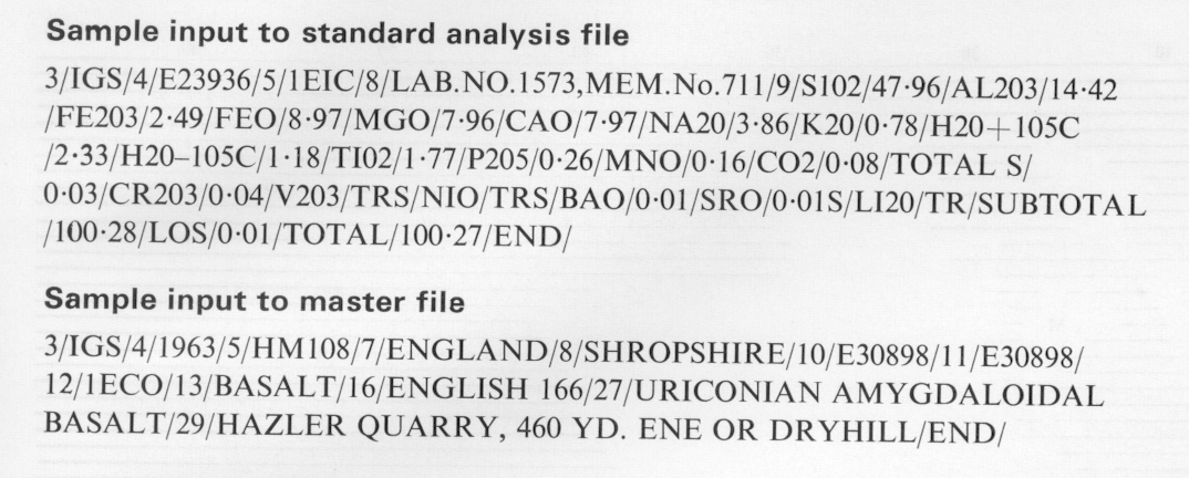
For all files other than the Master, information is held as a series of bit-patterns indicating the presence or absence of properties or items listed in a vocabulary unique to that file type, followed by a string of values corresponding to those items. For example, in the Standard Analysis files, the vocabulary, which is held at the beginning of the bank, consists of a list of element or oxide names, and the corresponding values are percentages of these found in the rock. Input to all files consists of pairs of labels and values, separated from each other and from neighbouring pairs by a slash, arranged in any order. A card at the beginning of each item states which file is to be used. The labels are then looked up in the vocabulary specific to that file and any new ones are added. Figs. 4 and 5 show typical input to the Master and Chemical Analysis files and a typical question and some of the answers.
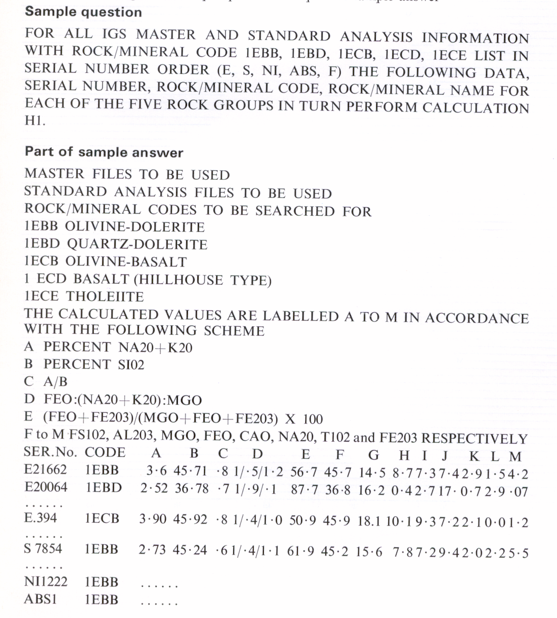
Information about 200 rocks forms the nucleus of the second pilot project on the bank, and retrieval has been achieved for a fairly general subset of these. Options on output include three-component triangular diagrams, scatter graphs with best-fit straight lines added if the standard deviation is low enough, and contour plotting. Locations of interest may be plotted on a simple lineprinter map using National Grid co-ordinates. (Fig. 6).
This differs from the other two in that data is stored as a by-product; the main aim is to produce a well catalogue. From the original data, input in highly coded form on cards, a paper tape is generated which goes to a phototypesetter. This produces a pleasing layout with several kinds of type, but is somewhat difficult to programme for because of the varying widths of spaces and letters, unlike the lineprinter. The data bank proper contains information for about 200 wells so far, and has been successfully retrieved from by a number of different kinds of inquiry. These programs, like the borehole ones, contain a substantial amount of Atlas Basic Language and are being considerably revised and rewritten in order that they can be run on the 360/195. The catalogue production is now done from the 1130 as the 360 has no facilities for producing paper tape - again therefore the preprocessing and data bank input proper have been separated.
The collaboration between the Institute and the Laboratory has certainly been successful and fruitful. This has encouraged the Institute to increase its computational resources considerably, both in staff and in equipment. At the same time its needs continue to increase and to require resources on the scale which the Laboratory can provide. Thus the collaboration continues and the present author is very happy to be involved in it.
