
GEC and CMS Version
PLUTO78 is the molecular drawing program from the Cambridge Crystallographic Data Centre in its 1978 form. It has been extensively modified at RAL for use on interactive systems, (CMS and the GEC computers connected to the SERC X25 network ), and on batch IBM central computers for high quality output to the FR80 microfilm recorder. A comprehensive HELP system is available to the interactive programs.
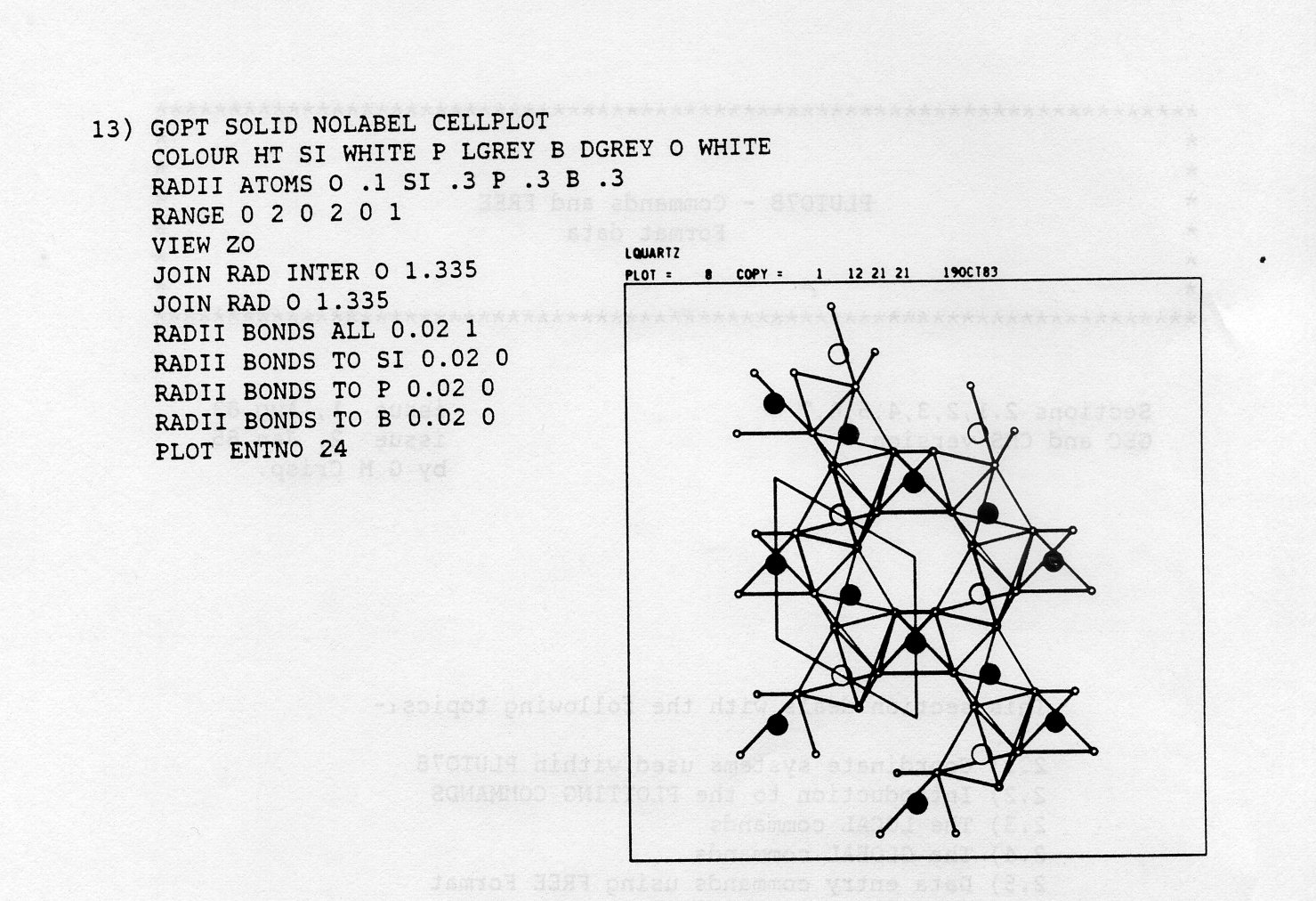
When working interactively the viewing position is altered by typing in simple commands at the terminal. The molecule is drawn in several formats, such as stick, ball + spoke, space filling, unit cell packing, half tone and colour. Colour is supported on both CMS (on Sigma 5660, 5680 terminals and Calcomp 81 desktop plotters), and the GEC's (on sigma 5660, 5680 terminals and Benson 1302, 1332 plotters).
The plotting commands can be submitted across the network to the batch version of PLUTO78 to produce output from the FR80 as high quality film, in black & white or colour 16/35 mm, black & white 105mm microfiche at 48 times reduction or hard copy paper. The output is posted back to your site. You may also obtain good quality stereo pairs on 35mm film which fit into the inexpensive Open University stereo viewer.
You can adjust the speed of plotting on the screen, to either take a quick, rough, look at your molecule or plot it more slowly and carefully. The latter method enables you to take a reasonable photograph from the screen, or to use one of the direct hard copy devices. The best of these does not give FR80 quality but you will have the results more quickly. On application to the Graphics section, a Dunn camera at RAL may be used to record plots directly from the screen of the colour GOC onto your 35mm film, which you take away for developing locally.
The commands are applied to the atomic coordinate data defining the molecule, which can be input from the terminal or from a file in either Cambridge database format or Free format. Free format enables you to enter coordinates quickly, for large numbers of atoms, to see the plot immediately and to save the data in a file for later use. These files are known as datasets.
Examples of the types of plot available follow. Details of the coordinate systems used by the programs, the commands, and an example of Free Format data are in section 2. Instructions for running PLUTO78 on CMS are in section 3.1, and on a GEC in section 3.2. Section 4 explains the Cambridge database format (also known as FDAT) used by PLUTO78. Section 5 contains various definitions, defaults and indexes.
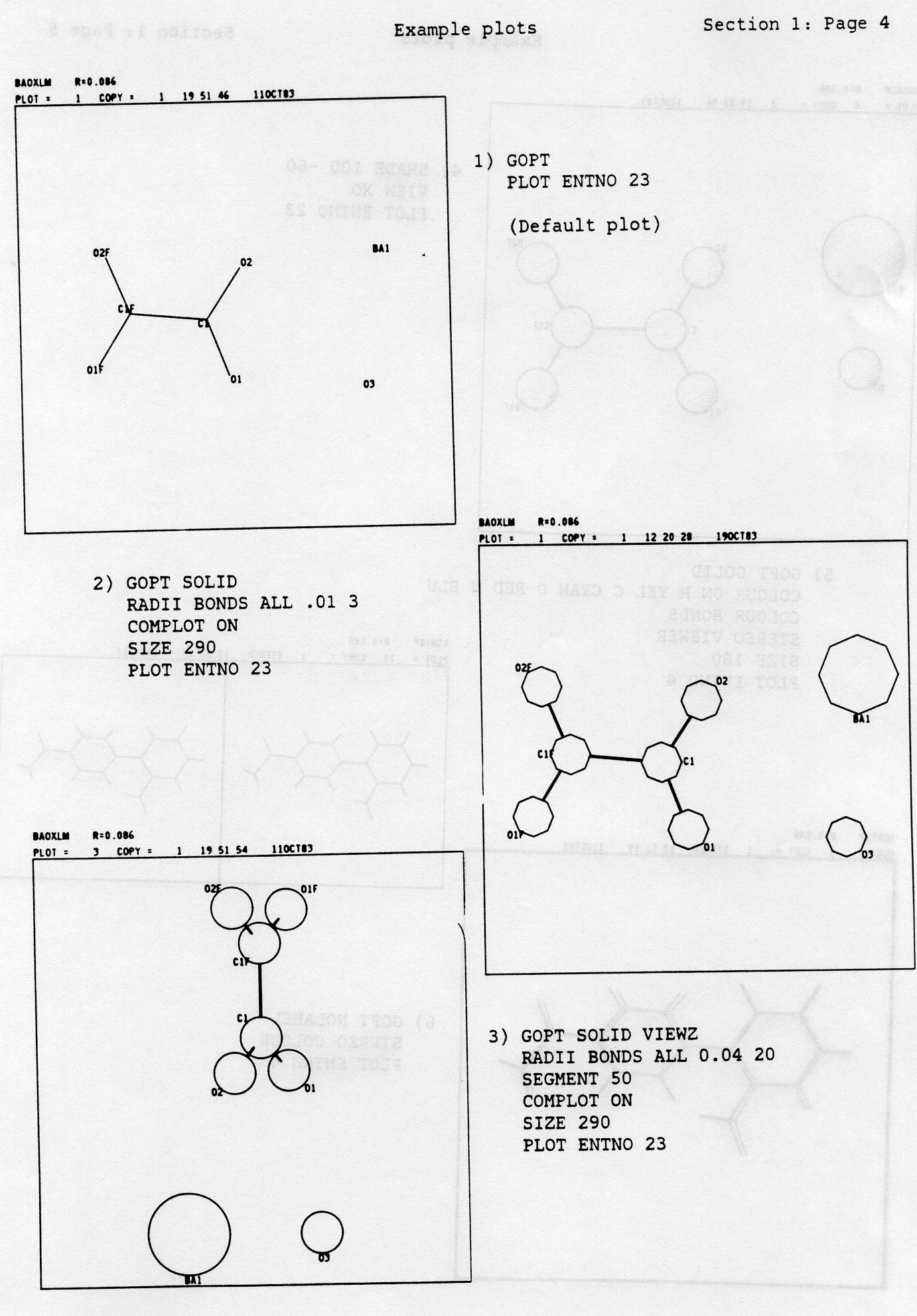
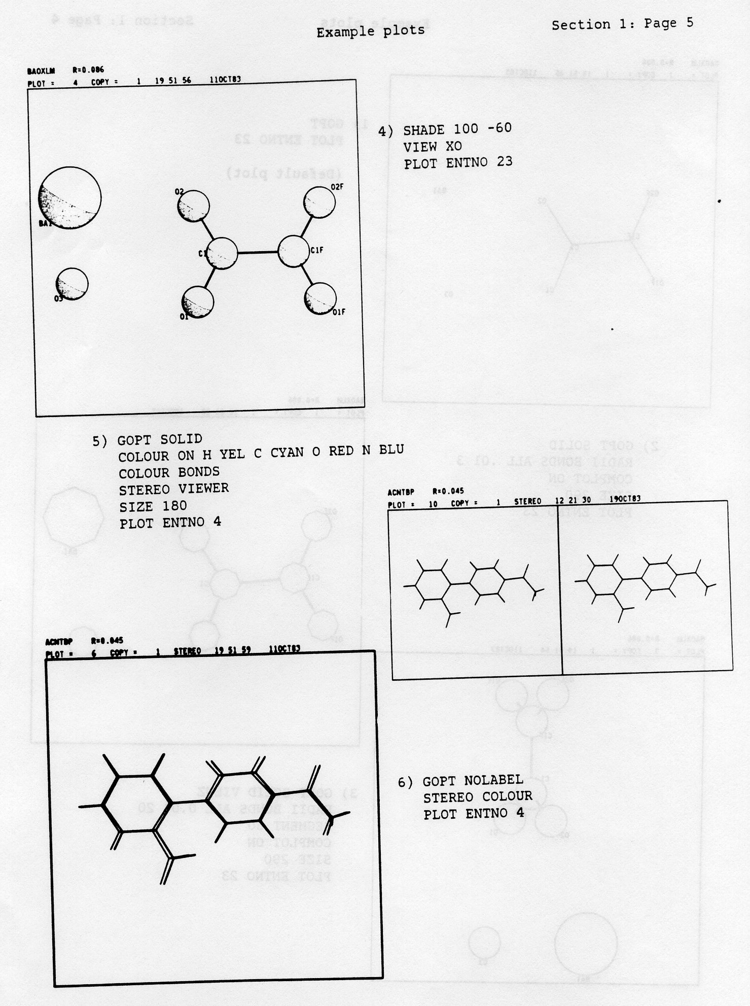
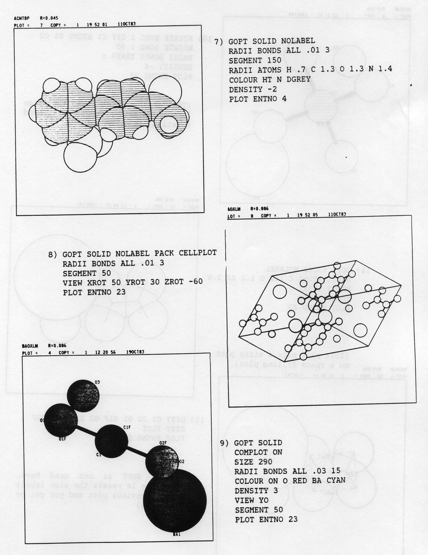
All the plots in this section are of two different molecules taken from the standard set of data available on both CMS and the GEC's. Each plot is given with the command set that produced it. Details of the commands are given in section 2, with a summary in section 5. A set of commands for a continuous demonstration are held in file PLDEMO COMMAND D on CMS (a private minidisk, see section 3.2.15), or .PLDEMCOM on GEC's (see section 3.2.15). In all the examples, references to COLOUR only apply exactly to a Sigma colour terminal. Other terminals will show either white or grey shades.
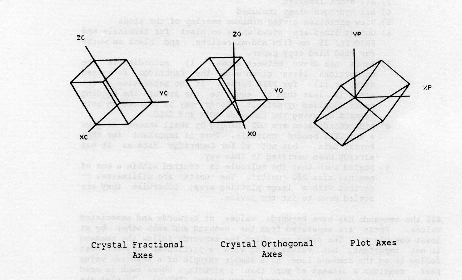
PLUTO78 uses three right handed cartesian coordinate systems in plotting a molecular or crystal structure (see figure below). Atomic coordinates are generally input in fractional units referred to the set of crystal axes XC, YC, ZC. These are transformed to an orthogonal set of axes internally, XO, YO, ZO, such that the atomic positions within the unit cell are measured in angstroms. Before a structure is plotted on the screen or an FR80 output device, the coordinates are transformed again to plot axes, XP, YP, ZP, which have units nominally in millimetres. However, on some output devices (for example, 35mm film) the units are scaled automatically for the user's convenience, to give the largest possible size of plot for that device. The XP, YP, ZP directions on the device are: XP horizontally from bottom left to bottom right, YP perpendicular to XP from bottom left to top left, and ZP normal to both and directly out of the plotting surface.
The plots produced by PLUTO78 are controlled by typing commands. These are grouped into three types, those which RESET default values of flags and variables, QUALIFY these values with new ones, and INITIATE plotting. There are two commands to reset (OPT and GOPT), many which use qualification and a single command to initiate the plot (PLOT). The simplest example has two commands:-
OPT
PLOT
Each command MUST start in column 1 and end before column 80. Commands may not be continued onto the next line. Some should only be given once, others can be repeated. The default plot is shown as Example 1 and consists of:-
All the commands may have keywords, values, or keywords and associated values. These are separated from the command and each other by at least one blank. The order in which the keywords follow the command is not important, but values going with a particular keyword must follow it on the command line. As a simple example of a keyword/ value pair, consider a dataset of more than 1 structure where each is read into the program with an associated entry number (ENTNO). To plot the xx'th one, use the command:-
PLOT ENTNO xx
The commands are further subdivided into categories LOCAL and GLOBAL. GLOBAL ones (mostly RAL additions) are obeyed for many plots, while LOCAL ones affect only a single plot, unless they are reset (by GOPT or OPT) before plotting starts. Consider the following examples:-
GOPT SOLID	    GOPT SOLID
SEGMENT 50	    SEGMENT 50
PLOT ENTNO 1    PLOT ENTNO 1
GOPT SOLID	    OPT SOLID
PLOT ENTNO 12	PLOT ENTNO 12
The SEGMENT command specifies how many straight line chords are to be drawn to complete the atom circle. In the left hand set, entry 1 is plotted with 50 segments, a GLOBAL reset done and then entry 12 plotted with the default of 8 segments. In the right hand set, entry 1 is plotted with 50 segments, a LOCAL reset done, and entry 12 plotted with 50 segments. Note that the SEGMENT is still in force.
Cambridge commands are indicated by a 'C' in the command name column, and additional RAL commands by 'R'. A summary of the Keywords associated with the RESET command OPT follows:-
OPT   COMMAND   KEYWORD         MEANING
00C)..OPT.......................Set up default options.
01R)............ANGLE...........Calculate bond angles and print them out.
02C)............CELLPLOT........Plot outline of unit cell.
03C)............DEBUG...........Invokes debugging facility.
04C)............NOHYD...........Omit all hydrogen atoms.
05C)............NOLABEL.........Suppress all atom labelling.
06R)............NOTITLE.........Suppresses output of title.
07C)............PACK............Plot packing diagram.
08R)............PFRED...........Print free format data on terminal when input is from disk.
09C)............SEPRES..........Treat each bonded residue by itself.
10C)............SOLID...........Plot ball + spoke model.
11C)............STEREO..........Plot side-by-side  stereo pair.
12C)............VIEWS...........View  down  shortest of XO,YO,ZO.
13C)............VIEWX...........View along XO.
14C)............VIEWY...........View along YO.
15C)............VIEWZ...........View along ZO.
VIEWX indicates that the view direction is along XO
VIEWY .......................................... YO
VIEWS .......................................... ZO
VIEWS .......................................... the shortest of XO, YO, ZO
If VIEWm (m = X, Y, Z or S) is absent the program will choose the view which gives the minimum overlap (see section 5.1 of the manual). These keywords may be overridden by the qualifier command VIEW.
QUALIFIER KEYWORDS MEANING
COMMANDS +VALUES
16C)..C...............TEXT......Comment record.
17C)..CALC............BOTH......Calculate 'non-standard' connectivity.
18C)..COLOUR........KEYWORDS....Specify colour of lines for plotting.
19R)..DCLEAR..........NONE......Erase current Free-format data-in-core and reset flags
and variables for next set of data.
20R)..DIRCOS........KEYWORDS....Specify a vector within the molecule and calculate
its direction cosines, or form a right-handed set of
axes, or calculate the crystal diamagnetic susceptibility.
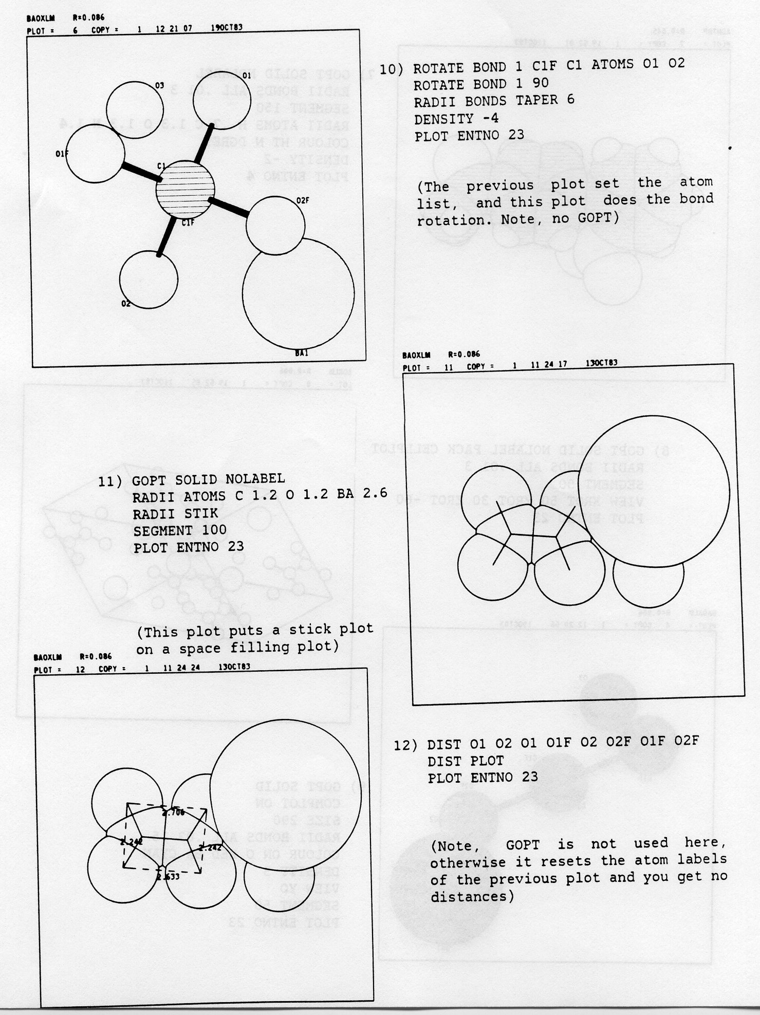
21R)..DIST............BOTH......Specify two atoms and print out the distance between them,
or define plotting of the distance on the device.
22C)..EXCL..........KEYWORDS....Exclude the specified elements.
23R)..FR80............NONE......Send current commands/ data to file.
24R)..HELP..........KEYWORDS....Invokes the help facility.
25C)..INCL..........KEYWORDS....Include the specified elements.
26C)..JOIN..........KEYWORDS....Specify connectivities.
27C)..LABEL.........KEYWORDS....Plot specified element labels only.
28C)..MATRIX.........VALUES.....Specify rotation matrix.
29C)..MOLE...........VALUES.....Specify molecules for packing.
30C),.PERSP..........VALUES.....Plot with perspective.
31C)..PLOT............BOTH......Initiate plotting.
32C)..PRINT...........NONE......Print out geometry + connectivity.
33C)..RADII...........BOTH......Specify radii of atoms, bond cylinders, or the inclusion of
a stick plot overlaid on a space filling plot.
34C)..RANGE..........VALUES.....Specify range of unit cell for packing.
35C)..SHADE..........VALUES.....Shade atom circles.
36C)..STEREO.........COLOUR.....Specify red/ green stereo pair.
37R)..STEREO.........VIEWER.....Specify Open University stereo pair.
38C)..STOP............NONE......Closes output files + stops program.
39C)..TITLE...........TEXT......Print specified title at top of plot.
40C)..VIEW............BOTH......Specify view direction.
CALC INTRA RAD CU 1.7 TOL 0.5
COLOUR keywordThe keyword can be RED or GREEN. It has no effect on non-colour devices. All the lines in the plot are drawn using the specified colour, on colour display devices.
EXCL EL1 EL2 EL3 etc...It excludes from the plot atoms corresponding to the specific atom types EL1, EL2, EL3 etc.,. For example:-
EXCL Hin a compound containing H, C, O, N leaves out the hydrogen from the plot.
HELP SOLID
INCL ELI EL2 EL3 ...As an example:-
INCL C O Nin a compound containing H, C, O, N leaves out the hydrogen from the plot.
LABEL MOLE EL1 EL2 ELS etc...The keyword MOLE causes the program to plot against the first atom of each symmetry generated molecule the number of the symmetry operator and the translation components which were used. If MOLE is absent no such annotation is produced. The keywords EL1, EL2 etc.,. are atom symbols and if they are present the program will label atoms only for those specified element types. The program tries to find a label position close to the relevant atom giving minimum overlap with other atoms, bonds and labels.
MATRIX r11 r12 r13 r21 r22 r23 r31 r32 r33r11...r33 are the components of the matrix which will replace the current rotation matrix. The program checks that the determinant of this new matrix is equal to + 1 within a tolerance +/- 0.0001.
OPT SOLID NOHYD
MATRIX -.9881 0.0270 0.1511 0.0864 0.9117 0.4017 -.1269 0.4100 -.9032
PLOT
MOLE s1 tx1 ty1 tz1 s2 tx2 ty2 tz2 etc...Each residue to be plotted is defined by two sorts of keywords, s = the serial number of the symmetry operator to be applied to the input residue, and tx, ty, tz = unit cell translations to be added to the symmetry operator. The first symmetry operator is always the identity, so if the input residue is to be plotted the command takes the form:-
MOLE 1 0 0 0 ....The values of s are available from previous calculations and appear on the terminal before plotting takes place. For a given plot more than one record may be needed to input the list of specified residues. Each continuation record starts with the command MOLE.
PERSP dThis causes the coordinates to be projected with perspective applied from a viewpoint d mm from the molecular model. Perspective can be incorporated into both mono- and stereo- views. If this command is absent the default action is to plot a mono- view with no perspective or a stereo- view with d = 600 mm.
PLOT TRACE a COPIES b ENTNO cThe keywords TRACE, COPIES and ENTNO are optional, but in the BATCH version care must be taken that ENTNO is specified when a single set of data is to be taken from a multiple set of data is run under a single command set. Failure to do this will result in all the sets of data being plotted until time or line limits are exceeded. TRACE causes the plot to be retraced a times, which can be useful when the plot has to be photographed. COPIES results in the production of b copies of the plot and was originally used for pen plotters. ENTNO specifies that only entry number c in the dataset is to be plotted. The 'c' associated with ENTNO can be either a number or the Cambridge format CODEN of 6 characters, e.g. 'PLOT ENTNO BAOXLM'. The CODEN is not applicable to FREE FORMAT. To get the next set of FREE FORMAT data you have to erase the current set of data using the DCLEAR command (see 19)).
RADII BONDS TO FE 0 1
RANGE xmin xmax ymin ymax zmin zmaxIn practice it is best to restrict the range to 1 cell translation on the axis closest to the view direction and to allow 2 cell translations along the other two axes. Thus for a z-axis projection the RANGE command takes the form:-
OPT NOHYD PACK VIEWZ
RANGE -.5 1.5 -.5 1.5 0 1
PLOT
SHADE a1 a2This causes the drawing of shade lines representing shadow from a light source whose position is defined by the two angles a1, a2. If a1 = a2 = 0 degrees then the light comes directly towards the viewer along the ZP axis so that the whole atom is shaded. The angles a1, a2 correspond to the rotation of the light about YP and ZP respectively. Convenient values of a1, a2 for approximate half-shading are 100, -60 degrees.
TITLE titlewhere title is any appropriate text (up to 74 characters long) to be printed at the top of the plot. All characters are converted to upper case.
*** Note: the '.' between words should not be typed, instead use a space.
Command                             Meaning
a)..VIEW.XO.........................View direction is along XO.
b)..VIEW.YO.........................View direction is along YO.
c)..VIEW.Z0.....................*...View direction is along ZO.
d)..VIEW.HOR.AT1.AT2.VER.AT3.AT4....Horizontal axis XP in direction AT1 to AT2. Vertical axis YP
                                    as near as possible to direction AT3 to AT4.
                                    For example, 'VIEW HOR Nl Cl VER Nl N3'.
e)..VIEW.LINE.AT1.AT2.HOR.AT3.AT4...View direction is along the line from AT1 to AT2. Horizontal
                                    axis XP in direction AT3 to AT4. For example,
                                    'VIEW LINE N1 C1 HOR N1 P4'.
f)..VIEW.BISECT.AT1,AT2.AT3.........View direction is along the bisector of the angle AT1-AT2-AT3
                                    towards AT2. For example, 'VIEW BISECT C1 N5 O4' .
g)..VIEW.PERP.AT1.AT2.AT3...........View direction is normal to the plane of AT1-AT2-AT3. For example,
                                    'VIEW PERP O1 CU1 O1A'.
h)..VIEW.PLANE.ATI.AT2.AT3.AT4.etc..View direction is along normal through AT1-AT2-AT3-AT4.. For example,
                                    'VIEW PLANE N1 C2 N3 C4 C5 C6'.
In addition to the special view directions, it is possible to specify any general direction by fixing the angles of rotation with respect to the plotting axes. The convention is:-
Clockwise rotation of the model when looking along the axis from its positive end towards the origin corresponds to a positive rotation angle. Rotations about XP, YP, ZP are indicated by:-
XROT a YROT b ZROT c
where the rotation about XP is a degrees, about YP is b degrees and about ZP is c degrees. For example:-
OPT SOLID NOHYD
VIEW PERP C1 C2 C3 ZROT -30 XROT 45
PLOT
The VIEW PERP command generates a view direction normal to the plane Cl, C2, C3, The corresponding rotation matrix is stored as the current matrix. The program next rotates the model by -30 degrees around ZP and then by 45 degrees around XP. The current matrix is modified to take account of these rotations and the new rotation matrix is stored as the current matrix. The final version of the current matrix is used to plot the model.
These commands remain in force over many plots unless reset by the GLOBAL options command GOPT (which has the same keywords as OPT), or changed by using the command to redefine keywords and values. In the summary below, 'C' following the command number denotes an original Cambridge command, 'R' an RAL extension.
COMMAND NAME       KEYWORDS      MEANING
                   +VALUES
00R)..GOPT........SAME.AS.OPT...Set up default options.
01R)..COLOUR........KEYWORDS....Specify atom/ colour pairs, or coloured bonds.
02R)..COMPLOT.......KEYWORDS....Commands are listed on the plot.
03R)..DEMO...........VALUES.....Set up a continuous demonstration with a variable
                                amount of time between plots.
04R)..DENSITY........VALUES.....Specify the spacing of lines which shade atoms,
05R)..INTENSITY......VALUES.....Set up scaled intensities for all colours on FR80.
06R)..INTHIT..........BOTH......Set up absolute intensities + hits of colours on FR80.
07R)..JOIN............BOTH......Allows atoms to be joined within specified distances,
                                groups of atom bonds to be coloured, and display
                                limits defined.
08R)..MANYUP.........VALUES.....Set up the FR80 hard copy many subdivisions,
09R)..MOVE............BOTH......Allows you to move molecules within the unit cell and
                                move the origin of the whole plot.
10R)..ROTATE..........BOTH......Specify bond rotation.
11R)..SEGMENT.........BOTH......Specify the number of segments in the atom circles.
12C)..SIZE............BOTH......Set up the size of the plot.
BLACK WHITE RED BLUE GREEN YELLOW CYAN MAGENT LGREY DGREY
 C     H     O   N    Cl    S      Br    P     O,N  Rest
Where possible, normal chemical convention is followed for atom colours, but the choice of the atoms is given according to the most frequently occuring elements in molecules.
BLA, W, R, BLU, G, Y, C, M, L, D
DEMO nwhere 'n' is an integer which determines the amount of time between plots. If no value of 'n' is given, a default of 100,000 is used. Values between 50,000 and 200,000 are useful, but note that the real time between plots depends on the type of computer, its load and your connection to it.
INTENSITY 0.7
INTHIT BLACK 200 1 RED 255 7
CYAN, YELLOW, GREEN, MAGENT, BLUE, RED, WHITEThe default may be changed by adding the colour name list to the default command JOIN ALL COLOUR. Thus to colour the first set of bonds red and the second blue, and leave the other sets, if they exist, as the defaults use:-
JOIN ALL COLOUR RED BLUEThe LIMIT keyword specifies a region within which atoms are joined and outside of which connections are ignored. The limits are taken along the XC,YC,ZC crystal axes and are defined in the same way as for the RANGE command (see section 2.3, 34C) ). For example, xcmin = -2 or 1.3 are both valid. This part of the JOIN command is distinct from the RANGE command, and has the advantage that once the RANGE of the crystal lattice has been defined the JOIN LIMITs can be repeatedly changed or RESET. The LIMIT DUMP allows inspection of the current LIMITs. Examples are.-
JOIN ALL O TO O 2.0 2.5
JOIN ALL RESET
JOIN LIMIT 0 1 0 2 0 .5
MANYUP I J
ROTATE BOND 4 C1 C2 ATOMS C3 C4 C5
ROTATE BOND 4 C1 C2 ATOMS H3 H4 H5 H6
SEGMENT 20
SEGMENT 50
There is an additional keyword 'FR80' which the interactive program ignores. It is used in the BATCH version to indicate that the SEGMENT command is to be acted on. By default all film and hard copy paper with multiple plots use SEGMENT 50 for ball + spoke and SEGMENT 150 for space filling plots. This is done to obtain an acceptable plot and to minimise the CPU time required to produce the output. The hard copy single paper output defaults to SEGMENT OFF to give the best quality. By using 'FR80' on the SEGMENT the effects of the BATCH defaults are overridden. If, for example, an interactive plot of a molecule is made in ball + spoke with 20 segments, then:-
SEGMENT 20gives a batch hard copy multiple-type plot with 50 segments, but the use of 'FR80':-
SEGMENT 20 FR80gives a multiple-type plot with 20 segments.
SIZE s1 CHAR s2 SCALE s3 XMIN x1 XMAX x2SIZE defines the size, nominally in mm units, of the square frame enclosing the plot. Note that the mapping onto the device does not always give units as millimetres. It has the following default values of s1:-
125 units, for a side by side stereo pair.
220 units, for a single view.
CHAR defines the character height for labels and the title and is principally of use on the FR80. On terminals, hardware generated characters are used and these are unaffected by CHAR. The default is s2 = 3, which produces characters about 2.5 mm in height. SCALE defines the scale of the plot in mm. per angstrom. If SCALE is specified with value s3, then s1 is ignored and no enclosing frame is plotted. If the scaled plot is too large for the display area, then the excess portions are lost. XMIN and XMAX define the limits, in angstroms in the internal coordinate system, of the coordinates to be plotted, which is useful when these values of the fragment are known with respect to defined molecular axes and origin. In this case no relative scaling occurs. Some examples of the SIZE command are:-
SIZE 250
SIZE 250 SCALE 10
SIZE 250 CHAR 5 XMIN -5.0 XMAX 5.0
Data can be typed in from the terminal or read in from a disk dataset. In both cases, if the first character on the first data line is an #, Cambridge database format is assumed. If it is not an #, FREE Format is assumed. When input comes from the terminal, the program will first prompt you to type in the 3 characters, 'VDU', in order to set flags correctly. Then a FREE FORMAT dataset can be entered. It consists of the following records:-
*** Note : records 1,4,5) are mandatory.
CELL 12.90 3.91 28.54 90 90 90
CELL 12.901 3.952 28.543 99.12 121.34 102.6
SYMM X,Y,Z * l/2-X,l/2+Y,Z * ...
SYMH X,Y,Z * 0.5-X,0.33333+Y,Z * ...
xp = R11.X + R12.Y + R13.Z + Tl
yp - R21.X + R22.Y + R23.Z + T2
zp = R31.X + R32.Y + R33.Z + T3
The terms Rij and Ti are the elements of the rotation matrix R and the translation vector T connecting the symmetry points. Note that only one operator can be present on this type of record and that if SYMM records are absent, the default setting of the program is one GEP of X, Y, Z. An example of this type of record is as follows:-
SYMM -1 0 0 0.5 0 1 0 0.0 0 0 -1 0.5This represents the GEP 1/2-X, Y, 1/2-Z.
Nl
C12
BR3
If an atom is symmetry related to a member of the basic set then another one or two letters are added to the label to distinguish between atoms of different symmetry. Each letter added identifies the number of the symmetry operation used to generate the atom. For example, letter A goes with the first operation, B with the second and so on. Examples are:-
C12A
BR3F
N1AB
The record also contains the fractional atomic coordinates x/a, y/b, z/c referred to unit cell axes in the coordinate system XC,YC,ZC. These three values must be separated from the atom label and from each other by at least one blank character. An example of this record is as follows:-
C1 0.01 -0.02 0.03
This example is of the first plot ( 1.2) of entry number 23 (BAOXLM) in the test dataset of structures. See >section 2.5 for a description of the format of each record. The TITLE, atomic coordinates and END records are mandatory, and there must be at least 3 sets of atomic coordinates to define a plane.
TITLE BAOXLM FREE FORMAT DATA
CELL 10.10 7.96 6.83 90 121.96 90
SYMM X,Y,Z * X+1/2,Y+1/2,Z * -X,Y,-Z * -X+l/2,Y+l/2,-Z
BA1 0.2175 0.0 0.3153
C1 0.3615 0.403 0.2405
O1 0.4133 0.3346 0.1305
O2 0.3102 0.33 0.3516
O3 0.4712 0.0 0.2439
C1F 0.3615 0.5970 0.2405
O1F 0.4133 0.6654 0.1305
O2F 0.3102 0.67 0.3516
END
This format can be typed in interactively from the terminal and then plotted immediately by PLUTO78. If the data is to be stored, the command FR80 can be used AFTER the first plot. However, it is probably easier to prepare the data using the editor, and then plot it as a file of data read in from disk.
A PLUTO78 MACRO command is defined as a set of commands preceded by, and terminated by special records. The start of the MACRO command is indicated by the characters '* MACNAM', where MACNAM is any set of up to 6 characters. The end of the MACRO is indicated by '*END'. Between these delimiters, you may define any collection of valid PLUTO78 commands. The MACRO'S are held in a file and MUST be defined before the program is run. On CMS the file is called 'PLMACRO COMMAND' and if you haven't made such a file on your minidisk, the default on the PLUTO78 disk will be used. On the GEC's the file is called '.MACROCOM'. The file may contain more than one MACRO command and each is called by its name. For example, if you want to define a MACRO which sets up coloured bonds add the following to your MACRO file:-
* COLBND
COLOUR ON C CYAN O RED H YELLOW N MAGENT
COLOUR BONDS
*END
At any point during the running of the program you can type in reply to the 'COMMAND?' prompt:-
* COLBND
remembering to start in column one. This command input will result in the MACRO file being searched to find '* COLBND'. If is is found, the commands up to '*END' will be obeyed. If it is not found, the program will output the lines:-
*** EOF ON MACRO COMMAND FILE ***
*WARNING* UNRECOGNISED CARD
to the terminal and then the 'COMMAND?' prompt will be given.
*** Note: This MACRO file is NOT the same as the file used when you want to run your command sets from disk, instead of from the terminal. If you specify the MACRO file when you mean the file of command sets, the program will produce unpredictable results. A typical file of command sets is 'PLDEMO COMMAND' on CMS, and '.PLDEMCOM' on GEC's.
This document briefly describes how to use PLUTO78, the molecular drawing program from Cambridge in its 1978 version. It runs interactively under CMS and also on the RAL BATCH system. Under CMS, PLUTO78 lets you look at molecular data and decide which set of drawing instructions (called command sets) give useful plots. These instructions and data can then be sent to the batch system to produce high quality microfiche, 16/35 mm black + white or colour film, and hard copy paper output on the FR80 microfilm recorder.
You need a valid identifier and account for CMS in order to use PLUTO78. If you want to use the FR80, you also need a valid identifier and account on the BATCH system. The document entitled 'An introduction to CMS on the RAL coupled system' (RL-80-008, second edition) gives all the necessary information for interactive use, and a copy of it is given to new users. When you run PLUTO78 under CMS you need a virtual machine (vm) of 1 megabyte, but your initial vm size will probably be 512kb. To change this temporarily during the session you must type in the command:-
DEFINE STORAGE 1M
and follow this by typing:-
IPL CMS
to recreate your vm. Then type return. To change your vm size permanently you must type in the command:-
DIRM STORAGE 1M
and then logout and logon again. To check your vm size, type the command:-
Q STOR
To run the program you must have access to PLUTO78 EXEC, PLUTO78 MODULE and PLUTO78 HELPCMS.
In order to use PLUTO78 EXEC and HELPCMS you must access the U-disk at the start of your session. To do this type the command:-
UDISK (MODE U
The U-disk is now accessed as your U minidisk.
You must now type in the command:-
PLULINK
to link to the disk containing PLUTO78 MODULE. By default this disk will be linked as your D-disk. There are two files on the U -disk called PLULINK EXEC and PLULINK HELPCMS that you can access if you want more information.
If you want to run the program using the test option or with permanently stored data, see sections 3.1.14,15.
*** Note : running on a graphics device will probably use a lot of your accounting units. If you just want to see what sort of output PLUTO78 can produce on a tektronix 4010, type in 'GVIEW PLUTO78 GRAPHICS', or see sections 3.1.3), part f) , 3.1.11) for more information.
PLUTO78 consists of six parts :-
a) PLUTO78 MODULE ......  this is the non-  relocatable load MODULE,
                          stored on the PLUTO78 minidisk  (see section
                          3.1.2 for linking information).
b) PLUTO78 EXEC ........  this EXEC is stored on the CMS U- disk (see
                          section 3.1.2) and runs the MODULE when you type in the command:-
                            PLUTO78
c) PLUTO78 HELPCMS .....  this is the HELPFILE which is stored on the
                          U- disk. (see section 2). It briefly describes
                          what PLUTO78 is and contains the various HELP facilities
                          called by the program. It will run under the CMS HELP
                          system when you type in the command:-
                            HELP PLUTO78
d) PLSECT31 SCRIPT .....  is this section of the user manual.  This is
                          available on the PLUTO78 minidisk.
e) PLSECT2 SCRIPT ......  this document contains all the commands and
                          specifications for free format data entry.
                           It is on the PLUTO78 minidisk.
f) PLUTO78 GRAPHICS ....  this  is  a set of  demonstration plots,
                          suitable for viewing on a tektronix 4010, using the
                          CMS GVIEW command (see section 3.1.11). It can be
                          viewed from the PLUTO78 minidisk.
A copy of the 1978 Cambridge manual is available for reference in the Atlas centre, RAL. Ask either Mrs K M Crennell or Dr G M Crisp.
To produce graphical output you need a tektronix 4010 or a sigma 5660/70. If you want to use either the test option (see section 3.1.11) or submit a job to BATCH (see section 3.1.14), then you need only an ASCII terminal or a teletype. Available line speeds are:-
300, 1200, 2400,4800 Baud
if you access CMS from SERCNET.
The EXEC runs the MODULE and allows you to interrogate
You can list the HELP file - PLUTO78 HELPCMS - from the terminal by typing in the command:-
HELP PLUTO7B
The EXEC lists the HELP file when you type in:-
HELP
in response to certain EXEC prompts. The PLUTO78 program uses the HELP file slightly differently, in that you can look at particular sections of the file when you type in:-
HELP XXX
in response to either of the program prompts:-
COMMAND?
DATA?
XXX indicates any valid name in the HELP file and if you want to find out what HELP is available, just type in:-
HELP
You can type data interactively from the terminal if you have specified the terminal in response to the appropriate EXEC prompt. If you specify an existing CMS or OS- disk, then the program will take data from this source. The program asks you whether the data file consists of a single set or many sets of molecular data. If many sets of data are expected, the program asks you whether a single set or many sets of commands will be used. A single set of data has only many sets of commands, but many sets of data can have either:-
a) a single command set, so that all the molecular data is processed in the same way. You can find this useful if you want to look through all your data without re-typing the command sets.
b) many sets of commands, so that each set of molecular data can have any number of command sets by which it is processed. You can use this to find out which command set bests suits the current set of molecular data, before storing the commands in a file for use on the FR80 (see section 3.1.12).
You can type commands interactively from the terminal, if this has been specified in the EXEC, or you can read the commands in from a file which already exists on CMS or OS- disks. Section 1.2 of this manual gives several PLUTO78 example plots, including their sets of commands. These commands are stored in PLDEMO COMMAND on the PLUTO78 disk.
A simple test option exists in the CMS version of PLUTO78 which bypasses the graphics routines. It can be used when specified in response to the appropriate prompt from the program. This option is an aid to debugging data, in addition to the 'OPT' keyword qualifier 'DEBUG', and provides one line output when entering routines associated with data input and handling. This allows you to monitor the progress of the progam. A typical one line output is:-
*** ENTERING INTERP. 1ST CALL ***
*** Note This option is in addition to the DEBUG command which outputs variables and arrays.
You can store graphical output in a file for viewing later if you specify a filename when the EXEC prompts you to initialise the graphics device. The filename must only have up to 5 alphanumeric characters, because the system appends a three digit version number to make the file unique. You specify this name after the device speed, and you need all the parameters specified. For example if you type in the command:-
T4010 4800 TKOUT
when prompted, the system stores your graphical output in a file -TKOUT001 - in the common GRAPHICS filestore. You can look at this file, on a tektronix, by typing in the command:-
GVIEW TKOUT
The system erases the file after 15 days, but you can save it by copying it to your CMS minidisk by typing in the command:-
GCOPY TKOUT AS MYTEK
This gives you a copy of - TKOUT - known as - MYTEK GRAPHICS A - on your minidisk.
To view this file type in the command:-
GVIEW MYTEK GRAPHICS
For more information type in the CMS commands:-
HELP GVIEW
HELP GCOPY
A set of example plots, suitable for display on a tekronix 4010 and generated from commands similar to those in 'PLDEMO COMMAND D', are held in 'PLUTO78 GRAPHICS D' on the PLUTO78 D-disk. The command to type in to view these is:-
GVIEW PLUTO78 GRAPHICS D
PLUTO78 allows you to use the FR80 by submitting a batch job from CMS. This job file contains JCL, and your command sets and molecular data (if necessary) are taken from CMS disk files. You create these files when prompted from the EXEC, but in case you forget to do this the system creates default files in your filestore with names such as:-
FILE FT10F001
where the filename is - FILE - and the filetype indicates that output comes from FORTRAN stream 10 in the program. Stream 10 outputs commands and stream 11 outputs data. When running the program you send your current command (and terminal data) set to the files by typing in the CMS command:-
FR80
every time you want to save the current command set. Note that if you are using FREE format data, it can only be saved immediately after the current set has been closed and the first plot made.
You submit jobs to the BATCH system by typing either of the commands:-
PLANT FRCOM JOB A
PLANT FRCOMDAT JOB A
The use of PLANT rather than XPLANT is to maintain compatibility with the use of PLUTO78 on the GEC's. The files - FRCOM, FRCOMDAT - both contain the same JCL but the first needs to include only command sets, whereas the second needs both command and data sets. A copy of each of these files is stored on CMC's D disk (see section 3.1.2).
The system EXEC - PLANT - prompts you for the following input:-
JOBNAME   - (e.g. MYPLUTO1)
ACCOUNT   - (MYACC)
ID        - (MYID)
CAMERA    - (MFCH (microfiche) is the default and the user will have to
             supply this explicitly in response to 'USER ARGUMENTS>'
             e.g. CAMERA=HCM (hard copy many))
DATANAME   - (USER.ID.MEMBER (OS) or FR80 DATA (CMS))
DISKNAME   - (RHEL03)
COMMANDS   - (FR80COM DATA)
M/S_DAT?   - (M, for a multiple set of data, S, for a single set.)
M/S_COM?   - (M, for a mutliple set of commands, S, for a single set.)
For more information on cameras available, type in the CMS command:-
HELP GRAPHICS
FR80 output is routed by Operations to the user with identifier MYID, in this example.
This sample session does not try to present a complete picture of the way in which you can use PLUTO78, but rather to illustrate the salient features. In the following text your input is indicated by the characters:-
->
which are not part of the CMS prompt. Any input such as <XXX> means that you type XXX, <CR> means type return. After you log on and CMS is ready to receive your input, the short ready message (R;) and the prompt (.) are displayed. If you access CMS via the network, then the prompt may be absent.
R;
-> PLUTO78
DEVICE TYPE AND SPEED?, OR <CR>
-> <CR>
ALLOWED TYPES ARE :- TEKT T4010, T4014, SIGMA S5600, S5660, S5674, S5671
                     S5470, CALCOMP CALC81, CALC81R, HELP, Q, END
EXAMPLES :-
1) T4010 4800 ... ... (TEKT. 4010 AT 4800 BAUD)
2) TERM ... ... ..... (DEFINES TELETYPE OR RETAINS CURRENT DEVICE)
3) HELP ... ... ..... (INVOKES CMS HELP FACILITY)
4) Q ... ... ... .... (QUERIES GRAPHICS DEVICE)
5) END ... ... ...... (ENDS EXEC)
6) T4010 4800 TKOUT . (GRAPHICS OUTPUT SENT TO FILE TKOUT001)
ALLOWED SPEEDS ARE :- 300, 1200, 4800
DEVICE TYPE AND SPEED?, OR <CR>
-> TERM
PLUTO DATA FILENAME?, OR <HELP>
-> HELP
FILENAMES ARE DEFINED AS :- INPUT NAME1 NAME2 NAMES NAME4 NAME5
WHERE :- INPUT IS ONE OF, TERM, CMS, OS, END, HELP.
WHERE :- NAME1, ..NAME5 ARE PARTS OF FILENAME ON CMS, OS-DISKS.
EXAMPLES :-
1) TERM ... ... ... . (INPUT FROM TERMINAL)
2) CMS MYFILE FTYPE . (CMS FILE WITH NAME - MYFILE, TYPE - FTYPE)
3) OS JAN IDFRED .... (OS FILE JAN . IDFRED ON FREEDISK. ... ... ... ... ... LINK TO DISK LATER)
4) END ... ... ... .. (ENDS EXEC FOR PLUTO DATA + COMMANDS,
  ... ... ... ... ... BUT BYPASSES FR80 OUTPUT FILES)
5) HELP ... ... ... . (INVOKES THIS PART OF EXEC)
PLUTO DATA FILENAME?, OR <HELP>
-> CMS PLUTO78 DATA
PLUTO COMMAND FILENAME?, OR <HELP>
-> TERM
FR80 COMMAND FILENAME?, OR <HELP>
-> CMS FR80COM DATA
FR80 DATA FILENAME?, OR <HELP>
-> END
FILEDEF 8 DISK PLUTO78 DATA *
FILEDEF 1 T
FILEDEF 4 DISK FR80COM DATA *
FILEDEF 2 T
FILEDEF 9 T
FILEDEF 6 T
FILEDEF 3 DISK PLUTO78 HELPCMS *
FILEDEF 10 DISK XY20UT DATA *
FILEDEF 11 DISK ANGOUT DATA *
PLUTO78
ENTER DEVICE TYPE ONE OF TEST,4010,4014,5600,5660,5674,5671,5470,CALC8l, CALC81R
-> TEST
-** BYPASSING CRTPLT + OPTION. 1ST CALL ***
SINGLE OR MULTIPLE DATASETS ? ENTER <S/M>
-> M
DATASETS TO BE RUN UNDER SINGLE/ MULTIPLE COMMAND INPUT ? ENTER <S/M>
-> M
-** ENTERING INTERP. 1ST CALL ***
-** FOR HELP, ENTER <HELP> ***
COMMAND?
-> HELP
PLUTO HELP FACILITIES ARE AS FOLLOWS:-
COMMANDS - LISTS AVAILABLE COMMANDS  (ABBREVIATION COM)
NEWS     - CURRENT NEWS              (ABR. NEW)
WHOSWHO  - WHO TO CONTACT            (ABR. WHO)
DISKS -    USE OF CMS/ OS- DISKS     (ABR. DIS)
DATA -     FREE FORMAT DATA ENTRY    (ABR. DAT)
TIME -     BATCH/ FR80 OUTPUT TIMES  (ABR. TIM)
CAMERA -   FR80 CAMERA TYPES         (ABR. CAM)
OUTPUT -   FR80 OUTPUT TIPS          (ABR. OUT)
BUGS -     CURRENT KNOWN BUGS        (ABR. BUG)
FOR MORE INFORMATION ABOUT THESE FACILITIES ENTER 'HELP XXX'
IN RESPONSE TO 'COMMAND?' OR 'DATA?', WHERE XXX IS THE REQUIRED
FACILITY.
FOR USERS RUNNING PLUTO78 FOR THE FIRST TIME ENTER 'HELP START'
COMMAND?
-> GOPT NOLABEL SOLID
CONTROL CARD...GOPT NOLABEL SOLID
COMMAND?
-> PLOT ENTNO 1
CONTROL CARD...PLOT ENTNO 1
*** ENTERING READ1. 1ST CALL ***
READING DATA. IF ENTRY FROM TERMINAL ENTER <VDU>
NOW READING FDAT ENTRIES FROM UNIT 1
ENTNO=   1  ACNTBP   SPG=P21/C Z=  4 ATOMS= 29 INTF=3 AS=1 R-FACTOR(MIN,
MAX) = 0.045 0.045
*** ENTERING PLANE. 1ST CALL ***
*** ENTERING MINOV. 1ST CALL ***
RESIDUE  0 MIN. OVERLAP VIEW MATRIX 0.28176-0.95849-0.04377/ 0.95598 0.27654
0.09813/ -0.08195-0.06949 0.99421
GENERATING MOLECULES WITH OPERATOR 1 0. 0. 0.
TOTAL NUMBER OF ATOMS   29
VIEW ROTATION MATRIX   0.28176-0.95849-0.04377/ 0.95598 0.27654 0.09813/
-0.08195-0.06949 0.99421
SIZE OF PLOTTING AREA =   12.49 ANGSTROMS = 220.00 MM. SCALE FACTOR =
14.0942 MM/A
*** ENTERING BELLA. 1ST CALL ***
*** COMPLETED DRAWING NO.  1 - COPY NO.  1 - TRACE NO.  1
You may run PLUTO78 with a permanently stored dataset, called USER.NW.PLUTODAT which contains 180+ compounds, on OS- disk RHEL03, or a smaller set of 24 compounds on CMS disk in PLUTO78 DATA on the PLUTO78 disk. Find a tektronix 4010 or a sigma 5660/70, switch on and log onto CMS. Before running the program check your virtual machine size and make sure that you access both the U-disk and then the PLUTO78 disk (see section 3.1.2). The example which follows uses a small molecule containing carbon, oxygen and barium and has an entity number (ENTNO) of 23 in the dataset. A demonstration command set is stored in PLDEMO COMMAND on the PLUTO78 minidisk. Only the EXEC/ program output which prompts you for input is given below. Your input begins following the characters:-
->
which are only used to indicate the lines you type in, but are not part of that input. When CMS is ready for input you type:-
-> PLUTO78
DEVICE TYPE AND SPEED?, OR <CR>
-> T4010 4800
PLUTO DATA FILENAME?, OR <HELP>
-> OS USER NW PLUTODAT (or CMS PLUTO78 DATA *)
PLUTO COMMAND FILENAME?, OR <HELP>
-> TERM     (or CMS PLDEMO COMMAND * for the demo command set
            when PLUTO78 DATA is specified above)
FR80 COMMAND FILENAME?, OR <HELP>
-> END
FR80 DATA FILENAME?, OR <HELP>
-> END
LINK/ DETACH ANOTHER OS- DISK?, OR <HELP>
-> LINK RHEL03 K
DASD 120 LINKED R/O ; R/W BY FEM
*** RHEL03 ACCESSED , MODE K ***
LINK/ DETACH ANOTHER OS- DISK?, OR <HELP>
-> NO
FILEDEF 8 DISK USER NW PLUTODAT *
FILEDEF 1 T
FILEDEF 2 T
FILEDEF 9 T
FILEDEF 6 T
FILEDEF 3 DISK PLUTO78 HELPCMS *
FILEDEF 10 DISK XYZOUT DATA *
FILEDEF 11 DISK ANGOUT DATA *
ENTER DEVICE TYPE ONE OF TEST,4010,4014,5600,5660,5674,5671,5470,CALC81,
                         CALC81R
-> 4010
The terminal screen clears at this point and the bell sounds. To
continue, type return.
SINGLE OR MULTIPLE DATASETS ? ENTER <S/M>
-> M
DATASETS TO BE RUN UNDER SINGLE/ MULTIPLE COMMAND INPUT ? ENTER <S/M>
-> M
*** FOR HELP, ENTER <HELP> ***
COMMAND?
-> GOPT
CONTROL CARD...GOPT
COMMAND?
-> PLOT ENTNO 23
CONTROL CARD...PLOT ENTNO 23
*** Note : spaces in command lines are important.
Data about the molecule is displayed on the terminal, and when this stops a prompt appears and the bell sounds. The prompt is displayed at the top left hand corner of the tektronix screen and as normal text on the lowest line of the sigma alpha screen. The prompt is:-
>>> TYPE RETURN TO CLEAR SCREEN + NEXT PLOT
When you have looked at this data and wish to continue, type return.
The program plots the molecule and when this is done, a new prompt appears at the top of the screen and the bell sounds again. This prompt is:-
>>> TYPE RETURN FOR NEXT COMMANDS
When you have finished with this plot, type return to continue and you will be asked for another command. To stop the program, type in:-
STOP
The first prompt appears and the bell sounds, and when you type return you will be back in CMS.
*** Note : on some terminals which emulate a tektronix 4010 the bell may not sound when the prompt is given.
This document briefly describes how to use PLUTO78, the molecular drawing program from Cambridge in its 1978 version. It runs interactively on the ICF GEC's under OS4000 and also on the RAL batch system. On the GEC's, PLUTO78 lets you look at molecular data and decide which set of drawing instructions (called command sets) give useful plots. These instructions and data can be sent to the BATCH system to produce high quality microfiche, 16/ 35 mm black + white or colour film, and hard copy output on the FR80 microfilm recorder.
You need a valid identifier and account on the GEC, and also on RAL BATCH for FR80 output, in order to use PLUTO78. The document entitled 'An Introduction to OS4000' gives all the necessary information for using the GEC's, and a copy of it can be obtained from your local ICF GEC manager. You can use PLUTO78 interactively on a demonstration account which is set up at QMC (on ZMGA) under the ID/PASSWORD of NTIN22/PHENAZ. The maximum time and CPU available are 30 minutes and 100 IEU's. See sections 3.2.14, 3.2.15 for sample sessions.
On the ICF GEC's PLUTO78 consists of seven parts:-
a) .BPLUTO78 ........... this is the compiled + linked binary program.
b) .MPLUTO78 ........... this is the MACRO file which runs the program.
c) .PLUHELP ............ this is the GEC version of the HELPFILE.
d) .PLCOMOUT ........... this is an empty file which receives command
                         sets when the command 'FR80' is used.
e) .PLDATOUT ........... this is an empty file which receives any FREE
                         FORMAT data when the command 'FR80' is used
                         for the first time on the current set of data.
f) .PLXYZOUT ........... this is an empty file which receives bond
                         data when the command 'ROTATE SAVE' is used.
g) .PLANGOUT............ This is an empty file which receives angle
                         calculations when 'ANGLE' is used in the OPT
                         command.
A copy of the 1978 Cambridge manual is available for reference in the Atlas centre, RAL. Ask either Mrs K M Crennell or Dr G M Crisp.
To produce graphical output you need a tektronix 4010/14 or a sigma 5600/60/74. If you want to submit a job to RAL BATCH (see section 14), then you only need a vdu (without graphics) or a teletype. Available line speeds are:-
300, 600, 1200, 2400, 4800 Baud
You need to use the local convention for connecting to a node of the SERC X25 network. You can then call the GEC at QMC by typing in '!!ZMGA'.
The MACRO runs the BINARY file and allows you to interrogate :-
You can use the HELP file, .PLUHELP, from within the program when prompted by the output:-
'COMMANDS?'
'DATA?'
You type in either of the replies:-
HELP
HELP XXX
where the first form gives information on what help is available, and the second allows you to look at particular parts of the file. The XXX is the name of the part of the file which is of interest, for example COMMANDS, and names can be shortened to a minimum of 3 or 4 unique characters. You can also VIEW the HELP file from the terminal by using the GEC 'VIEW' command. This allows you to look through the file in pages of 23 lines, both forward and back, and to search for strings. Use 'HELP COMMAND VIEW' for more information.
You can type in data interactively from the terminal, if you have specified the terminal in response to the appropriate MACRO prompt. If you specify a disk file which already exists, then the program will take data from this source. The program asks you whether the data file consists of a single set or many sets of molecular data. If many sets of data are expected, the program asks you whether a single set or many sets of commands will be used. A single set of data has only many sets of commands, but many sets of data can have either:-
You can type commands interactively from the terminal, if this has been specified in the MACRO, or you can read the commands in from a file which already exists on disk. For more information on the commands available, see sections 2 and 5.5, 5.6 of this manual. Some 12 sets are given as examples in section 1.2.
A simple test option exists in the GEC version of the program, which bypasses the graphics routines. It can only be used when specifying the device, 'TEST', when prompted by the program. This option is an aid to debugging data, in addition to the 'OPT' keyword 'DEBUG', and provides one line output when entering routines associated with data input and handling, allowing you to monitor the progress of the program. A typical one line output is:-
*** ENTERING INTERP. 1ST CALL ***
At present graphical output from PLUTO78 can only be displayed directly onto the screen. There is no facility to divert this output to a disk file, at the MACRO level.
PLUTO78 only allows you to use the FR80 when you submit a job to the RAL BATCH system from the GEC. This job file contains JCL, and your command sets and molecular data (if necessary) are taken from GEC disk files. Two empty files, .PLCOMOUT and .PLDATOUT, receive FR80 commands and free format data when you run the program. If these files do not exist then the macro, .MPLUTO78, will create them, and if the files do exist then the macro will empty them. If you want to keep the commands +/or data after the program has run, you MUST copy either or both .PLCOMOUT, .PLDATOUT to more permanent files. When running the program you send your current command (and terminal data) set(s) to the files by typing in the command:-
FR80
This must only be typed when the current set has been closed, for example by the command:-
PLOT ENTNO XX
You submit jobs to RAL batch by typing either of the commands:-
PLANT FROM .FRCOM
PLANT FROM .FRCOMDAT
The files, .FRCOM and .FRCOMDAT, both contain the same JCL but the first needs to include only command sets, whereas the second needs both command and data sets. The system macro, PLANT, prompts you for the following input:-
JOBNAME   - (e.g. MYPLUTO1)
ACCOUNT   - (MYACC)
ID        - (MYID)
CAMERA    - (MFCH (microfiche) is the default and the user will have to
             supply this explicitly in response to 'USER ARGUMENTS>'
             e.g. CAMERA=HCM (hard copy many)
             ?Z
             Note: '?Z' closes this part of the MACRO)
DATANAME  - (USER.ID-MEMBER (BATCH disk) for .FRCOM
            .FRDATA (GEC disk) for .FRCOMDAT)
DISKNAME  - (RHEL03, this prompt is only
             given for .FRCOM)
COMMANDS  - (.FRCMD)
M/S_DAT?  - (M, for multiple sets of data,
             S, for single sets.)
M/S_COM?  - (M, for multiple sets of commands,
             S, for single sets.)
Unless the output file is specified in the 'TO' parameter of the PLANT macro, output will go to a temporary file '&LIST'. This can be submitted to the RAL batch system by typing in the GEC command:-
IBMJOB &LIST
*** Note : All replies to PLANT must be upper case. For more information on cameras available, see the document:-
GEC GRAPHICS USER 14
FR80 output is routed by Operations to the user with identifier MYID in the example above.
This sample session does not try to present a complete picture of the way in which you can use PLUTO78, but rather to illustrate the salient points. In what follows, your input is indicated by the characters:-
->
which are not part of the GEC prompt. Any input such as <XXX> means that you type XXX. <CR> means type return. After you log on and the GEC is ready to receive your input, the ready message (Ready) is displayed.
Ready
-> .MPLUTO78
*************PLUTO78 CAMBRIDGE RAL MOLECULAR DRAWING PROGRAM *********
*************GEC COLOUR VERSION                              *********
Do you wish to EXAMINE files. Type in YES or NO.
-> NO
Select a datafile. Type in one of the following:-
1) Return for the default .PLUTODAT
2) A filename in the filestore
3) * for data input from the terminal
-> <CR>      (Carriage return is typed in)
Type in one of the following:-
1) Return for the current program
2) The filename of a previous version
-> <CR>
Select a command file. Type in one of the following:-
1) Return to run the demonstration
2) A command filename from the filestore
3) * for command input from the terminal
-> *
ENTER DEVICE TYPE ONE OF TEST,4010,4014,5600,5660,5674,5671,1302,1332
-> TEST
SINGLE OR MULTIPLE DATASETS . ENTER S/M
-> M
DATASETS TO BE RUN UNDER SINGLE/ MULTIPLE COMMAND INPUT . ENTER S/M
-> M
-** ENTERING INTERP. 1ST CALL ***
-** FOR HELP, ENTER HELP *** COMMAND?
-> HELP
PLUTO HELP FACILITIES ARE AS FOLLOWS:-
COMMANDS - LISTS AVAILABLE COMMANDS (ABBREVIATION COM)
NEWS     - CURRENT NEWS             (ABR. NEW)
WHOSWHO  - WHO TO CONTACT           (ABR. WHO)
DISKS    - USE OF GEC DISKS         (ABR. DIS)
TIME     - BATCH/ FR80 OUTPUT TIMES (ABR. TIM)
CAMERA   - FR80 CAMERA TYPES        (ABR. CAM)
OUTPUT   - FR80 OUTPUT TIPS         (ABR. OUT)
DATA     - FREE FORMAT DATA ENTRY   (ABR. DAT)
BUGS     - CURRENT KNOWN BUGS       (ABR. BUG)
FOR MORE INFORMATION ABOUT THESE FACILITIES ENTER 'HELP XXX' IN
RESPONSE TO 'COMMAND?' OR 'DATA?', WHERE XXX IS THE REQUIRED
FACILITY.
FOR USERS RUNNING PLUTO78 FOR THE FIRST TIME ENTER 'HELP START'
COMMAND?
-> GOPT NOLABEL SOLID
CONTROL CARD...GOPT NOLABEL SOLID
COMMAND?
-> PLOT ENTNO 1
CONTROL CARD...PLOT ENTNO 1
*** ENTERING READ1. 1ST CALL ***
READING DATA. IF ENTRY FROM TERMINAL ENTER VDU
NOW READING FDAT ENTRIES FROM UNIT 1
ENTNO=   1  ACNTBP  SPG=P21/C Z=  4 ATOMS= 29 INTF=3 AS=1 R-FACTOR(MIN,
MAX) = 0.045 0.045
*** ENTERING PLANE. 1ST CALL ***
*** ENTERING MINOV. 1ST CALL ***
RESIDUE  0 MIN. OVERLAP VIEW MATRIX 0.28176-0.95849-0.04377/ 0.95598 0.27654
0.09813/ -0.08195-0.06949 0.99421
GENERATING MOLECULES WITH OPERATOR 1 0. 0. 0.
TOTAL NUMBER OF ATOMS   29
VIEW ROTATION MATRIX   0.28176-0.95849-0.04377/ 0.95598 0.27654 0.09813/
-0.08195-0.06949 0.99421
SIZE OF PLOTTING AREA =   12.49 ANGSTROMS = 220.00 MM. SCALE FACTOR =
14.0942 MM/A
*** ENTERING BELLA. 1ST CALL ***
*** COMPLETED DRAWING NO.  1 - COPY NO.  1 - TRACE NO.  1
COMMAND?
-> FR80
COMMAND?
-> STOP
CONTROL CARD...STOP
INTERP ENDS. END OF COMMANDS/ DATA
Ready
The file, .PLCOMOUT, on GEC disks contains the command lines:-
GOPT NOLABEL SOLID
PLOT ENTNO 1
the ENTNO keyword in the PLOT command must be used for the batch version of PLUTO78, otherwise the system may process all the molecular data with a single command set. The file .PLDATOUT will contain any FREE Format data, whilst .PLXYZOUT and .PLANGOUT contain output from the rotation command and the ANGLE keyword on the OPT/ GOPT command. All these are temporary files and are emptied at the start of each PLUTO78 run. To save them, copy the files to permanent ones.
This section lets you run PLUTO78 with a permanently stored dataset, called .PLUTODAT which contains 180+ compounds. Find a tektronix 4010/14 or a sigma 5600/60/74, switch on and log onto the GEC. The example which follows uses a small molecule containing carbon, oxygen and barium, which is entry number (ENTNO) of 23 in the dataset. Only the MACRO/ program output which prompts you for input is given below. A demonstration command set is stored in .PLDEMCOM. Your input begins following the characters :-
->
which are only used to indicate the lines you type in, but are not part of that input. When the GEC is ready for input you type:-
-> .MPLUTO78
********* PLUTO78 CAMBRIDGE RAL MOLECULAR DRAWING PROGRAM **************
********* GEC COLOUR VERSION                              **************
Do you wish to EXAMINE files. Type in YES or NO.
-> NO
Select a datafile. Type in one of the following:-
1) Return for the default .PLUTODAT
2) A filename in the filestore
3) * for data input from the terminal
-> <CR>       (Carriage return is typed in)
Type in one of the following:-
1) Return for the current program
2) The filename of a previous version
-> <CR>
Select a command file. Type in one of the following:-
1) Return to run the demonstration
2) A command filename from the filestore
3) * for command input from the terminal
-> *    ( or <CR> to run the demonstration from commands held in .PLDEMCOM )
ENTER DEVICE TYPE ONE OF TEST,4010,4014,5600,5660,5674,5671,1302,1332
-> 4010
SINGLE OR MULTIPLE DATASETS ? ENTER S/M
-> M
DATASETS TO BE RUN UNDER SINGLE/ MULTIPLE COMMAND INPUT ? ENTER S/M
-> M
*** FOR HELP, ENTER HELP ***
COMMAND?
-> GOPT
CONTROL CARD...GOPT
COMMAND?
-> PLOT ENTNO 23
CONTROL CARD...PLOT ENTNO 23
*** Note : Spaces in command lines are important. All commands BEGIN in COLUMN 1
Data about the molecule is displayed on the terminal, and when this stops a prompt appears and the bell sounds. This prompt is displayed at the top left hand corner of the tektronix screen and as normal on the sigma alpha screen. The prompt is:-
>>> TYPE RETURN TO CLEAR SCREEN + NEXT PLOT
When you have looked at this data and wish to continue, type return. The program plots the molecule and when this is done, a new prompt appears at the top of the screen and the bell sounds again. This prompt is:-
>>> TYPE RETURN FOR NEXT COMMANDS
When you have finished with this plot, type return to continue and you will be asked for another command. To stop the program, type in:-
STOP
*** Note : on some terminals which emulate a tektronix 4010 the bell may not sound when the prompt is given.
The following section is taken directly from the PLUTO78 Cambridge User Manual. It defines the format of the Cambridge data file, which is usually referred to as the FDAT file.
Each published set of data to be included in the FDAT file is CRITICALLY EVALUATED FOR INTERNAL CONSISTENCY using a program called UNIMOL. This evaluation involves the calculation of the crystal connectivity and the re-calculation of all bond lengths. The latter are compared with the published values and all major discrepancies are investigated.
If the source of the discrepancy can be found then the corrected numeric data are input to the FDAT file. Otherwise flags are set (in the directory record) and comments introduced, as necessary, so that the user can be warned that a given entry is an error set.
For error-free, non-polymeric structures, the published coordinates are transformed, if necessary, so that the list which is stored (in record type 6) in FDAT refers to a single chemical entity rather than to a crystallographic asymmetric unit. Furthermore, the coordinates of atoms which are symmetry related and bonded to atoms of the asymmetric unit are added to the list. This means that the atomic coordinates in FDAT are directly usable by non-specialists without having to apply complicated symmetry operations.
Certain items, described in detail later, give an indication of the reliability of the data in an entry.
The most important is the error status in col.61 of card type 1.
If this flag is set to 1 the entry is in error and the user should handle the data with caution.
It should be stated, however, that the error might be, for example, an error in only one atomic coordinate. Nevertheless this could be sufficient to make the entry an error set.
An entry is an error set if any one of the following conditions apply:-
(a) bond matching problem                    (col.69 of card type 1}
(b) valency check error                      (col.71 of card type 1)
(c) short bond                               (col.72 of card type 1)
(d) bond length discrepancy, level 2         (col.74 of card type 1)
The internal consistency check afforded by the UNIMOL program can be considered to have 2 levels of checking.
For (i) the entry must contain cell dimensions, space group, atomic coordinates and bond lengths
For (ii) the entry lacks bond lengths
If cell dimensions or space group or atomic coordinates are absent then no UNIMOL checking is done and the entry is "error-free" with col.61 set to zero in card type 1.
Othe useful information relating to the reliability may be contained in the REMARK and ERROR fields of the text (card type 3).
In addition the following can be noted:-
(i)  INTF in col.58 of card type 1      :  Value 3 should be better
                                           than 2 than 1, for a
                                           given crystal
(ii) AS in col.67 of card type 1        :  Value of 1 is better
                                           than 2 than 3 than 4
(iii) The R-FACTOR field in card type 3 :  R-factors < 0.10 generally
                                           correspond to well-refined
                                           structures.
Each entry is composed of 80-column card images as follows:-
Card type 1 :  Directory
Card type 2 :  Unit cell parameters
Card type 3 :  Text
Card type 4 :  Symmetry positions
Card type 5 :  Radius values
Card type 6 :  Atomic coordinates
Card type 7 :  Bond  lengths
Card type 8 :  Crystal  connectivity
Notes:-
(i) An example of an FDAT entry is shown on page 4.27.
(ii) Card type 1 is mandatory; all others are optional. Card type 1 acts as a directory to the entry and as an indicator of important flags which summarise the error status and reliability of the entry.
(iii) Card types 1, 2 and, normally, 5 are single cards. Card types 3, 4, 6, 7, 8 may each require more than one card for the storage of the information.
(iv) Card type 4 is normally present only when space group and card type 6 are present.
(v) Card type 5 is normally present only when card types 6 or 7 are present.
(vi) Card type 8 is present only when card type 6 is present, entry is error-free and structure is non-polymeric.
Format: (1H#,A8,2I1,I6,6X,11I3,22I1,I2)
| Cols. | Item | Meaning | Values/Comments |
|---|---|---|---|
| 1 | # | Start entry | |
| 2-9 | REF | Reference code | e.g.ABCDEF01 |
| 10 | SYS | Crystal system | 0,1,2,3,4,5 or 6 |
| 11 | CAT | Structural category | 3 |
| 12-17 | ADAT | Access date | e.g. 771231 |
| 18-23 | IW | Not yet used | |
| 24-26 | NCARDS | No. of cards in entry, incl. directory | |
| 27-29 | NRFAC | No of characters in R-FACTOR field | in card type 3 |
| 30-32 | NREM | No. of characters in REMARK field | in card type 3 |
| 33-35 | NDID | No. of characters in DISORD field | in card type 3 |
| 36-38 | NERR | No. of characters in ERROR field | in card type 3 |
| 39-41 | NOPR | No. of symmetry positions | in card type 4 |
| 42-44 | NRAD | No. of elrment types in RADIUS values | in card type 5 |
| 45-47 | NAT | No. of atom | in card type 6 |
| 48-50 | NSAT | No. of symmetry-related atoms | in card type 6 |
| 51-52 | NBND | No. of bond lengths | in card type 7 |
| 54-56 | NCON | No. of crystal connectivity integers | in card type 8 |
| 57 | CELL | Absence or presence of cell (card type 2) | 0 or 1 |
| 58 | INTF | Intensity measurement type | 0,1,2 or 3 |
| 59 | ATFOR | Atom coordinate format type | 0,1 or 2 |
| 60 | CENT | Centre of symmetry at origin | 0,1 or 2 |
| 61 | ERR | Error status | 0 or 1 |
| 62 | RPA | Refer problem to author | 0 or 1 |
| 63 | TD | Total disorder | 0 or 1 |
| 64 | PD | Partial disorder | 0 or 1 |
| 65 | PC | Partial connectivity | 0 or 1 |
| 66 | CBL | Corrected bond lengths in paper | 0 or 1 |
| 67 | AS | Average σ (C-C | 0,1,2,3 or 4 |
| 68 | POL | Polymer flag | 0 or 1 |
| 69 | BM | Bond matching flag | 0 or 1 |
| 70 | IG | Ignore checks | 0,1 or 2 |
| 71 | VAL | Valency check error | 0 or 1 |
| 72 | SB | Short bonds | 0,1,2 0,<10, ≥10 |
| 73 | BC1 | Bond length discrepancy, level 1 | 0,1,2 for 0, <10, ≥10 |
| 74 | BC2 | Bond length discrepancy, level 2 | 0,1,2 for 0, <10, ≥10 |
| 75 | IAC | Author error correction flag | 0 or 1 |
| 76 | IX | Not yet used, set to 0 | |
| 77 | IY | Not yet used, set to 0 | |
| 78 | IZ | Not yet used, set to 0 | |
| 79-80 | YEAR | Year of publication | e.g. 78 |
| Cols. | Item | Notes |
|---|---|---|
| If an item is inapplicable or if its value is unknown then in the directory record it is set to 0. However cols.18-23 are set to blank. | ||
| 10 | SYS | The crystal system takes the values:-
|
| 11 | CAT | The structural category is always 3, indicating that the entry corresponds to a structure determination. |
| 12-17 | ADAT | The accession date is the date when the entry was
added to the file. It takes the form e.g. 771231 for 31 December 1977 Entries added to the file before December 1971 all have the same accession date, viz. 711231. |
| 24-56 | These indicate whether various information types are present or not, or how many columns they occupy on the cards. | |
| 27-29 | NRFAC | This relates to the text {card type 3) |
| 30-32 | NREM | This relates to the text {card type 3) |
| 33-35 | NDID | This relates to the text {card type 3) |
| 36-38 | NERR | This relates to the text {card type 3) |
| 39-41 | NOPR | This relates to the symmetry positions (card type 4) |
| 42-44 | NRAD | This relates to the radius values (card type 5) |
| 45-47 | NAT | This relates to the atomic coordinates (card type 6) |
| 48-50 | NSAT | This relates to the atomic coordinates (card type 6) |
| 51-52 | NBND | This relates to the bond lengths (card type 7) |
| 54-56 | NCON | This relates to the crystal connectivity (card type 8 |
| 57 | CELL | If this is 0 then card type 2 is absent |
| 58 | INTF | The intensity measurement type takes the values:-
|
| 59 | ATFOR | The atom coordinate format type takes the values:-
|
| 60 | CENT | The centre of symmetry at origin takes the values:-
|
| 61 | ERR | 0 indicates that the entry is error-free 1 indicates that the entry is an error set. For further discussion of the error status see page 4.2. |
| 62 | RPA | Certain types of error can only be corrected by referring the problem to the author. In such a case RPA is set to 1. In Cambridge we do make such referrals to authors and the response is now fairly good. On receipt of details from the author we reprocess the entry through UNIMOL. |
| 63 | TD | If this flag is set to 1 it indicates that the organic part of the structure is totally disordered. In such a case no atomic coordinates or bond lengths are input to the entry. |
| 64 | PD | If this flag is set to 1 it indicates that the structure is partially disordered. The nature of the disorder is described in the text (card type 3). Usually atomic coordinates and bond lengths are not input to the entry for the disordered atoms. However, if the author reports coordinates for two sites with occupancy factors of, e.g. 0.8 and 0.2, then we input the set for 0.8 and make a note of the handling of the situation in the text (card type 3) . |
| 65 | PC | If this flag is set to 1 it indicates that the atomic coordinates in the entry describe only part of the chemical
system. By chemical system we mean those residues of the structure which are of importance i.e. would be classified in the FBIB file. A common example would be a case of partial disorder (e.g. the side chain in a steroid) where the atomic coordinates of the disordered atoms are not included in the entry. |
| 66 | CBL | CBL set to 1 indicates that the author has published bond lengths corrected for thermal vibration even though we do not hold them in the FDAT file. |
| 67 | AS | This flag is a useful indicator of the precision
of the experiment.
It provides, in coded form, an indication of the
average σ(X-Y) where X,Y are light atoms - C,N,O etc
|
| 68 | POL | POL set to 1 indicates that the structure is polymeric. |
| 69 | BM | BM set to 1 indicates that, in UNIMOL checking, a bond matching problem was encountered
i.e. bond(s) in card type 7 not found in calculation. Prior to July 1977 there may be entries which are error-free but with BM set to 1. The majority of these are genuinely error-free but in a few cases these entries should have been classed as error sets. |
| 70 | IG | The IG flag controls the ignoring of certain checks when an entry is reprocessed by UNIMOL.
|
| 71 | VAL | If set to 1 this indicates that a valency check error was detected in the UNIMOL processing. |
| 72 | SB | A bond length d(A-B), calculated by UNIMOL, is declared short if d(A-B) < rA + rB - T where rA, rB are radii of elements A and B, T is tolerance (see ITOL in card type 2)
|
| 73 | BC1 | Let dA be bond length reported by author (card type 7) } Let dC be bond length calculated by UNIMOL program. Let Delta = |dc - dA Bond comparison is at level 1 if 0.02 <= Delta < 0.05 angstroms
|
| 74 | BC2 | As above, but
Bond comparison is at level 2 if Delta >= 0.05 angstroms
|
| 75 | IAC | The author correction flag is set-to 1 if the entry was corrected by referring the problem to the author. |
| 79-80 | YEAR | The year of publication of the entry is held in cols. 79-80, e.g. 78 for 1978. Normally users will access entries by date via FBIB, but it can be useful, especially in Cambridge, to have a mechanism for easy retrieval of all data entries for a given year. |
Format: (6I6,6I1,6I2,2I3,I3,A8,I3,I2,4X)
| Cols. | Item | Meaning |
|---|---|---|
| 1-6 | IA | a × 10P1 |
| 7-12 | IB | b × 10P2 |
| 13-18 | IC | c × 10P3 |
| 19-24 | IALF | α × 10P4 |
| 25-30 | IBET | β × 10P5 |
| 31-36 | IGAM | γ × 10P6 |
| 37-42 | IP | Precision digits P1---P6 |
| 43-44 | ISA | σ(a) × 10P1 |
| 45-46 | ISB | σ(b) × 10P2 |
| 47-48 | ISC | σ(c) × 10P3 |
| 49-50 | ISALF | σ(α) × 10P1 |
| 51-52 | ISBET | σ(β) × 10P4 |
| 52-54 | ISGAM | σ(γ) × 10P5 |
| 55-57 | IDM | 100Dm |
| 58-60 | IDX | 100Dx |
| 61-63 | NSPG | Space group number |
| 64-71 | SPG | Space group symbol |
| 72-74 | X | Z i.e. number of formula units/cell |
| 75-76 | ITOL | Tolerance × 100 |
| 77-80 | blank |
Notes
(i) If none of the above items are available then card type 2 is absent and CELL is set to zero in col.57 of the director-y card.
(ii) If any item in integer format is absent, then it is set to zero.
(iii) The unit cell dimensions a, b, c, α, β, γ, are recorded in coded form in cols.1-36.
Their correct interpretation is controlled by the precision digits P1, P2,.....P6 in cols.37-42.
All six parameters are recorded irrespective of the crystal system.
The standard deviations of the unit cell parameters are recorded in coded form in cols.43-54 and these also are "controlled" by the precision digits.
The precision digits can take the values 0, 1, 2, 3, 4 or 5.
The system of coding can be illustrated by some examples:-
a = 12.3456 ± 12      P1 = 4     IA = 123456     ISA = 12
a = 12.345 ± 6        P1 = 3     IA = 12345      ISA = 6
a = 12.0              P1 = 1     IA = 120        ISA = 0
a = 12                P1 = 0     IA = 12         ISA = 0
α = 123.456° ± 21     P4 = 3     IALF = 123456   ISALF = 21
α = 95.6° + 2         P4 = 1     IALF = 956      ISALF = 2
α = 95.0°             P4 = 1     IALF = 950      ISALF = 0
α = 90°               P4 = 0     IALF = 90       ISALF = 0
γ - 120°              P6 = 0     IGAM = 120      ISGAM = 0
Angles fixed by symmetry are recorded, as shown above, for α = 90°, γ = 120° etc.
(iv) For the measured density Dm and the calculated density Dx we record the published values, rounded to 2 decimal places, multiplied by 100.
(v) The space group number is the number of the space group in International Tables for X-ray Crystallography.
(vi) The space group symbol is based on the Hermann- Mauguin notation.
Examples are:-
P-1       for       PT
P21                 P21
P21/C               P21/c
B112/M              B2.m (see note below)
I41/AMD             I41/amd
R3C                 R3c
R3CR                R3c (see note below)
Note that for monoclinic with a-axis or c-axis unique we record the full space group symbol.
The last example illustrates the convention for the situation where the unit cell is rhombohedral. The previous example implies a hexagonal unit cell.
If the space group is absent then SPG is blank and NSPG = 0.
The tolerance is used by the UNIMOL program in assessing whether an interatomic distance corresponds to a covalent bond. See notes on the radius record (record 5). The normal value of ITOL is 40.
Format: (80A1)
The text information in considered to be divided into 4 fields:-
(a) R-FACTOR field : controlled by NRFAC in cols.27-29 of record 1
(b) REMARK field : controlled by NREM in cols.30-32 of record 1
(c) DISORDER field : controlled by NDIS in cols.33-35 of record 1
(d) ERROR field : controlled by NERR in cols.36-38 of record 1
(a) An example might be as follows:- R=0.123,RW=0.145.
(b) The REMARK field is used for general remarks and comnents.
(c) The DISORDER field is used to describe the nature of partial disorder when PD is set to 1 in col.64 of card type 1. e.g. PERCHLORATE GROUP IS DISORDERED.
(d) The ERROR field is used to indicate the correct value or possible correct value of some parameter which is wrong in the publication. If the correct value has been supplied by consultation with the author then IAC is set to 1 in col.75 of card type 1. e.g. Z-COORDINATE OF N12 SHOULD BE -.2468.
Notes
(i) There is no blank between successive fields and the text continues from col.80 of one card image to col.l of the next.
(ii) Blank characters are added to the end of the text, as required, so that the total number of characters is divisible by 4.
(iii) If one or more fields is absent then no characters are present for these fields and corresponding items in card type 1, e.g. NRFAC, are set to zero.
(iv) If all fields are absent then card type 3 is absent and the four items in the directory card, NRFAC, NREM, NDIS, NERR are all set to zero.
Format: (5(3I1,I2,3I1,I2,3I1,I2),5X))
| Cols. | Item | Meaning |
|---|---|---|
| 1-3 | R11 R12 R13 |
Components of 1st symmetry operator |
| 4-5 | T1 | |
| 6-8 | R21 R22 R23 | |
| 9-10 | T2 | |
| 11-13 | R31 R32 R33 | |
| 14-15 | T3 | |
| etc | Components of further symmetry operators | |
| 76-80 |
Notes
(i) This card type which may, in fact, occupy several cards carries, in coded form, the general equivalent positions for the space group setting used by the author, Positions related by lattice-centring are included but not those related by a centre of symmetry at the origin.
(ii) The record is present only when the entry contains atomic coordinates (card type 6) and the space group.
(iii) Each position (xp yp zp) can be represented by:-
_  _     _               _  _ _     _  _
|xp|     | r11  r12  r13 |  |x|     |t1|
|yp|  =  | r21  r22  r23 |  |y|  +  |t2|  where rij =0 or ±1
|zp|     | r31  r32  r33 |  |z|     |t3|
-  -     -               -  - -     -  -
The coding convention uses Rij = rij + 1
                           Ti  = ti × 12
(iv) As an example, the position -x, y - x, 1/3 - z is coded as:-
011B0 021B0 110B4 where B is blank
Format: (16(A2,I3))
| Cols. | Item | Meaning |
|---|---|---|
| 1-2 | EL1 | Symbol of 1st element |
| 3-5 | RAD1 | (Bonding radius × 100) of 1st element |
| 6-7 | EL1 | Symbol of 2nd element |
| 8-10 | RAD1 | (Bonding radius × 100) of 2nd element |
| etc | etc | etc |
Notes
(i) This record is present only if the entry contains atomic coordinates (card type 6) or bond lengths (card type 7).
(ii) The above format allows for 16 element-radius pairs and, at present, no entry contains more than this.
If the need arose further card(s) could be read by recognising that NRAD in the directory card >16.
(iii) These radii are used in the calculation of the crystal connectivity, according to the following criterion:-
The distance d(A-B) between two atoms A and B is accepted as a covalent bond if:-
rA + rB - T ≤ d(A-B) ≤ rA + rB + T where rA, rB are the bonding radii of elements A and B, T is a tolerance (usually 0.40angstroms), whose value is recorded in cols.75-76 of card type 2.
(iv) In a very few entries the element symbol is X or Z. This situation is described in the notes on the atomic coordinates (card type 6).
(a) If ATFOR = 1 Format:  (4(A5,3I5))
(b) If ATFOR = 2 Format:  (A5,3I7,1X,A5,3I7,1X,A5,3I7)
Type (a)
| Cols. | Item | Meaning |
|---|---|---|
| 1-5 | ALAB | Atom label 1 (left adjusted) |
| 6-10 | NX | x/a × 10000 |
| 11-15 | NX | y/b × 10000 |
| 16-20 | NX | z/c × 10000 |
| 21-25 | ALAB | Atom label 2 etc |
Type (b)
| Cols. | Item | Meaning |
|---|---|---|
| 1-5 | ALAB | Atom label 1 (left adjusted) |
| 6-12 | NX | x/a × 10000 |
| 13-19 | NX | y/b × 10000 |
| 20-26 | NX | z/c × 10000 |
| 27 | blank | |
| 28-32 | ALAB | Atom label 2 etc |
Notes
(i) The format is controlled by the directory flag ATFOR. Format 1 is used when all coordinates are in range -.9999 to 9.9999 and no coordinate contains more than 4 decimal places. Format 2 is used otherwise and accommodates coordinates in the range -9.99999 to 99.99999.
(ii) The atomic coordinates are in fractional units with respect to the crystallographic axes.
(iii) If NAT=0 then ATFOR=0 and card type 6 is absent.
(iv) If symmetry-related atoms are generated by UNIMOL then these NSAT atoms follow, without a break, the NAT "basic" atoms. This applies only to error-free entries and non-polymeric structures.
(v) The. atom label can take two forms according to whether
(a) the atom is one of the basic set (asymmetric unit)
(b) the atom is symmetry-related and bonded to one of the atoms of the basic set.
(a) For a basic atom the label takes the form:- element symbol number sometimes ' e.g. C12 BR3 N1'
Note that in a very few cases an atom may have a label of the type N1''.
(b) For a symmetry-related atom the label takes the form:- element symbol number sometimes ' one or two letters e.g. C12A BR3F N1'AB.
C12A implies that this atom is related to atom C12 by a symmetry operation whose (internal) label is A. etc. etc.
These schemes for atom-labelling imply that very often the labels in FDAT differ from those used by the author.
In a very few entries the element symbol is X or Z. This convention is used when the author could not determine whether an atom is, for example, carbon or nitrogen.
In such cases the element symbol X or Z is also used in the radius card (card type 5).
(vi) Atomic coordinates have not been input to FDAT for clathrate compounds.
(vii) For the complete list of atomic coordinates in an entry each atom is considered to have an implicit sequential number.
The 1st atom in the list has sequential number 1. The 2nd atom in the list has sequential number 2. etc. etc.
These sequential numbers are used in the bond lengths card (card type 7) as atom labels for format (a).
(viii) For a variety of reasons the handling of hydrogen coordinates can be rather troublesome. Very often an author will publish hydrogen coordinates which correspond to an earlier stage of refinement than the published non-hydrogen coordinates.
If, in the course of UNIMOL processing, we find such difficulties with hydrogen coordinates then we delete them from the entry. There should be a REMARK in the text card (card type 3) indicating that such action has been taken.
(a) If NAT > 0 Format:  (10(2I3,I4))
(b) If NAT = 0 Format:  (5(2A5,I4,10X))
Type (a)
| Cols. | Item | Meaning |
|---|---|---|
| 1-3 | IAT | Atom sequential number in the atom coordinate list |
| 4-6 | JAT | Atom sequential number in the atom coordinate list |
| 7-10 | DIJ | Bond Length × 1000 between atoms IAT and JAT |
| etc | etc | etc |
Type (b)
| Cols. | Item | Meaning |
|---|---|---|
| 1-5 | ALABI | Atom label (left adjusted) |
| 6-10 | ALABJ | Atom sequential number in the atom coordinate list |
| 11-14 | DIJ | Bond Length × 1000 between atoms ALABI and ALABJ |
| etc | etc | etc |
Notes
(i) The format is controlled by the value of NAT in the directory card.
(ii) If NBND=0 in the directory card then card type 7 is absent.
(iii) The bond lengths are uncorrected for thermal vibration and are actual values (in angstrom) not average values.
(iv) The atom sequential number is described in the notes on the atomic coordinates (card type 6).
(v) The atom labels in format (b) take the form described in the notes on the atomic coordinates (card type 6).
(vi) There is a special case in format (a) which is best described with reference to an example:-
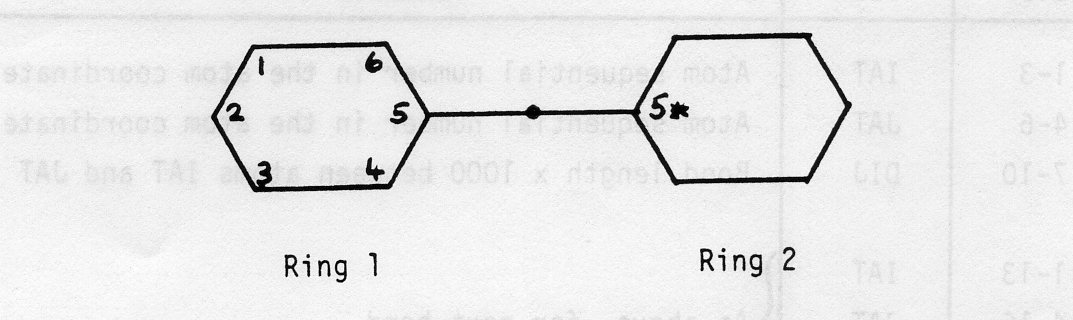
Suppose there is a centre of symmetry at mid-point of bond joining rings 1 and 2.
The asymmetric unit consists of the atoms of ring 1.
However at input time we must input:-
Note that we do not know in advance what label UNIMOL will assign to C5*. It might be C5A, C5B, etc. etc.
Since the label C5* does not appear in the list of atomic coordinates (before or after UNIMOL) a special convention is needed to assign an atom sequential number to this atom in the bond length record.
The convention is as follows:-
(a) If 0 < 0 < 100 Format:  (40I2)
(b) If NAT ≥ 100  Format:  (26I3,2X)
Type (a)
| Cols. | Item | Meaning |
|---|---|---|
| 1-2 | N1 | Sequence of NCON integers N1, N2, ... |
| 3-4 | N2 | |
| etc | etc | etc |
Type (b)
| Cols. | Item | Meaning |
|---|---|---|
| 1-3 | N1 | Sequence of NCON integers N1, N2, ... |
| 4-6 | N2 | |
| etc | etc | etc |
Notes
(i) The crystal connectivity is generated by the UNIMOL program from the atom coordinates and bonding radii. If there are no atomic coordinates NCON=0 and card type 8 is absent.
(ii) The connectivity is described by NCON integers Nl, N2,... The integers are stored in the above formats depending on the value of NAT in the directory card.
The integers are, in fact, the sequential numbers of the atoms in the atomic coordinates list (card type 6).
(iii) The scheme is described, with reference to an example, on the following page:-
Example
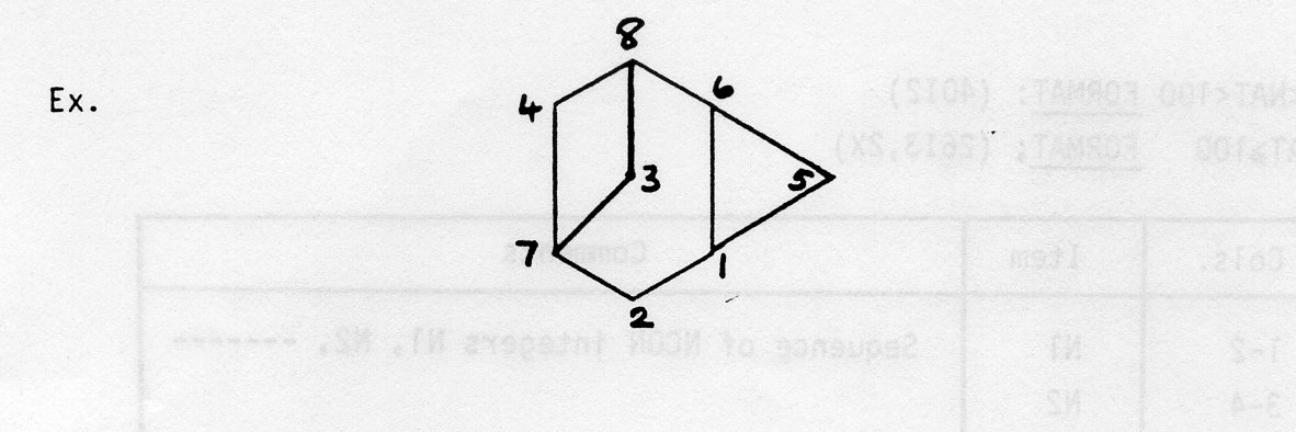
In the diagram the numbers correspond to the sequential numbers of the atoms in the atomic coordinates list.
NAT=8
The first 8 integers in the connectivity list are:-5 1 7 7 6 8 2 4
These indicate atom 1 bonded to atom 5, atom 2 bonded to atom 1 , ... atom 8 bonded to atom 4.
At this stage the bonds 1-6 and 3-8 are undefined.
The next integers in the connectivity list are the pairs of integers needed to define the remaining bonds i.e. 1 6 3 8
In summary, above structure has NCON=12 and its crystal connectivity is:-
5 1 7 7 6 8 2 4 1 6 3 8
Since the order of recording atomic coordinates (basic set) in card type 6 is arbitrary some of the first NAT integers may be zero. These are ignored in decoding the connectivity.
If users wish to assign a residue number to each atom then a subroutine is available in the program PLUTO78.
Two examples of this format are given, which Cambridge usually refer to as FDAT data. The two molecules cited are ACNTBP and BAOXLM which were used for example plots in section 1.2. They are entries numbered 4 and 23 in the dataset. Above each example are column indicators which will enable you to decode the format, using section 4.1, but these are not part of the input.
0        1         2         3         4         5         6         7         8
12345678901234567890123456789012345678901234567890123456789012345678901234567890
#ACNTBP  23740930       19  8  0  0  0  2  4 29  0 18 31132100000010000000000074
 12146 12647  7812    90  9433    90333020 1 1 1 0 1 0134129 14P21/C     440
R=0.045
211 0121 0112 0011 0121 6110 6
C 68H   20N  680  68
Cl     22850 -45440  38580 C10    34740 -77300  37430 C11   24370 -75190  43150
C12    20480 -64970  43620 C13    39360 -88210  36420 C14   31950 -97560  38080
C2     12340 -42040  32760 C3      8870 -31690  33970 C4    16120 -24220  41000
C5     26620 -27140  46900 C6     29940 -37590  45780 C7    26770 -56560  38290
C8     37220 -58670  32790 C9     41100 -68890  32460 H11   19700 -80800  46800
H12    13100 -63400  48100 H14    35500-102700  35900 H141  26300 -97500  27700
H142   28500 -97800  49900 H3      2200 -30300  30600 H4    13600 -17300  41500
H5     32000 -21800  55500 H6     37600 -40000  52500 H8    41500 -53100  28100
H9     48000 -70400  27500 Nl      4470 -49550  24130 O1     5060 -49270  28130
O2      7720 -55490  13300 O3     49090 -89260  34100
 2   51494  3  41378 28 261219  1  71390  1 111404  1 121485 7  81381  8  91376
 9  101374 10 111386 12 131396 12  41392 13 141376 14  21387 2  31394 26  71475
 5   61498  5 291216
7 3  412 2 5 8 91011 1 11213 3 4 6 6 6 8 910111314 72626 5 214
0        1         2         3         4         5         6         7         8
12345678901234567890123456789012345678901234567890123456789012345678901234567890
#BAOXLM  23740930        9  8  0  0  0  4  3  5  3  3  8111100000000100000000074
  1010   796   683    90 12196    90222020 2 2 2 0 0 0343340 12C2/M      440
R=0.086
211 0121 0112 0211 6121 6112 0011 0121 0110 0011 6121 6110 0
BA134C  680  68
BA1   2175    0 3153C1    3615 4030 240501    4133 3346 130502    3102 3300 3516
03    4712    0 2439C1F   3615 5970 240501F   4133 6654 130502F   3102 6700 3516
  2  31240   2 41260  25021550
 0 6 2 2 0 0 6 6
The minimum overlap view is derived by calculating the matrix of inertia using unit weights for all atoms and treating each molecule separately. The principal axes of inertia are found by a subroutine for finding eigenvectors of a symmetric matrix. The axis with the largest latent root is the axis about which the molecular framework has maximum moment of inertia. The rotation matrix for converting the cell orthogonal coordinates to the plotting coordinates is printed.
A test for overlapping atoms in projection is then carried out. Overlap is defined here as a distance of less than 0.25 angstroms between atoms in projection. If no overlap is detected then the program plots the least squares plane view for the molecule without further modification. If overlap occurs then a simple overlap function is calculated to select a view of minimum overlap within +,-30 degrees of rotation from the least squares plane view. The function is:-
F(a1,a2) = Σ Σ dij-2
           i j
for the non-redundant list of distances between atoms i and j in the ZP projection. The rotations are a1 about the XP axis and a2 about the YP axis. Positive rotation is clockwise movement of the atoms when looking along the axis from the positive end towards the origin. It has been found that the minimum position is not greatly affected by truncating the summation with dij less than 1 angstrom and using only points (a1,0) and (a2,0) ( thus saving computing time ). The values a1 and a2 run from -30 to +30 degrees in steps of 10 degrees. The program then orients the molecule at the position on this grid giving minimum F.
The following list consists of the atom type identifiers and their bonding radii, in angstroms, used by the program as default values. Cambridge data format specifies the radius for each atom type, but the calculation of connections for FREE Format data depends on these values unless overridden in the command set, by JOIN and CALC. *** Note : the program only recognises the atom as 1 or 2 UPPER CASE letters.
TYPE  RADIUS   TYPE   RADIUS    TYPE  RADIUS    TYPE  RADIUS
Ac....1.88      Ag....1.59      Al....1.35      Am....1.51
As....1.21      Au....1.50       B....0.83      Ba....1.34
Be....0.35      Bi....1.54      Br....1.21       C....0.68
Ca....0.99      Cd....1.69      Ce....1.83      Cl....0.99
Co....1.33      Cr....1.35      Cs....1.67      Cu....1.52
 D... 0.23      Dy....1.75      Er....1.73      Eu....1.99
 F....0.64      Fe....1.34      Ga....1.22      Gd....1.79
Ge....1.17       H....0.23      Hf....1.57      Hg....1.70
Ho....1.74       I....1.40      In....1.63      Ir....1.32
 K....1.33      La....1.87      Li....0.68      Lu....1,72
Mg....1.10      Mn....1.35      Mo....1.47       N....0.68
Na....0.97      Nb....1.48      Nd....1.81      Ni....1.50
Np....1.55      Pb....1.54      Os....1.37       P....1.05
Pa....1.61       O....0.68      Pd....1.50      Pm....1.80
Po....1.68      Pr....1.82      Pt....1.50      Pu....1.53
Ra....1.90      Rb....1.47      Re....1.35      Rh....1.45
Ru....1.40       S....1.02      Sb....1.46      Sc. ..1.44
Se....1.22      Si....1.20      Sm....1.80      Sn....1.46
Sr....1.12      Ta....1.43      Tb....1.76      Tc. ..1.35
Te....1.47      Th ...1.79      Ti....1.47      Tl....1.55
Tm....1.72       U....1.58       V....1.33       W....1.37
 Y....1.78      Yb ...1.94      Zn....1.45      Zr....1.56
The following hints and tips are intended as a guide to allow you to get the best out of the program and avoid some of pitfalls which occur from time to time. This list is probably incomplete and cannot hope to cover all possible unstable states of the program/ data. However, the program to date has been very robust and its recovery after errors is good. The following tips are intended for terminal use of PLUTO78 unless batch use is indicated.
If your dataset contains more than 1 set of molecular data, you can operate the program in 2 separate ways. The first plots all the data under the control of a single command set, and the second allows you to plot each molecule with different sets of commands. These two methods of working cannot be selected together. To initiate a plot in the first way you use 'PLOT', and in the second you use 'PLOT ENTNO xx' ( where xx is the xx'th molecule in the dataset ). The option of 'ENTNO' is very important in the batch program, and failure to specify it, when many command sets are being used, may result in all subsequent molecules being plotted under its control. This effect will be repeated on any following sets of commands.
Good ball + spoke plots require SEGMENT 20, space filling plots need SEGMENT 50 if unshaded and SEGMENT 150 if half-tone shaded. The default SEGMENT is 8 to enable you to plot quickly. You can use SEGMENT OFF for the highest quality, but the plot will take much longer. In batch, defaults are set up in a different way. All the cameras, except 'hard copy single1, use SEGMENT 50 for most plots, but SEGMENT 150 when the plot is to be space filling and shaded. The 'hard copy single' camera uses SEGMENT OFF exclusively, so that the best possible plots are produced. As a guide, plotting times for 'hard copy many' output of a 30 atom molecule are :-
For 'hard copy single', the output times are:-
*** Note 1 : you can override the defaults on any FR80 camera by using 'SEGMENT xx FR80', where xx is any valid value.
*** Note 2 : remember to scale these times appropriate to the number of atoms in the molecule.
The 35mm cameras take about half the time of the 'hard copy many' output. The 16mm cameras require about half the 35mm times.
Half-tone and colour needs DENSITY 2 for solid shading, but DENSITY -2, -4 will give fast plots for a quick look. On a terminal, with a complicated plot in colour, it may be better to use the values -2 or -4 if you want to take a picture from the screen, or via the DUNN camera at RAL. The FR80 has DENSITY set up to give good full shaded plots using the minimum CPU time.
Plotting a molecule as large as possible needs SIZE 250 SCALE n, where 'n' specifies the scale of the plot in mm per angstrom. The default value will have been given in the last line of output for the previous plot, so you can decide what value 'n' has to be used. The plot has no enclosing box and to remove the title, which may restrict the size of the output, use NOTITLE in the OPT/ GOPT command.
Single plots are 250 units square with no commands output down the right hand side. Nominally the units are in millimetres, but this cannot be guaranteed because of the mapping onto a particular device. With commands output to the plot, the size is reduced to 220 units. The maximum boxed plot is 350 units. Stereo output is 110 units for each plot of the pair and no command output is allowed. The maximum stereo size is 170 units. These sizes refer to tektronix 4010 and sigma devices. On tektronix 4014, On approximately double these sizes.
Do NOT mix CAMBRIDGE and FREE FORMAT data in a single file because the file type will be determined by the first set of data. If this is CAMBRIDGE data then FREE FORMAT will be ignored, and vice versa.
If you use the GEC version and wish to SAVE data in '.PLCOMOUT', 1.FLDATOUT', '.PLXYZOUT','.PLANGOUT', then ALWAYS copy these files before running PLUTO78 again. This is a precaution because the MACRO empties these files at the start of each run. On CMS, the 'XYZOUT DATA' and 'ANGOUT DATA' files are not user definable and may be overwritten on each run.
When using the Sigma colour terminal (5660) on the GEC's you can use the terminal hardware to change the colours displayed on the screen. To do this let the current plot finish, and then type the <return> key to obtain the 'COMMAND?' prompt. Type in the following character string:-
+-*/JGxabc0<return>
where 'x' is the GINO colour number and 'abc' the hexadecimal value of RED, GREEN and BLUE to be output. Each of a,b,c can have the values 0,1,2,3,4,5,6,7,8,9,A,B,C,D,E,F. 0 is for zero output and F the maximum. The current GINO colours are:-
BLACK (C)  = 0,  CYAN (BR)   = 1, YELLOW (S)= 2,
GREEN (CL) = 3,  MAGENTA (P) = 4,  BLUE (N) = 5,
RED (O)    = 6,  WHITE (H)   = 7
The labels in brackets are the atom types which go with the colours. To change the oxygen atoms from red to orange type in:-
+-*/JG6FC00<return>
Cambridge commands are indicated by a 'C' in the command name column, and additional RAL commands by 'R'. A summary of the Options Keywords and Qualifier command names follows :-
OPT  COMMAND   KEYWORD   MEANING
00C)..OPT.......................Set up default options.
01R)............ANGLE...........Calculate bond angles and print them out.
02C)............CELLPLOT........Plot outline of unit cell.
03C)............DEBUG...........Invokes debugging facility.
04C)............NOHYD...........Omit all H atoms.
05C)............NOLABEL.........Suppress all labelling.
06R)............NOTITLE.........Suppresses output of title.
07C)............PACK............Plot packing diagram.
08R)............PFRED...........Print free format data on terminal when input
                                is from disk.
09C)............SEPRES..........Treat each bonded residue by itself.
10C)............SOLID...........Plot ball + spoke model.
11C)............STEREO..........Plot side-by-side  stereo pair.
12C)............VIEWS...........View  down shortest of XO,YO,ZO.
12C)............VIEWX...........View along XO.
14C)............VIEWY...........View along YO.
15C)............VIEWZ...........View along ZO.
16C)..C.........TEXT............Comment record.
17C)..CALC......BOTH............Calculate connectivity.
18C)..COLOUR....KEYWORDS........Specify colour of lines for plotting.
19R)..DCLEAR....NONE............Erase current Free-format data-in-core and reset
                                flags and variables for next set of data.
20R)..DIRCOS....KEYWORDS........Specify a vector within the molecule and calculate
                                its direction cosines, or form a right-handed set of
                                axes, or calculate the crystal diamagnetic susceptibility.
21R)..DIST......BOTH............Specify two atoms and find the distance  between them,
                                or define plotting of the distance on the device.
22C)..EXCL......KEYWORDS........Exclude the specified elements.
23R)..FR80......NONE............Send current commands/ data to file.
24R)..HELP......KEYWORDS........Invokes the help facility.
25C)..INCL......KEYWORDS........Include the specified elements.
26C)..JOIN......KEYWORDS........Specify connectivities.
27C)..LABEL.....KEYWORDS........Plot specified element labels only.
28C)..MATRIX....VALUES..........Specify rotation matrix.
29C)..MOLE......VALUES..........Specify molecules for packing.
30C)..PERSP.....VALUES..........Plot with perspective.
31C)..PLOT......BOTH............Initiate plotting.
32C)..PRINT.....................Print out geometry + connectivity.
33C)..RADII.....BOTH............Specify radii of atoms, bond cylinders, or the inclusion
                                of a stick plot overlaid on a space filling plot.
34C)..RANGE.....VALUES..........Specify range of unit cell for packing.
35C)..SHADE.....VALUES..........Shade atom circles.
36C)..STEREO....COLOUR..........Specify red/ green stereo pair.
37R)..STEREO....VIEWER..........Specify Open University stereo pair.
38C)..STOP......NONE............Closes output files + stops program.
39C)..TITLE.....TEXT............Print specified title at top of plot.
40C)..VIEW......BOTH............Specify view direction.
These commands remain in force over many plots unless reset by the GLOBAL options command GOPT (which has the same keywords as OPT), or changed by using the command to redefine keywords and values. As in the case of the LOCAL command, GLOBAL ones are distinguished by 'C' for Cambridge and 'R' for RAL. A summary of the GLOBAL command names follows :-
COMMAND NAME  KEYWORDS         MEANING
              +VALUES
00R)..GOPT........SAME.AS.OPT...Set up  default options.
01R)..COLOUR........KEYWORDS....Specify atom/ colour pairs.
02RJ..COMPLOT.......KEYWORDS....Commands are listed on the plot.
03R)..DEMO...........VALUES.....Set up a continuous demonstration with
                                a variable amount of time between plots.
04R)..DENSITY........VALUES.....Specify the spacing  of lines which shade atoms.
05R)..INTENSITY......VALUES.....Set up scaled intensities for all colours on FR80.
06R)..INTHIT..........BOTH......Set up absolute intensities + hits of colours on FR80.
07R)..MANYUP.........VALUES.....Set up the FR80 hard copy many subdivisions.
08R)..MOVE............BOTH......Allows you to move molecules within the unit
                                cell and move the origin of the whole plot.
09R)..ROTATE..........BOTH......Specify bond rotation.
10R)..SEGMENT.........BOTH......Specify the  number of segments in the atom circles.
11C)..SIZE............BOTH......Set up the size of the plot.
