
The FONTS program's major purpose initially was to provide an easier means of defining character fonts than the ones currently used in the GROATS system. It allows the user to define and modify individual characters until they are acceptable. They can then be output in a suitable form for inclusion in a GROATS font. A second use of the system, which may well be as important as the first, is to use the generated characters in defining slides or film titles. This facility does allow the general user to make slides with very little effort.
The program consists of six overlays. Communication between overlays is completely by data files on peripheral devices. The six overlays are:-
This program defines individual characters and stores them on the peripheral device associated with DAT slot 2 (in future this will be written device 2).
This program takes a set of characters defined on device 2 and produces a complete character font on device 1. The program allows existing fonts to be clanged or extended.
This program uses a previously defined font on device 1 to generate a set of individual frames made up of characters which are stored on device 3.
This program takes previously defined frames and generates an SD4O2O tape. The frames can be output in the form required for slides requiring one or two 35m frames or alternatively in a form required for film titles. The magnetic tape is device 7.
Individual characters defined on device 2 are output on device 5 in the form required by the GROATS system.
Individual characters defined on device 2 are output on device 5 in the form required by the SPROGS system.
The FONTS program is available as an 'Execute' file on the disc under user FRA. Also available is the standard HELVETICA font which is numbered 1. Additional fonts may become available later, Printing out the directory will indicate the fonts currently available. Each font is stored in a file having the title
XXFNTA DOC
where XX can be any two digits indicating the font number. Thus the HELVETICA font is stored in the file 01FNTA DOC.
The basic set of DAT slots needed to be set up before entering the program is as follows:-
  A DK <FRA>     -4
  A TTA           4
  E FONTS
Additional DAT slots must be assigned. These depend on which overlays are going to be used:-
DF CHAR         2, 6, 10
PACK FNT        1, 2
DF FRAME        1, 3, 6, 10
OUTPUT FRAME    1, 3, 7
PUNCH CHAR      2, 5
SPRG            2, 5
The possible assignments are:
1, 2, 3      DT or DK
 5           TTA or PP
 6           LT0
 7           MTA1
10           VTA
Some examples of possible assignments are:-
(1) Defining individual characters on DT2
A DR2/DK <FRA> -4/TTA 4/LT0 6/VTA 10
(2) Using characters defined on DT2 to generate a font on DT1
    A DT1 1/DT2 2/DK <FRA> -4/TTA 4   4/LTO 6/VTA JO
    E FONTS
(3) Using the standard Helvetica font to generate frames on the disc
    A DK <FRA> 1/DK <FRA> -4/DK 3/TTA 4/LT0 6/VTA 10
    E FONTS
(4) Using the standard Helvetica font and frame definitions on DT3, generate a SD4020 tape on unit 1
    A DK <FRA> -4/DK <FRA> 1/DT3 3/TTA 4/MTA1 7
    E FONTS
(5) Output onto punched paper tape the characters defined on DT2
    A DK <FRA> -4/DT2 2/TTA 4/PP 5
    E FONTS
As soon as the program is entered, the following line will be printed on the teletype:
DF CHAR, PACK FNT, DF FRAME, OUTPUT FRAME, PUNCH CHAR, SPRG, I1
This is a request for the user to input a number between 1 and 6 followed by NEWLINE to indicate which of the six overlays is to be entered.
Each overlay has a method of returning to this top level so that another overlay can be selected later.
The overlay DF CHAR allows the user to define individual characters and store them on device 2. Characters can be recalled and modified at a later date. Interaction with DF CHAR is achieved by sitting at the display and using light pen, pushbuttons and display keyboard, At any time the program is in a state expecting a pushbutton hit, a line to be input from the display keyboard or a light pen track. In the light pen tracking mode the light pen is used to move an octagon on the screen. When it is located in the desired position, push button 5 is hit to change the state. At any point the next action required is indicated on the mid-left of the screen:
(1) Pushbuttons: WAITING FOR INPUT
                 FROM PUSHBUTTONS
appears on screen
(2) Keyboard:    WAITING FOR INPUT
                 FROM KEYBOARD
appears on screen
(3) Light pen:   WAITING FOR INPUT
                 FROM LIGHTPEN
appears on screen.
Pushbutton 5 causes tracking octagon to appear and disappear.
The program consists of basically three levels with the different levels associating different meanings to the pushbuttons hit. At the top level the program is initialised, on the middle level individual characters are accessed, on the lower level a particular character is defined or manipulated. At each level the meaning associated with each push button is displayed at the bottom of the screen.
The push button (PB) controls are as follows:-
     TOP LEVEL       MIDDLE LEVEL         BOTTOM LEVEL
PB1   XFIDUC          GET CHAR            DELETE ALL
PB2   YFIDUC          PUT CHAR            DELETE INSERT
PB3   INIT            DOTTED NOT          DOTTED NOT
PB4   DISPLAY FONT                        SEEN NOT
PB5   DOWN            DOWN
PB6   QUIT            UP                  UP
Individual characters are defined on a mesh WIDTH units wide and HEIGHT units high. The character is assumed to sit on a base line and can be up to HEIGHT units above the line and 0.5 HEIGHT units below the line, The character is assumed to start on the base line at the left of the character. The character is made up from a sequence of lines where the end point of the previous line is the starting point of the current line. Lines may be either visible or invisible. Invisible lines can be 'seen' by showing them on the screen as dotted. The character must finish on the baseline but not necessarily at the right hand end. For example, the character V on a 4 × 4 mesh might be defined as:-
The four lines in the definition of V are:-
(1) AB invisible
(2) BC visible
(3) CD visible
(4) DE invisible
The program is entered at the top level and requires to know the size of mesh to be used in the character definitions. At the top level initially the meaning of the various pushbuttons is indicated together with a message noting that the system expects a pushbutton to be hit. The meanings of the top level pushbuttons are as follows:
PB1: X FIDUC
To aid in defining characters, the mesh in the X and Y directions can be broken up by allowing lines at regular intervals to be intensified (the standard graph paper technique of marking every 5th or 10th line).
If the XFIDUC button is pressed, a message
X FIDUCIAL =
appears at the top left of the screen and a number is expected to be input on the display keyboard. Inputting the number N will cause every Nth vertical line in the mesh to be overstruck.
Once the number has been entered, the program returns to the top level expecting another pushbutton to be hit. The number read in is displayed on the screen.
PB2: Y FIDUC
Similar to X FIDUC but defines which horizontal lines in the mesh will be overstruck.
PB3: INIT
The program expects the mesh size to be specified by first typing the mesh WIDTH fol1owed by the mesh HEIGHT. As soon as PB3 is hit, the message:-
FONT WIDTH =
appears and the number is required to be input at the display keyboard. The number read in will be displayed on the screen. The message:-
FONT HEIGHT =
appears and the required number must be entered at the display keyboard. Once completed the number will appear on the screen and the program reverts to the top level expecting another pushbutton hit.
PB4: DISPLAY FONT
This option allows a previously defined set of characters to be displayed on the screen. The characters numbered 1 to 64 are displayed on the screen in rows. The usefulness of this facility is less now that the user has the capability to define frames of any set of characters using the DF FRAME overlay.
PB5: DOWN
This changes the state of the program to the Middle level. The bottom of the screen is updated to display the new meanings of the pushbuttons.
PB6: QUIT
The program exits from the DF CHAR overlay and returns to the point where it was entered originally.
A likely set of operations at the Top Level might be:
(1) HIT PB3
(2) INPUT FONT WIDTH= 32 AT KEYBOARD
(3) INPUT FONT HEIGHT= 32 AT KEYBOARD
(4) HIT PB 1
(5) INPUT X FIDUCIAL= 8 AT KEYBOARD
(6) HIT PB2
(7) INPUT Y FIDUCIAL = 8 AT KEYBOARD
(8) HIT PB5
This initialises the system to generate characters on a 32 × 32 mesh. When the mesh is displayed, every 8th line both horizontally and vertically will be overstruck.
N.B. PUSHBUTTONS
The pushbuttons on the PDP15 display are notorious for not working every time. If nothing happens when a pushbutton is hit, continue hitting it until the required action takes place.
N.B. DISPLAY KEYBOARD
The program will ignore all characters, other than digits that are pressed. The program expects a NEWLINE key to be pressed at the end of a number.
When the program is in the Middle or Lower Levels, a mesh is displayed on the right hand side of the screen. The lines making up the character will be shown with reference to this mesh. The mesh will be WIDTH units wide and HEIGHT units above the base line and 0.5*HEIGHT below the baseline. The baseline is indicated by extending the line from the mesh.
Individual characters are numbered from I upwards. Although the numbers need not have any particular significance, it is usual to have the numbers either equal to the equivalent GROATS number or alternatively the PDP15 internal number equivalent to the character. Characters are stored on device 2 as files, one file for each character. The characters have file names:-
XXCHAR DOC
where XX defines the character number. Thus character | is stored as file:-
01CHAR DOC
The Middle Level, when entered from the Top Level, always attempts to read the character numbered 1 from device 2. Assuming no character yet exists, nothing is displayed. If the character 1 exists, it is displayed on the mesh showing the individual lines making up the character. In addition three small copies of the character appear on the left of the screen. These are 1, 2 and 3 times the basic raster size of the character. For example, a character defined on a 32×32 grid will be displayed having height and width 32, 64 and 96 raster positions respectively.
The pushbutton operations on the Middle Level are as follows:
PB1: GET CHAR
The program expects the character number required to be input from the display keyboard. The equivalent file is located on device 2, read down and the character displayed on the mesh.
PB3: DOTTED NOT
The pushbutton determines whether or not the invisible lines making up the character will be displayed as dotted lines or not shown at all. Underneath the display for the pushbutton, the current mode setting is indicated. When the Middle Level is entered initially, the invisible lines are not displayed.
PB4
Not used
PB5: DOWN
Program enters the Lower Level for character manipulation
PB6: UP
Program returns to the Top Level.
N.B. If the characters are stored on DEC tape, it takes an appreciable time before the required character is accessed from or entered on the DEC tape. The correct operation of the pushbutton can be seen as the DEC tape will start to move immediately.
Defining or updating a particular character is carried out at the Lower Level. All operations apply to the character currently defined by the Middle Level. The pushbutton operations on the Lower Level are:
PB1: DELETE ALL
The character currently being examined is forgotten and a new definition is expected starting again.
PB2: DELETE INSERT
This pushbutton defines the current mode of operation. On entering the Lower Level, the INSERT mode is always selected. The current mode setting is indicated on the display under the pushbutton name.
PB3: DOTTED NOT
This has the same meaning as PB3 on the Middle Level. It determines whether or not invisible lines making up the character will be displayed as dotted lines or not shown at all. The current setting is carried down from the Middle Level and returned to it on exit.
PB4: SEEN NOT
This pushbutton defines whether the lines being added to the character are visible or not. The current mode setting is indicated on the display under the pushbutton name.
PBS:
This pushbutton activates the tracking octagon. Inserting character lines will be discussed below.
PB6: UP
Returns control to the Middle Level.
A character is defined as a set of lines starting at the left hand end of the base line. Assuming a character is being input initially, the first line will be entered by setting the INSERT mode using PB2 and the correct mode SEEN or NOT by PB4. The pushbutton PBS is then pressed and the tracking octagon will appear. Move the octagon, using the light pen to the vertex of the mesh where the next line is to end. Once it is positioned correctly, hit PBS again. The octagon will disappear and a line will be entered for the character starting at the initial position and finishing at the position reached by the octagon. If the line is to be visible, a full line will be displayed on the mesh and also on the three character representations. If the line is invisible, then whether it appears on the mesh will depend on the current setting of PB3.
The next line to be added to the character is achieved by setting the correct mode using PB4 and hitting PB5 once more to retrieve the octagon. For example, the character V might be defined, starting at the Middle Level, as follows:-
(1) Hit PB1. Input the number associated with the letter V. The device 2 will be searched and we shall assume the character V does not exist. No character will be displayed.
(2) Hit PB5: Down to the Lower Level.
(3) Hit PB1: Ensures that character is being started from scratch by deleting all.
(4) Hit B3: Sets mode to DOTTED ensuring that invisible lines will be displayed.
(5) Hit PB4: Sets mode to NOT SEEN.
(6) Hit PB5: Tracking octagon appears. Move it to top left and hit PB5 again. Vertical dotted line appears from left end of base line to top left corner of mesh.
(7) Hit PB4: Sets mode to SEEN.
(8) Hit PB5: Tracking octagon appears at top left. Move it, using light pen, to middle of base line. Hit PBS again. Tracking octagon disappears and line (not dotted) appears on mesh. Three lines (one for each size) appear on middle left of screen.
(9) Hit PB5: Tracking octagon appears again. Move it to top right. Hit PB5. Second line of V appears. Tracking octagon disappears. Complete V appears on left, 3 sizes.
(10) Hit PB4: Sets mode to NOT SEEN.
(11) Hit PB5: Tracking octagon appears. Move it to right end of base line. Hit PB5 Tracking octagon disappears. Dotted vertical line appears.
(12) Hit PB6: Returns to Middle Level.
(13) Hit PB2: Puts definition of letter V away on device 2.
A character, already defined or in the process of being defined, can be modified by deleting some of the existing lines and replacing them by others. The user must be conscious of how the character was defined initially. Each character consists of a set of lines, say AB, BC, CD, DE, EF, FG where Z = G denotes the end of the character. At any stage in the modification of a character, not more than one gap can appear in the chain of lines making up the character. Let us denote the start and end of the gap by X and Y respectively. For example if the line BC is deleted, the character will then consist of
AB, CD, DE, EF and FG where X=B Y=C and Z=G
An attempt to delete another line which would create a second gap is not allowed. Thus deleting DE or EF is not allowed. However CD could be deleted leaving
AB, DE, EF and FG with X=B Y=D and Z=G
alternatively FG could be deleted leaving
AB, CD, DE, EF where X=B, Y=C, Z=F
Lines are deleted by setting the mode to DELETE (using PB2 at the Lower Level) and then pointing at the line to be deleted using the light pen. A light pen hit will cause the line to disappear. Any number of lines can be deleted in this way as long as not more than one gap appears in the original character. Invisible lines can only be deleted by setting the DOTTED mode.
New lines can now be inserted using the method outlined above for defining characters. The only difference is that, with a new character lines are always inserted at Z, the end of the character.
If a gap exists in a character when a line is being inserted then the line is added from the position X to the current position. Lines will continue to be inserted in the gap until the tracking octagon is moved to the point Y defining the end of the gap. Once the gap is removed, additional lines will be entered at the end of the character, Z, onwards.
The following error exits can occur from DF CHAR :-
(1) There is a limit on the size of mesh allowed. 5 * HEIGHT + 4 * WIDTH < 500
(2) The number of lines in any character must be less than 125.
(3) Numbers input from the display keyboard must have at least one digit. Only the first three digits are used. The remainder are ignored.
The overlay PACK FNT, allows the user to pack up a set of characters already defined by DF CHAR into a font to be used with later overlays. Characters in the font are accessed using the display keyboard. The @ key is used as a shift character (see DF FRAME). The set of possible characters to be defined are:-
Number   Character
1 - 26   A-Z
27       [
28       \
29       ]
30       ^
31       _
32       Space
44       ,
45       -
46       .
47       /
48       0
49       1
50       2
51       3
52       4
53       5
54       6
55       7
56       8
57       9
58       :
59       ;
65-69    a-z
91       {
92       :
93       }
94       ~
108      <
109      =
110      >
111      ?
113      !
114      '
115      #
116      $
117      %
118      &
119
120      (
121      )
122      *
123      +
There is no need, of course, for the character associated with a particular key to have the appropriate form. The character forms are stored in an array by PACK FNT with a directory at the front giving the starting positions of the individual characters. Before a font can be defined it is therefore necessary to define the size of the directory. This will normally be 128 but it could be 64 if the Upper Case set of characters only are to be accessed.
On entry to PACK FNT, the program prints
INIT = I, GET = 2, PUT = 3, PRINT = 4, ADD = 5, RETURN = 6, I1
on the teletype. This requires the user to indicate by inputting a digit between 1 and 6 which of the options is required. All responses are on the teletype and require a NEWLINE to be typed afterwards. Each command from PACK FNT indicates the FORTRAN FORMAT of the required response. The six possibilities are:-
(1) INIT
The system response is
FONTAR INITIALISED, MXCHR = I3
It requires the user to define the size of the directory. This will usually be 64 or 128 (I3 FORMAT). The program then returns to the main level.
(2) GET
The program will input an already defined font from Device 2 for additions or amendments. The program types
INPUT FONTAR FROM DT1 FILE NAME XXFNTA, XX = I2'
The user is required to type the number of the font which is to be input.
(3) PUT
The program will output the font defined to device 2. The program types:-
OUTPUT FONTAR TO DT1 FILE NAME XXFNTA, XX = 12
The user is required to type the number of the font which is to be output.
(4) PRINT
The contents of the font array can be output to check the correct form. This is mainly a debug aid. However, as the directory is printed first, it can be useful to the user as a check that the characters he desires are present. It also indicates how much of the font array is already used up. The program prints:
PRINT FONTAR MXCHR = NNN FNTNX = MMM MAX PRINT = I5
The number printed NNN is the length of the directory while MMM indicates how much of the font array is already used up. The font array can have at most 3000 entries. The user is required to type how many elements of the array he requires to be output. The array is output 10 per line. The first position printed indicates the position in the array of character 1 and so on.
(5) ADD
This is the main option and defines how individual characters stored on device 2 can be added to the current font. The program types:-
ADD CHAR(DT2) I TO J INTO FONTAR K ONWARDS
I= I3, J= I3, K= I3
Thus a set of characters defined as I, I+1, I+2 .. J on device 2 are added to the font in positions K, K+1 and so on. The user must type in his response as required.
(6) RETURN
The program returns to the master level ready to enter another overlay.
Consider the following example. A user has a set of lower case letters defined as characters l to 26 which he wishes to add to an already defined font 1. The new font is to be given the number 2.
The likely dialogue is :-
INIT = 1, CET = 2, PUT = 3, PRINT.= 4, ADD= 5, RETURN= 6, I1
2
INPUT FONTAR FROM DT1 FILE NAME XXFNTA, XX = I2
1
INIT = 1, GET= 2, PUT = 3, PRINT = 4, ADD= 5, RETURN= 6, I1
5
ADD CHAR (DT2) I TO J INTO FONTAR K ONWARDS
I= I3, J= I3, K= I3
  1 26 65
INIT = 1 , GET = 2, PUT = 3, PRINT = 4, ADD = 5, RETURN = 6, I1
3
OUTPUT FONTAR TO DT1 FILE NAME XXFNTA, XX = I2
2
INIT = 1, GET = 2, PUT = 3, PRINT= 4, ADD= 5, RETURN= 6, I1
6
If a character already defined in a font needs to be altered, all that is required is to add the character again. The space used for the first definition of the character is not reclaimed, Consequently if this is done frequently the font array will be filled up. The user will then have to generate the font again starting from an initialisation.
The program checks each character for consistency when it is added to a font. It is possible to get the following error message
CHARACTER NNN IS ILLEGAL MMM
The character NNN is badly formed and is not added to the font. Other characters requested to be added will be entered. The digit MMM indicates the type of error
MMM = 1
The end of the character is not on the base line
MMM = 2
A gap still exists in the character.
In both cases the remedy is to correct the offending character.
This overlay allows the user to make up frames of characters from a previously defined font. The user defines his actions using a set of light buttons in the offset region of the display. The main display area is used to present the required frame. Apart from an optional border, all information in this area will appear on the final frame.
As soon as the overlay is entered, the message:-
FRAME OUTLINE, 0 = TITLE, 1 = SINGLE, 2 = DOUBLE, 3 = NONE, I1
is output on the teletype. The user types on the teletype the required integer to define a border surrounding the frame.
TITLE
An area 1000×750 is marked in the centre of the frame.
SINGLE
The full display area can be seen in a single frame slide.
DOUBLE
Only a proportion of the total area can be seen in a double frame slide. This is marked. The user should remember that the relative size of the slide will be twice that of the SINGLE case. It is possible to mount a slide so that some area outside this frame is visible but this will require care in the mounting.
NONE
No guide border is displayed.
Once the response to this message has been given, the display will appear with the following information :-
The lines FILE NO= and FRAME= will display the number of the font being used and the frame number that is being worked on. The message KEYBOARD will sometimes be replaced by LIGHT PB. This indicates whether a line of type is expected from the display keyboard or alternatively a light pen pick or pushbutton hit.
The system is entered expecting the number of the font to be used to be entered at the keyboard. Once this has been done the program is ready to obey one of the commands given on the right. It is activated by a light pen hit on the desired line of text. The user can see that a particular command has been activated as it will blink for a short period before obeying the command. Activating the first six options (TRACKXY, SIZE, INPUT TXT, OUT FRAME, IN FRAME, RETURN) can also be achieved by hitting the pushbuttons PB1 to PB6 respectively.
The user is attempting to define a number of frames each of which consists of a number of items. An item consists of a line of characters. The user can define the starting position of the item and how large the characters will be. The item currently being worked on will blink on the screen. To select a different item to work on, the light pen can be pointed at the text making up the required item. This will then start blinking. A completely new item can be defined by hitting the NEW ITEM light button.
The actions of the individual light buttons are as follows:
NEW ITEM
This selects a New Item to work on. The origin and size of the New Item is initialised to be the same as the previous item defined.
TRACKXY
The octagonal tracking cross will appear. It can be moved to any position on the display and will indicate the starting position of the currently selected item. If the text of the item already exists, the pushbutton hit which turns the tracking octagon off will cause the display to be updated. The text does not move with the tracking octagon. The initial position of the tracking octagon will be the current starting position of the text of the item if it exists. Alternatively if it is a NEW ITEM, the tracking octagon will be at the origin of the previous item defined. This can be quite useful if a set of items are to be defined whose positions relate to each other. The user should hit pushbutton 1 to turn the tracking cross off.
SIZE
Hitting the light button SIZE will cause the program to expect a number to be input on the display keyboard indicating the size of the current item. The basic size has a parameter setting equal to 16. Resetting the size parameter to 32 will cause characters to appear twice as 1are. Resetting the size parameter to 8 will cause characters to appear half the standard size. The standard size is where the mesh size is translated directly into raster positions. Thus characters defined on a 32×32 mesh will be 32 raster positions in height and width for the standard size (parameter = 16).
INPUT TXT
Hitting this light button will cause the program to expect a line of text from the display keyboard. This is to replace the text already defined for the selected item. The standard case characters are input by pressing the relevant key. The lower case alphabet and characters on the same shift are entered using the @ character. The @ character is used to change case in either direction. For example:-
A @ B @ C @ 4 @ 4
  will generate
A b C $ 4
Each line of text is assumed to start in the standard case.
OUT FRAME
The frame just defined is stored on device 3 as file XXFRAM DOC where XX is the number of the frame. The next frame number is selected and its contents initialised to a null frame.
IN FRAME
The program expects the number of the frame to be input on the keyboard. This frame is read down from device 3 and displayed.
RETURN
The program returns to the master level to enter a new overlay.
NEW FRAME
The program expects a number to be input from the display keyboard which replaces the existing number associated with the frame. To define a frame similar to an existing frame would be done by reading the frame down using IN FRAME, changing the number by NEW FRAME and putting it back on the device with OUT FRAME.
TRACK X
Similar to TRACKXY but tracking of octagon is constrained to the X-direction.
TRACK Y
Similar to TRACKXY but tracking of octagon is constrained to the Y-direction.
DOWN
The position of the currently selected item is moved down by the amount Y-INCREMENT. This is initialised to 32 raster positions. The command is useful if a number of items need to be aligned carefully. The amount moved is modulo 1024.
RIGHT
Similar to DOWN but moves the item right by X-INCREMENT.
Y INCRMNT
The program expects a number to be input from the display keyboard which replaces the current value of Y-INCREMENT
X INCRMNT
Similar to Y INCRMNT but changes the value of X-INCREMENT. These two allow the user to effectively define his own horizontal and vertical tabs. For both DOWN and RIGHT the reverse operation can be achieved by defining a large value for the increment. To move left by 24 raster positions would require a value of X-INCREMENT equal to 1000.
This overlay takes previously defined frames and outputs these to magnetic tape in a form suitable for the SD4020. The program uses frames, previously defined, on device 3 and a font previously defined on device 1. It is usual, but not essential, for the font used in the frame definitions to be the same as the one used in the output to magnetic tape. The magnetic tape should be loaded on one of the tape decks and the unit number set to 1.
On entry the program prints on the teletype
START
The magnetic tape on unit 1 is initialised by the output of a record containing
ADVFLM
EXPAND IMAGE
IGNORE REST OF RECORD
The program then types:-
INPUT FONT NUMBER, I2
The user is expected to type on the teletype the number of the font (I2 format) which has been previously defined on device 1. The program then prints:-
TYPE OF OUTPUT, 0 = TITLE, 1= SINGLE, 2 = DOUBLE, 3 = RUNOUT, I1
The user is expected to input on the teletype the format he requires for the frames being output.
TITLE: the frames are output in a form applicable for a film title.
SINGLE: each frame is output in a form suitable for a 35mm slide. A blank frame is inserted after each slide frame.
DOUBLE: each frame is output in a form suitable for a 35mm slide. The frame is split over two 35mm frames and, assuming the SD4020 is correctly set up, these will touch, thus giving a much larger image than is possible in the SINGLE mode.
RUNOUT: a blank frame is output.
In the first three cases, an IGNORE REST OF RECORD order follows the ADVFLM so that frames are not split across records.
Once the type of output is defined, the program prints
NUMBER OF COPIES OF EACH FRAME, I4
The user then inputs on the teletype the number of copies of each frame required (I4 format). If RUNOUT has been selected, the program outputs that number of ADVFLM orders followed by an IGNORE REST OF RECORD.
In the other cases, the program prints:-
FRAME MIN AND MAX, 2I3
The user inputs at the teletype (2I3 format) the number of the first and last frames to be output. These should have been previously defined on device 3. The program then outputs to magnetic tape each frame the specified number of times.
Once these have been output, the program prints:
FILEMARK, ENDTAPE, AGAIN, I1
The user inputs the digit 1, 2 or 3 (I1 format) depending on the option required.
FILEMARK: the program outputs a filemark and returns to the start ready to output additional frames.
ENDTAPE: the program outputs four filemarks and returns to the main program.
AGAIN: the program returns to the start ready to output additional frames.
This overlay allows the user to output characters, previously defined on device 2, in a form ready to be input to GROATS. On entry, the following message is printed:-
1906A USER
The user is required to type his 1906A user number in the first positions of the line. For example:-
GSIN02
Once this has been input, the program punches a heading suitable for defining a 1906A file with the name FONTCHARS. The user should ensure that he does not have a file with this name before entering the file into the 1906A.
The program then prints:-
FONT HEIGHT, I3
The user is required to enter the font height used during the character definition.
The program then prints
DEFINE CHARS TO BE OUTPUT IMIN, IMAX, IDSP 3I3
The user is required to type the starting and finishing numbers of the characters to be output. These will be output as GROATS characters IMIN + IDSP to IMAX + IDSP. For example, typing :-
3 7 2
would cause the characters defined as 3, 4, 5, 6 and 7 on device 2 to be output as characters 5, 6, 7, 8 and 9 in the GROATS format (see GROATS manual).
Once the characters have been output, the program prints
AGAIN= 0,FINISHED = 1, I1
Typing 0 will cause the program to cycle back to the main message ready to output some additional characters. If 1 is typed, the input document for the 1906A is completed.
This overlay allows the user to output characters, previously defined on device 2, in a form ready to be added to a SPROGS program. The output consists of calls to routines in SPROGS for picture file definition. On entry the following message is printed:-
1906A USER
The user is required to type his 1906A user number in the first positions of the line. For example:-
GSIN02
Once this has been input, the program punches a heading suitable for defining a 1906A file with the name FONTCHARS. The user should ensure that he does not have a file with this name before entering it in the 1906A.
The program then prints:
INPUT FONT NUMBER, I2
The user is required to type the SPROGS file number to be associated with the characters (a CALL NUMBR is added in front of each character).
The program then prints:-
DEFINE CHARS TO BE OUTPUT IMIN,IMAX,IDSP, 3I3
The user types the starting and finishing numbers of the characters to be output, These will be output as characters having the GROATS position IMIN+IDSP to IMAX+IDSP. For example to output the character defined as 27 so that it is equivalent to an 'A' would require
27 27 6
as character 33 is A in the SPROGS set. This will cause
CALL STDF (ANAME('A'))
to be generated. This is followed by the relevant calls to TODXY and UPDXY and terminates with a call to FIDF.
Once the characters have been output, the program prints:-
AGAIN = 0, FINISHED = 1, I1
Typing 0 will cause the program to cycle back to the main message ready to output some additional characters. If 1 is typed, the input document for the 1906A is completed and control is returned to the top level.
The compiled program is available on the PDP15 disc under the FRA directory. The source routines are stored on Dec tape 408 and the individual compiled routines are on Dec tape 409. The system is compiled by:-
$A DT2 - 4
$A DK <JRG> - 5
$CHAIN
CHAIN VTA
NAME XCT FILE
>FONTS
LIST OPTIONS AND PARAMETERS
>
DEFINE RESIDENT CODE
>MAIN, SMALLR, TELT, INBITS, MODFLN, NRINT, .DA
DESCRIBE LINKS STRUCTURE
>CH1 = MNFONT/PRESRV, UPDTXT, UPDOT, ACTION, NUMBUF, OUTNMB,
-DELCHR, LTPNCH, PUTCHR, GETCHR, UPCHR, CHRDSP, UPFNT,
-BLMAIN, BLFONT, BLXYTX
>CH2 = MNPKUP/GETCHR, PUT, DELCHR
>CH3 = MNFRAM/UPFRME, INFRM, DEFITM, GETNMB, OUTCHR,
-NEXTCH, OUTNM, OUTFRM, BLAA
>CH4 = MNDSFR/DSPCHR, INFRM, IGRSRD, TOBUF, ADVFLM, TODXDY,
-SEEVEC, DRAWVC, SLCTCM, MAGTAP
>CH5 = FNTOUT/GETCHR, DELCHR
>CH6 = SPRCOT/GETCHR, DELCHR
>CHI : CH2 : CH3 : CH4 : CH5
>
The emphasised are the system responses. The library file <JRG> used contains a version of TRACK which does not use the parameters in VTA. by name. The version of .DA is JRG's own special version.
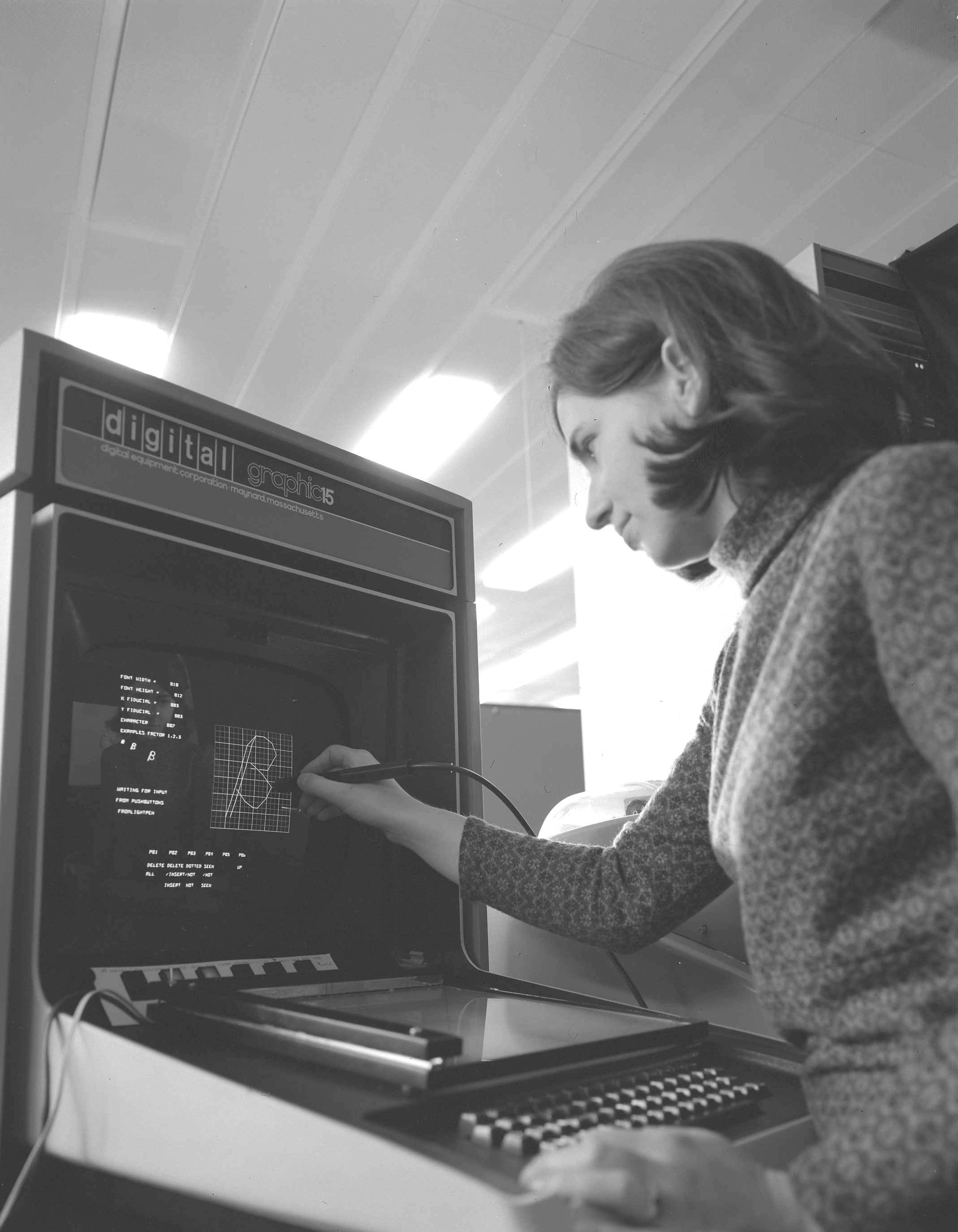
Susan Hockey using the font generation program, 1972
