
The arithmetical facilities specified as being desirable in the previous lecture are relatively modest, and their engineering is a straightforward procedure. The design and construction is also simplified by the adoption of the binary notation. The laws of binary arithmetic are particularly simple to apply, as will be shown later in this lecture.
The logic of the arithmetical operations becomes rather more complicated when attempts are made to reduce the limitations incurred by the use of a constant length of number in the number store. In a normal computer using, for instance 30 binary digit numbers, an addition process can produce a 31 binary digit sum, and one digit in this number must of necessity be rejected. The easiest course for the engineer to adopt is to ignore the most significant digit in the overflowing number, the user is then obliged to examine his quantities, and ensure that these lost digits are always zeros and are therefore not significant. The majority of computers installed in this country operate with a so called fixed point arithmetical unit which rejects the most significant digit of a number in the way described. Users of these machines either scale their quantities before presenting them to the computer or they make use of routines known as floating point routines which will automatically scale the numbers throughout any calculation.
Automatic scaling is usually assisted by the method suggested in the previous lecture where the precision and magnitude of any numerical quantity are separated; a 30 binary digit number can be used to convey the precision, standardised in the form of a binary fraction, while the magnitude is conveyed by a separate binary integer containing as many as 10 digits.
With a combination of 40 binary digits of the form suggested, it is possible to represent a number accurate to nine decimal digits which can have a magnitude anywhere in the range 10+150 to 10-150, this is quite adequate for most practical purposes. Floating point subroutines are then designed to perform arithmetic on these composite numbers adjusting for changes in magnitude by correcting the 10 digit exponents associated with each number, while the coefficient or 30 digit portion is maintained in a standardised form.
It is clear that the computer user cans with the aid of sub routines, overcome the difficulties of number overflow in a fixed point machine. At the cost of a certain increase in the engineering complexity of the arithmetic unit, the engineer in some of the more recent computers provides automatic floating point facilities in the equipment, and numbers throughout this class of machine are represented by a coefficient and exponent.
Having resolved the immediate difficulties of the effect of number size on the arithmetic unit a further complication arises in connection with the number of quantities which we can expect to manipulate simultaneously within the arithmetic unit. Again the engineer will argue for the simplest arrangement, in which only two numbers are treated at the same time, this is also the most flexible arrangement and has been adopted in the majority of machines.
The two numbers concerned in any arithmetic operation must be derived from numbers originally located in the number store, to which the arithmetic unit has direct access. In practice it is common for one of the two numbers concerned in an arithmetic operation to be the result of a previous arithmetic operation (e. g. the summation of a series of numbers), and in these cases it is unnecessary to send the intermediate results to the number store. Special storage facilities are usually provided within the arithmetical unit for holding a partial answer, this special store is termed an accumulator. Arithmetic operations are therefore usually performed on one number obtained from the store and the other from the accumulator, one advantage of this system is that only one storage address need be specified in any arithmetic instruction.
The rules for the binary addition of digits are most easily expressed by the use of a simple table such as Table 1, where the augend digit is the digit to which the addend digit is being added.
Addition of Two Binary Digits

Augend Digit  0  1  0  1
Addend Digit  0  0  1  1
Sum Digit     0  1  1  0
Carry Digit   0  0  0  1
A device which will accept two signals representing the augend and addend digits and produce output signals representing the sum and carry in accordance with Table 1 is known as a half-adder. The term half-adder is used as the device is approximately only half as powerful as that required for the addition of a pair of binary numbers where the carry digits must also be accommodated.
Before we can design a half-adder we must study the even more elementary logical operations on binary digits, these are described in Table 2.
Logical Operations on Binary Digits

Digit A        0  1  0  1
Digit B        0  0  1  1
A And B        0  0  0  1
A Or B         0  1  1  1
Not(A And B)   1  1  1  0
Not (A Or B)   1  0  0  0
The rules for the logical operations And and Or are reversed in the case of the Not operations. The logical operations And and Or can be simulated very simply within a computer, in fact only three electronic components are required to perform either of the two operations, the further Not condition can also be done very simply. It is therefore reasonable to assume that standard circuit elements are available for conducting these logical operations on the signals used to represent binary digits. Therefore to actually construct the half-adder that we require for digit addition we must first break down the laws of binary addition into those of the more elementary logical operations. We notice immediately that the generation of a carry digit obeys the same rules as those for the operation (A And B). The sum digit is given by the more complicated logical relationship
(A Or B) And (Not(A And B))
We can now represent a half adder in terms of a schematic based on And, Not and Or units, this is done in Fig. 1.
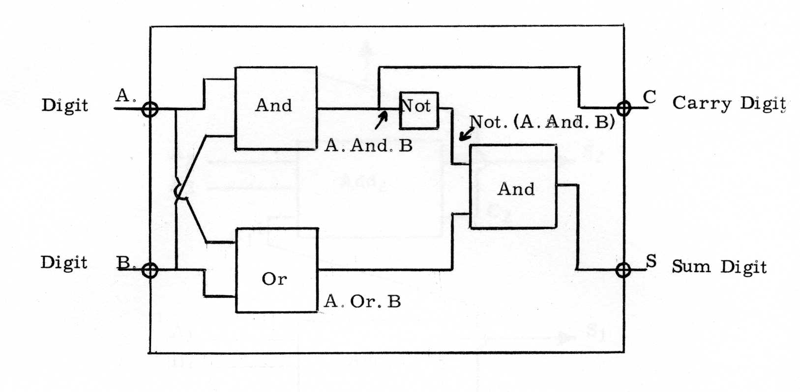
One configuration of the three basic logical components which will satisfy the laws of binary addition has been chosen, the expressions for the sum and carry may be re-arranged in a number of ways, and each different expression will represent a physically different way of constructing a half adder.
The half-adder illustrated in Fig. 1 can be engineered using either thermionic or semi-conducting components, if thermionic components are employed then eight cathodes and eight resistors and condensers would be needed, such a circuit would operate at frequencies in the region of 1Mcs/sec.
Inside the computer binary numbers of perhaps 30 or 40 digits have to be added together. The addition of each digit can be executed in parallel or serially, according to the manner in which the digits are made available from the main store and from the accumulator. One method involves the use of a separate channel or wire for each digit of the number, and all digits are transmitted simultaneously in parallel. With the other method, only one channel or wire is used and the digits are transmitted one at a time serially on this channel. For parallel operation it is necessary to provide an adder for each digit of the number, whereas for serial operation only one such device is necessary.
A serial adder is illustrated in Fig. 2., the digits A and B are added to the digit C1 which is the carry digit possibly generated during the addition of the previous two digits presented at A and B. The resulting sum digits is presented, and the carry digit C is routed back to the input of the adder via a unit which will delay the passage of the signal by exactly the correct amount, so that it will arrive coincident with the next most significant digits at A and B.
The three input adder illustrated in Fig. 2 can be fabricated from two half-adders and an Or unit as shown in Fig. 3. The first half-adder is used to sum A + B the second half-adder completes the addition
C1 + (A + B)
In Fig. 4 the arrangement of a parallel adder is illustrated. The least significant digits A1 and B1 of the two numbers are added in adder 1, and the sum digit S1 is presented, the carry digit C1 is applied as C1 1 to the carry input of adder 2. The same procedure is applied through a chain of adders equal in number to the number of digits in the numbers concerned. The actual adder circuit can again be obtained from a suitable combination of two half-adders.
The serial system is obviously the more attractive from a cost and maintenance viewpoint, whereas the parallel system is obviously much faster.
A floating point adder is designed to operate on numbers of the form a2b where a may be a 30 digit binary fraction and b a 10 digit binary integer. The actual arithmetic has to be conducted in a series of stages; first the exponents b1 and b2 of the two numbers being added are compared, and the numbers a1 and a2 are adjusted either in time or by the position of their digit channels, so that the corresponding digits of each number are correctly aligned. The numbers are then added to form a quantity a3 1 , this number is adjusted to satisfy the standard requirements of a floating point number and its associated exponent b3 is computed separately. In view of the extra complexity, a floating point adder is the more difficult to design and construct, but it can be expected to operate much more efficiently than any programmed method for performing the same operations with a conventional adder.
An adder can most easily fulfill the requirements of a subtractor by changing the sign of the appropriate input quantity e.g. if we wish to subtract 5 from 6 then we add -5 to 6. An adder is therefore conveniently converted into a subtractor by providing an extra unit to alter the sign of one of the input numbers. The nature of the converter will depend upon the method adopted for representing a negative number but even in the most unfavourable conditions the equipment should not exceed that of a half-adder.
We have described how an adder is built of a number of logical units which between them simulate the rules of binary arithmetic, if the operation of certain of these units is inhibited then the effective action of the adder can be altered. By simply inhibiting certain channels within a logical adder the operations And and Not Equivalence can be simulated.
Multiplication by the paper and pencil method using the decimal system is accomplished with the aid of a multiplication table, which is usually memorised. Multiplication in the binary system may be accomplished in the same way, although the binary multiplication table is so simple that it is almost trivial. It is shown in Table 3.
Binary Multiplication Table

                    0  1   Multiplicand digit
Multiplier Digit 0  0  0
                 1  0  1
In the conduct of a multiplication the formation of each partial product merely involves extracting a copy of the multiplicand, if the multiplier digit is 1 then the partial product is equal to the multiplicand, and if the multiplier digit is 0 then the partial product is 0. e. g.
Multiplicand    (x)       1111
Multiplier (y)            1101

Partial        (  A       1111
Products       (  B      0000
               (  C     1111
               (  D    1111
Product               11000011
The provision of equipment for the multiplication of two numbers within a computer therefore resolves itself into the problem of adding a number of partial products. The nature of this equipment is largely determined by the speed at which it is required to operate. In the example given above any number of adders between 1 and 12 could have been used and the speed would have varied by a corresponding factor of 12. In practice numbers contain between 30 and 40 binary digits and the upper limit on the possible size of the multiplier is much higher (i.e. 870 and 1560 adders).
A compromise is usually reached by providing an adder for each digit in the multiplicand (i.e. 30 or 40), and then operating on each digit in the multiplier in a serial manner. This type of multiplier arrangement is termed serial-parallel and provides the fastest type of multiplier in common use. A straightforward serial arrangement using only one adder treats both the multiplicand and the multiplier in serial form, this constitutes the slow multiplier.
The final product of a multiplication will contain as many digits as the multiplier and multiplicand combined, e.g. 60 digits if two 30 digit numbers have been multiplied. Provision is usually made for extracting either the 30 most or the 30 least significant digits of a product for further operations in the accumulator, whose other facilities are all confined to 30 digit numbers.
To obtain a quotient from a binary division, successive subtractions of the divisor must be made, from the dividend. Each time the subtraction leaves a positive remainder, a 1 is added to the corresponding order of the quotient. Each time a negative remainder results, steps are taken which nullify the subtraction and leave the quotient unchanged. The speed of a division is again governed by the number of subtractors available and a similar compromise to that reached with the multiplier is usually employed.
The remainder is normally discarded, in the few cases where it is required, it can be reconstructed by subtracting from the dividend the product of the unrounded quotient and the divisor.
