Harwell/RHEL Proton Linear Accelerator (PLA) photograph albums
Installation in Building 412 (1956-1957)
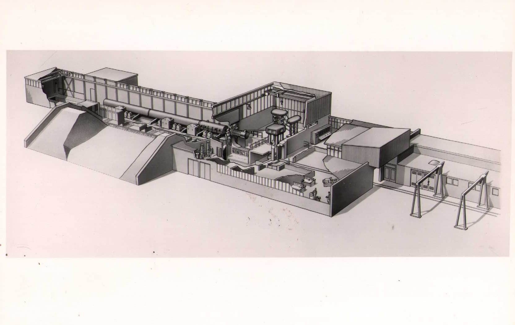
The PLA was originally installed by Harwell in Building 412. It was later handed-over to RHEL when the building became known as R12.
This photograph album has suffered extensive water damage.
Photograph album cover
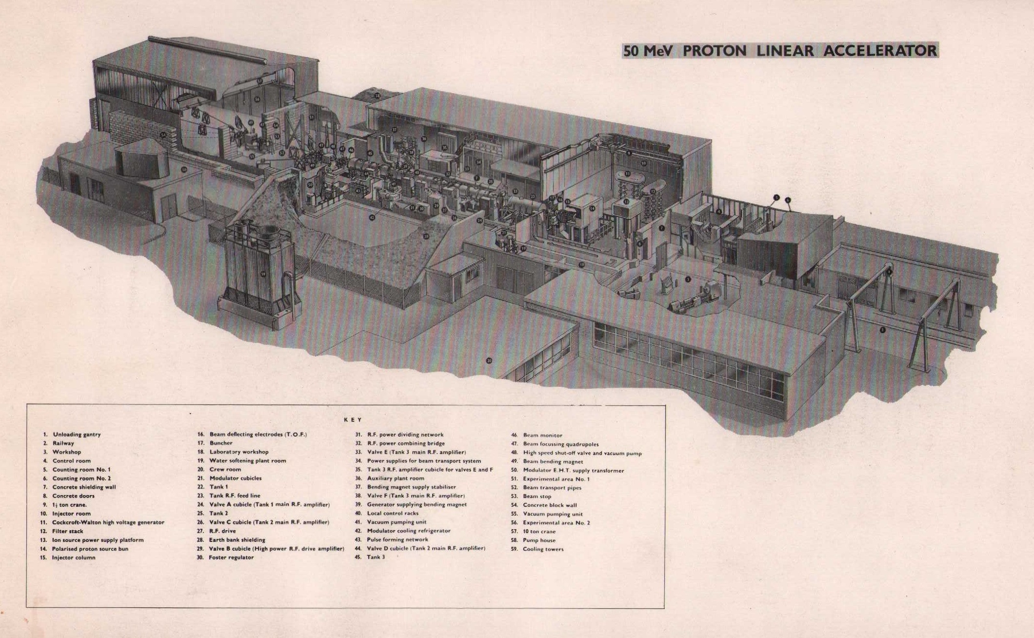
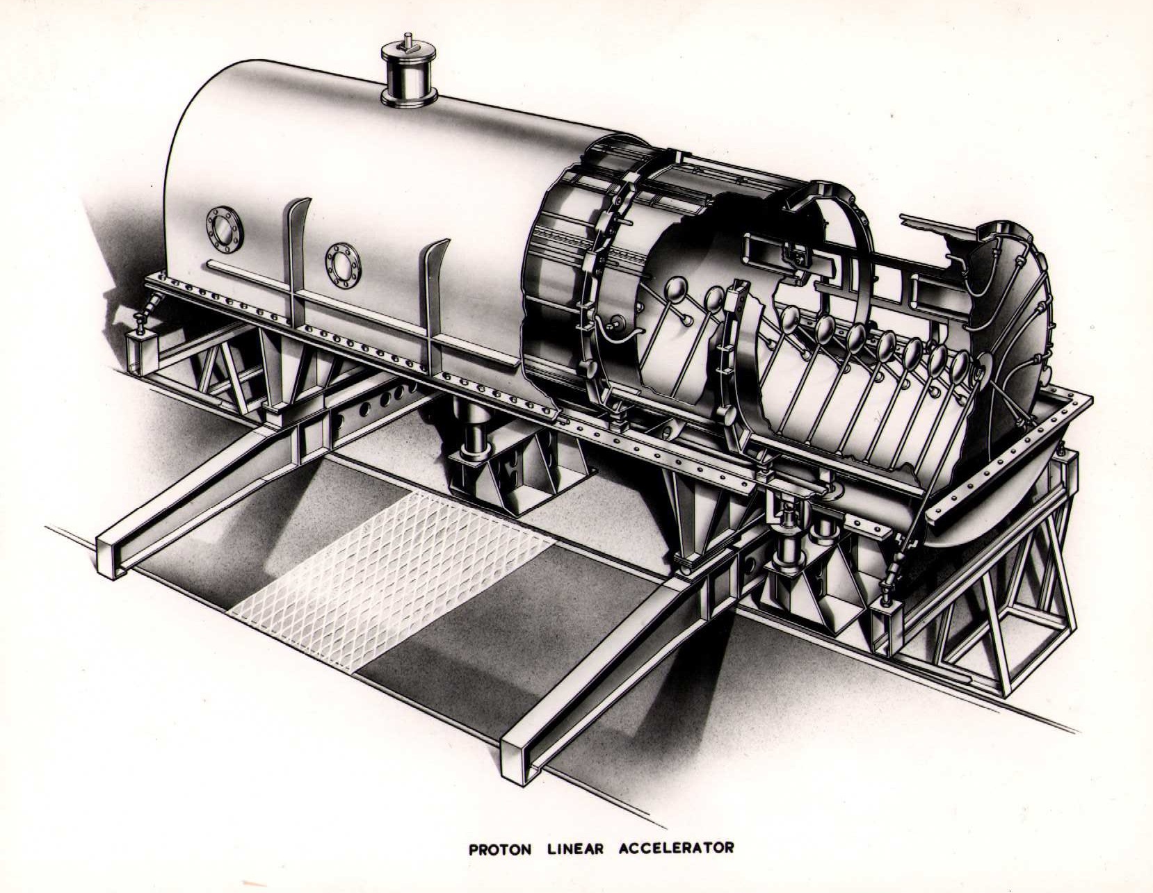
Cut-away drawing of the 50 MeV Proton Linear Accelerator
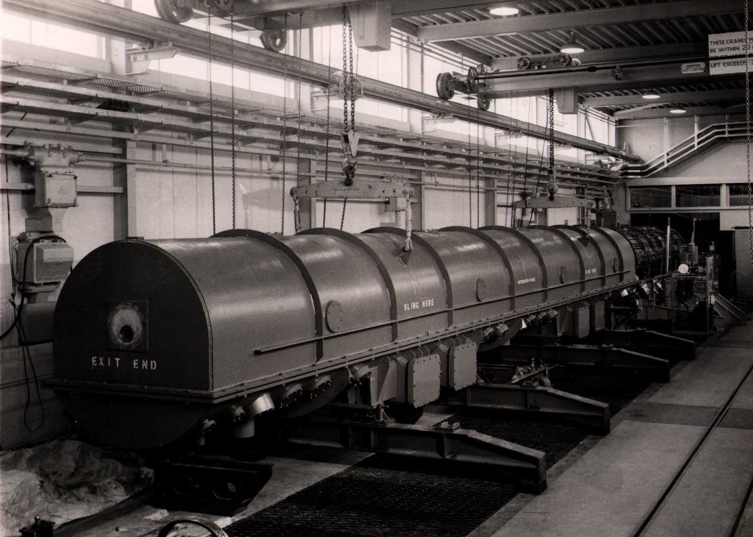
16 May 1956: Tank 1 liner in vacuum envelope from input end
16 May 1956: Tank 1 liner in vacuum envelope from output end
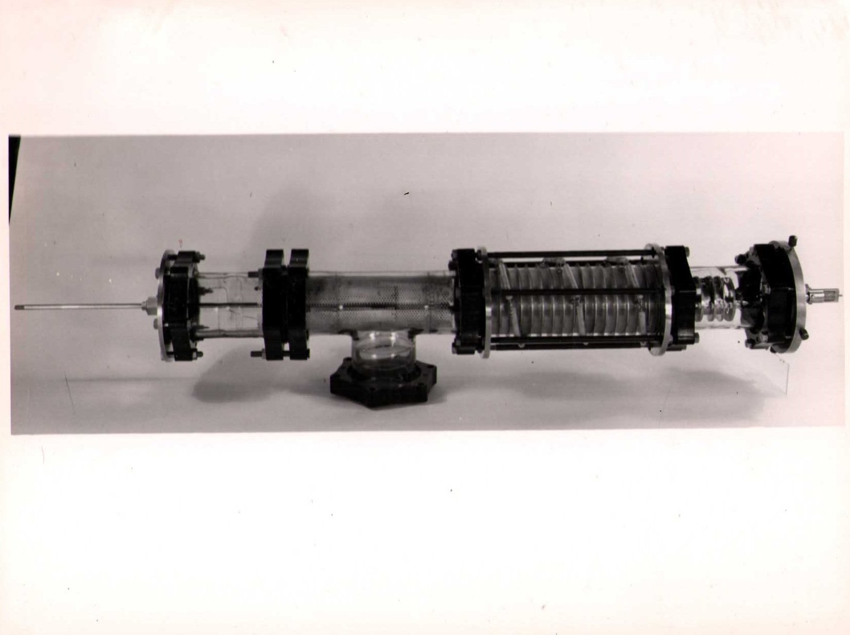
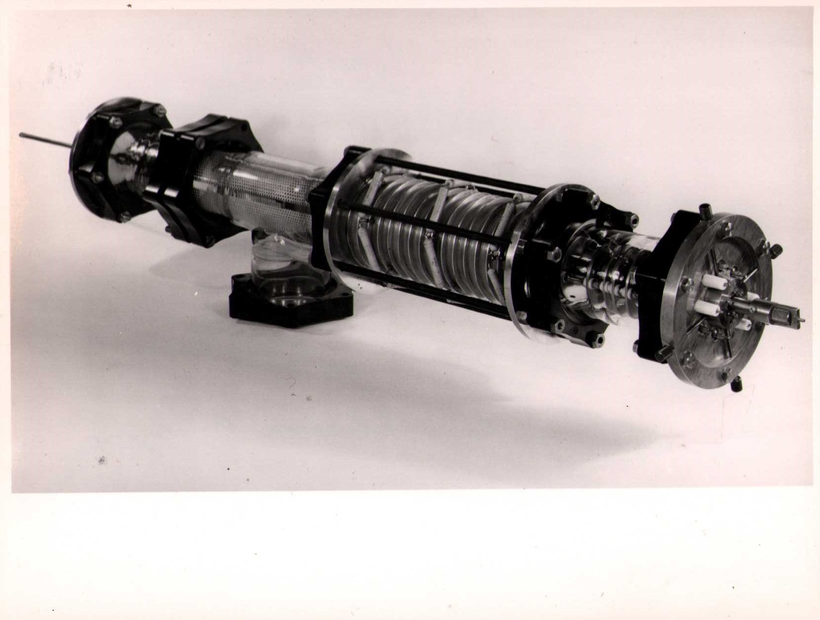
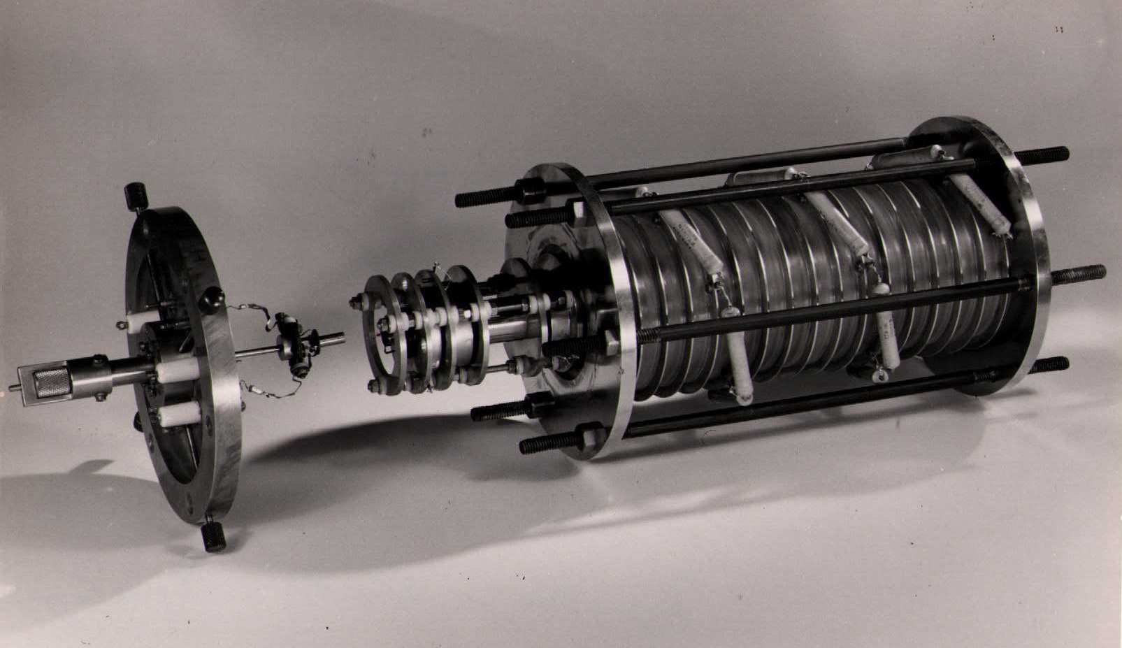
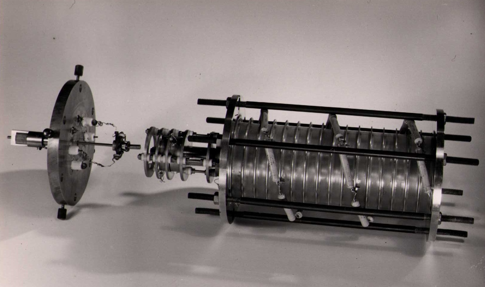
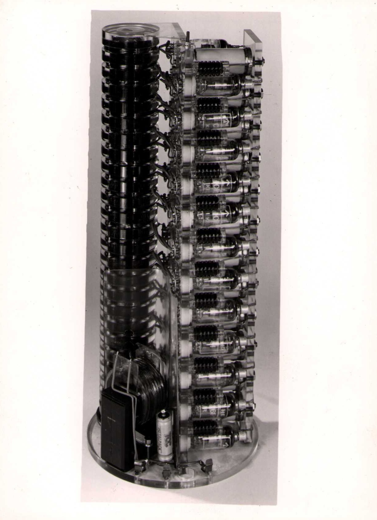
Injector - Electron analogue
Injector - Electron analogue
Injector - Electron analogue
Injector - Electron analogue
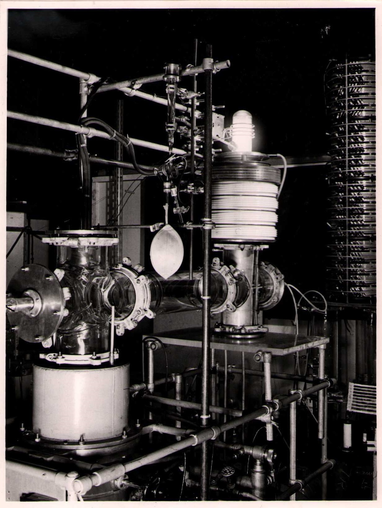
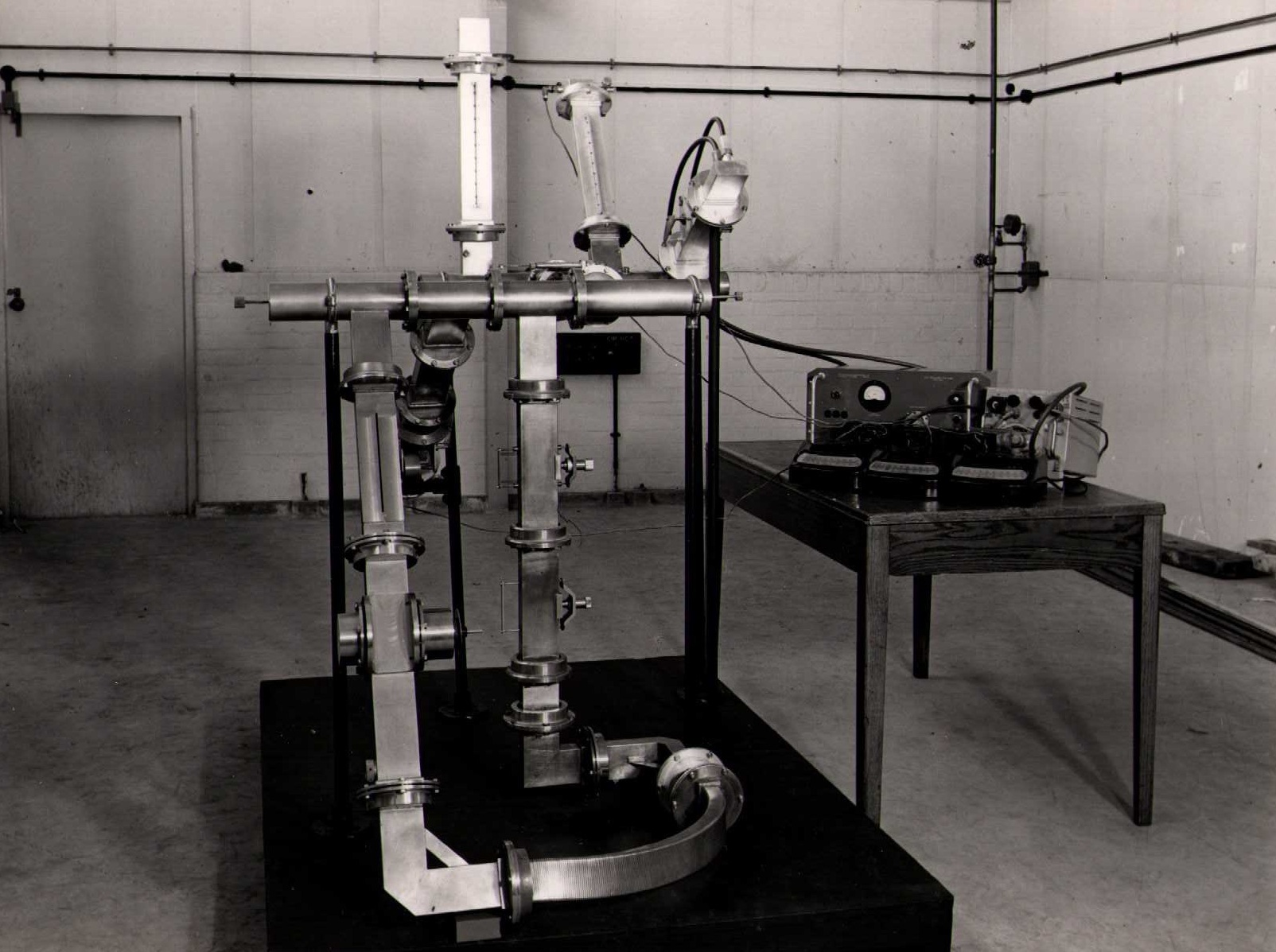
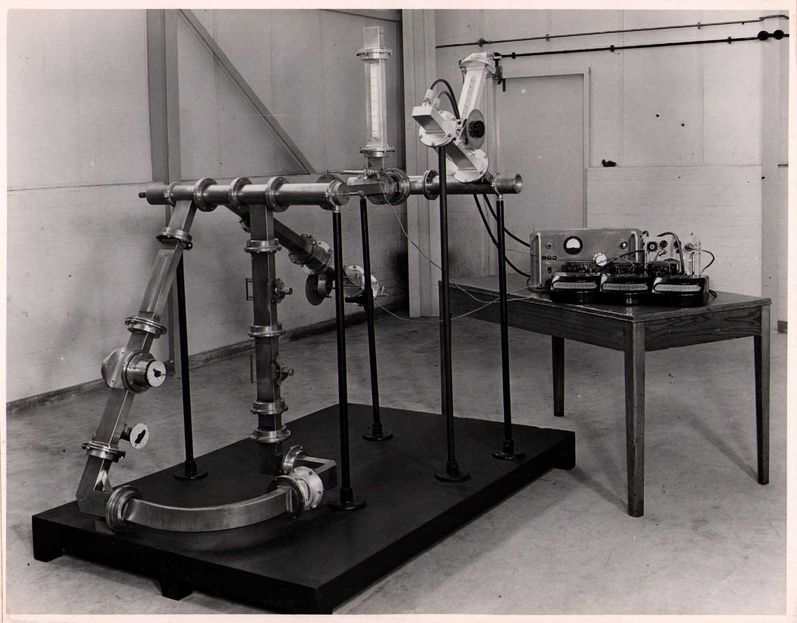
Experimental apparatus for ion sources and beam focusing
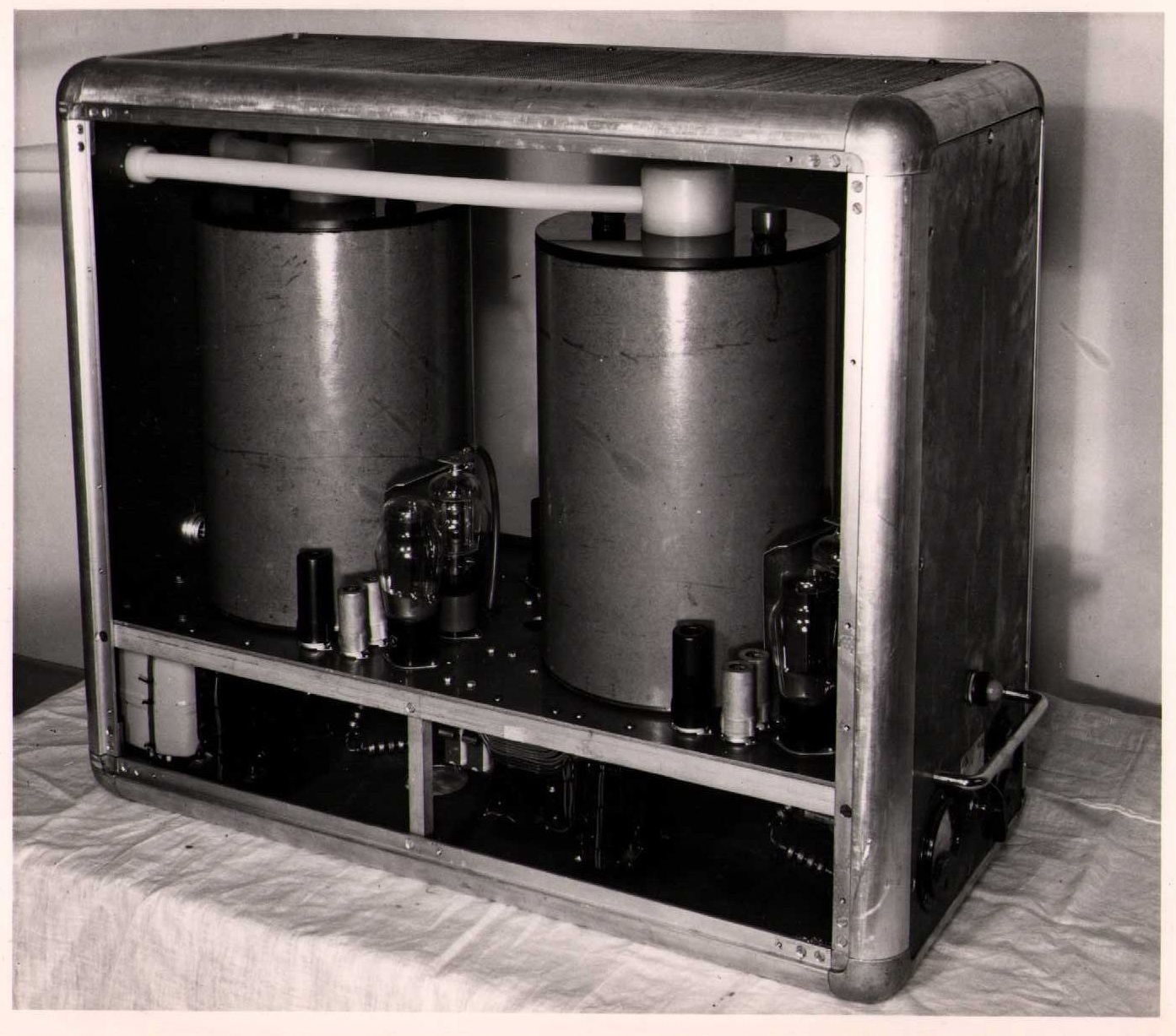
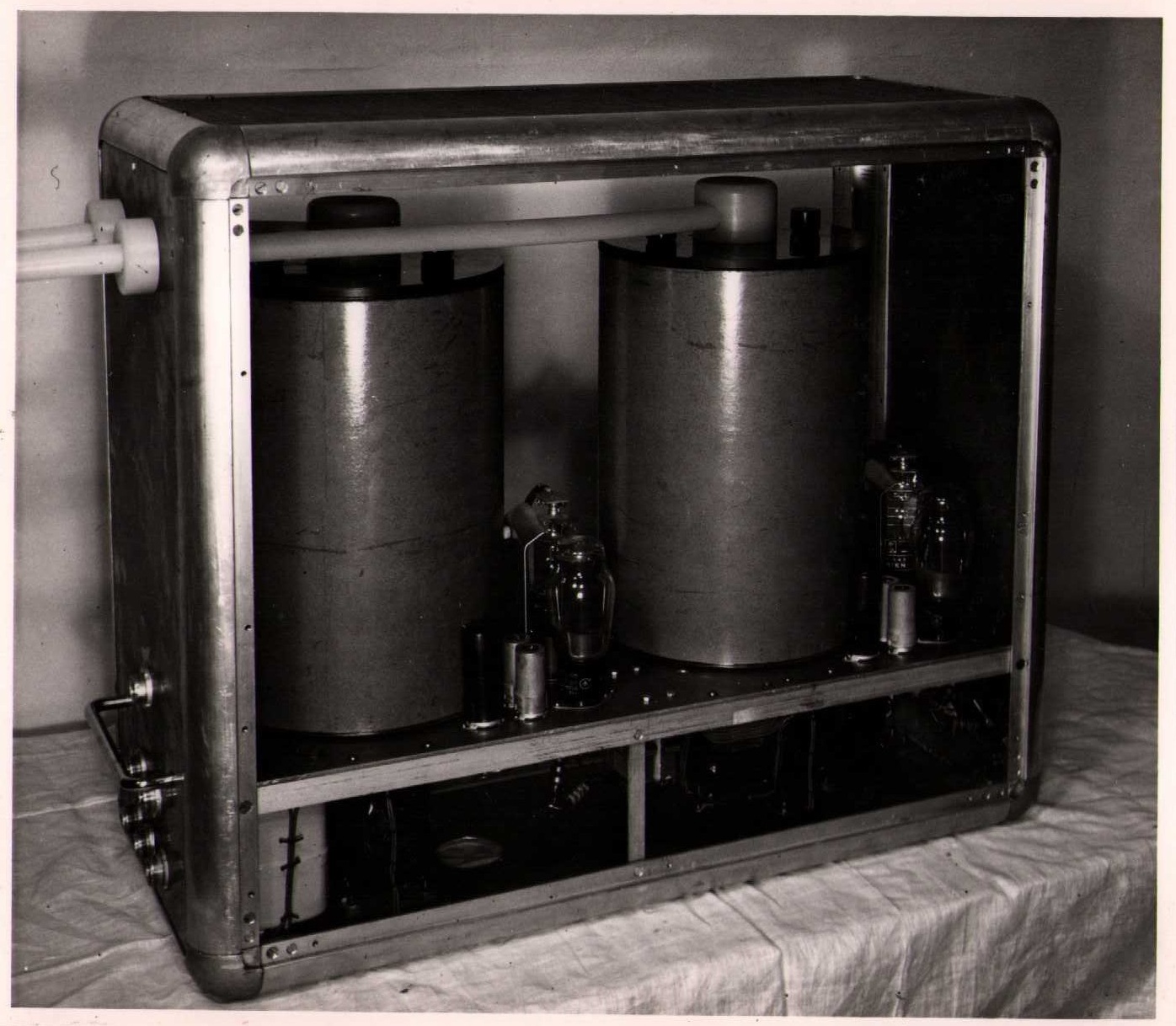
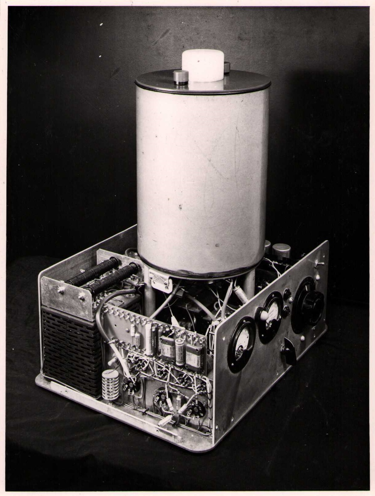
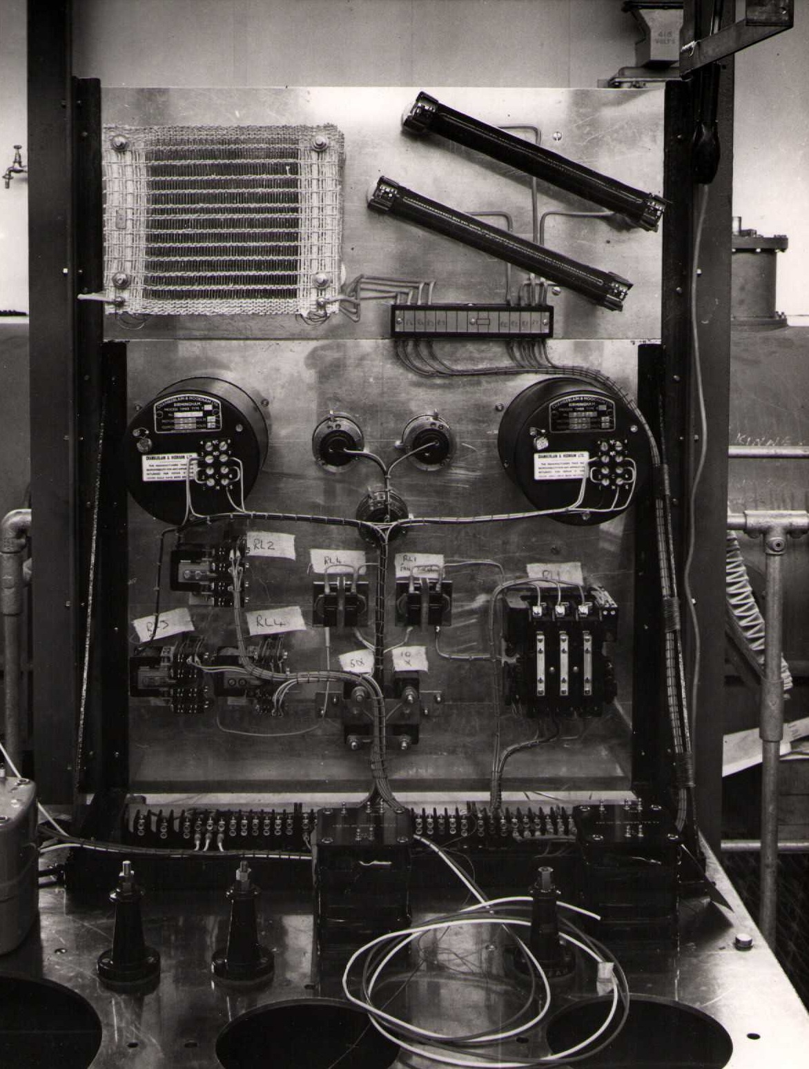
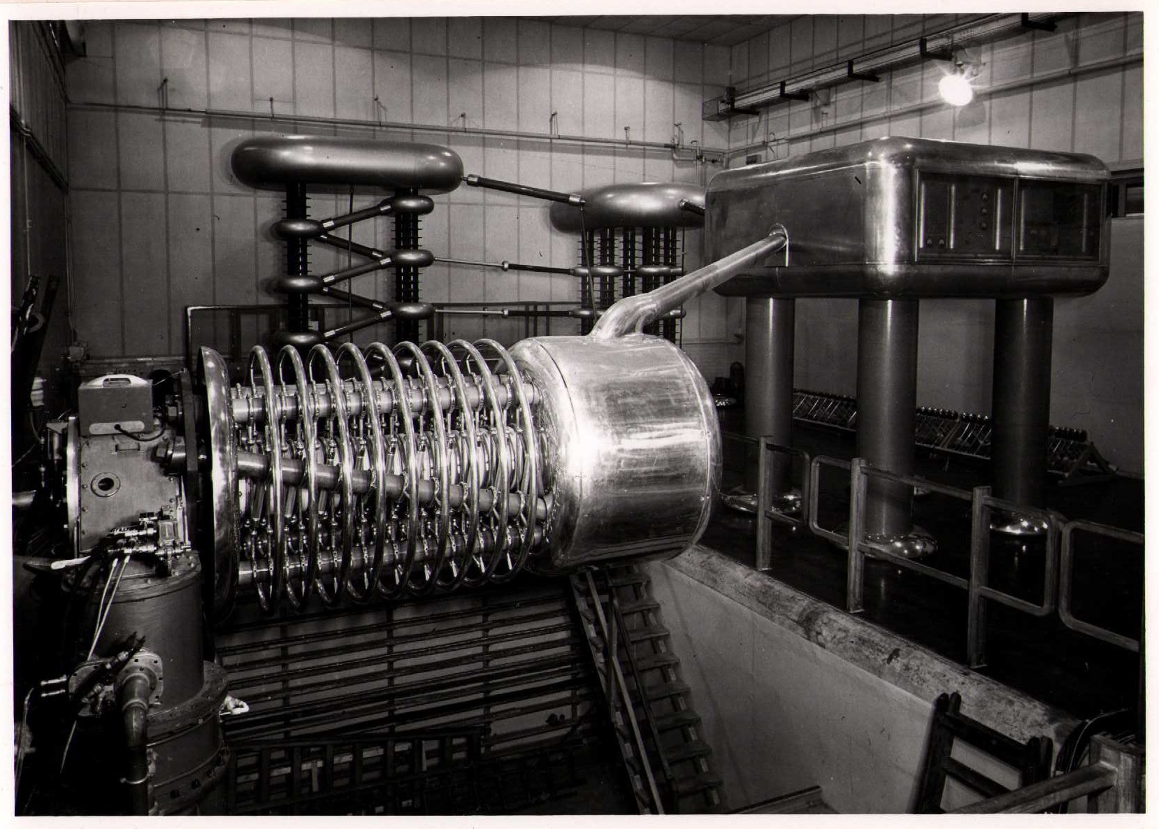
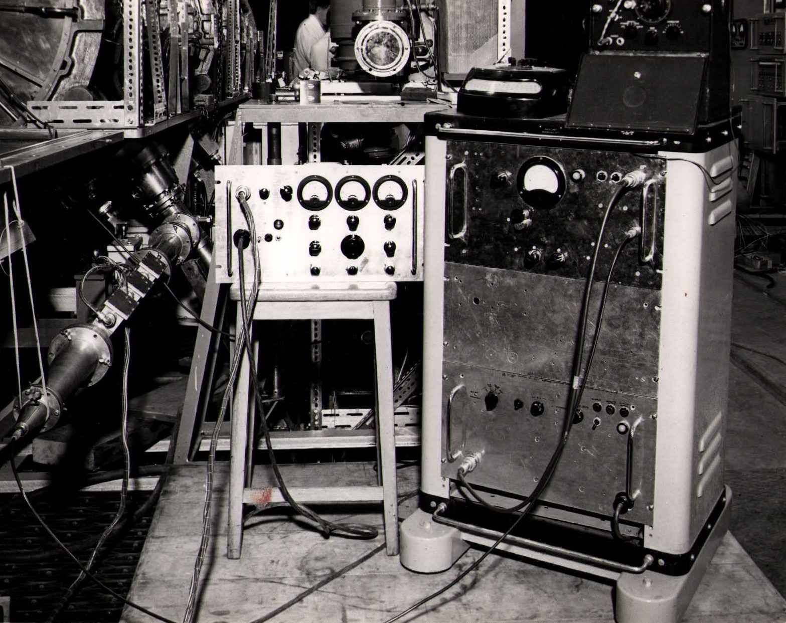
View (1) A high voltage DC supply unit for the injector focusing electrodes
View (2) A high voltage DC supply unit for the injector focusing electrodes
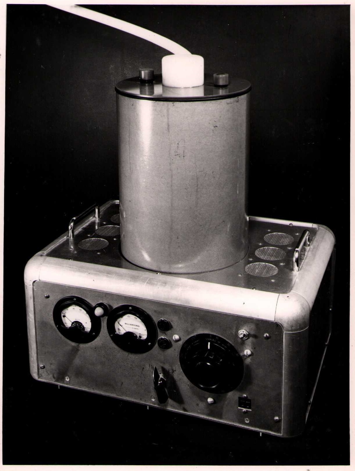
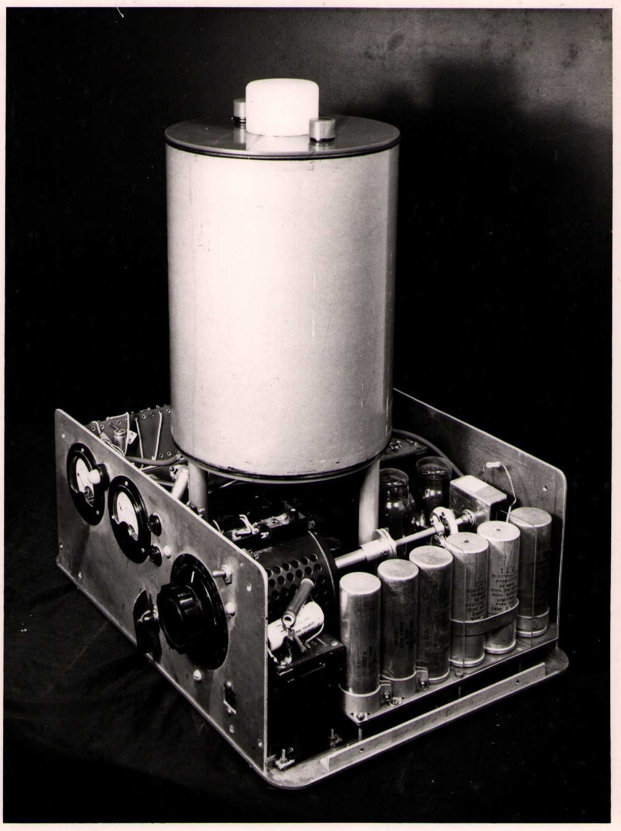
View (1) A prototype high voltage unit for laboratory use
View (2) A prototype high voltage unit for laboratory use
View (3) A prototype high voltage unit for laboratory use
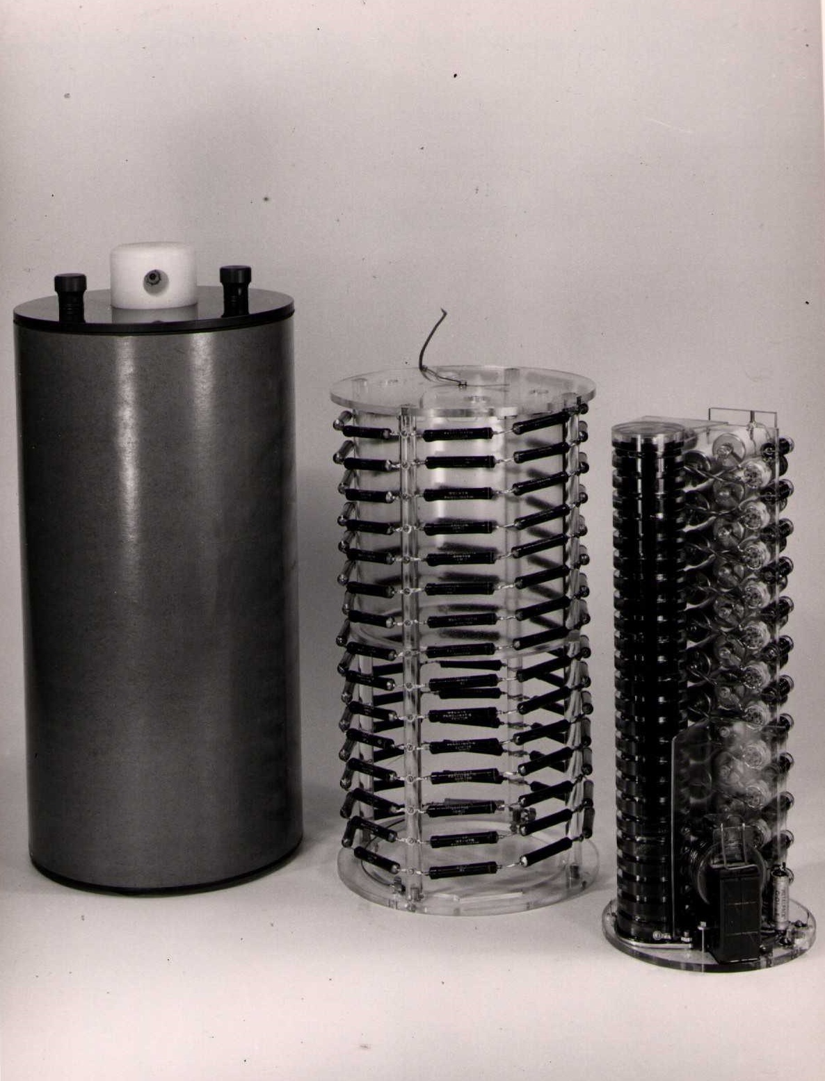
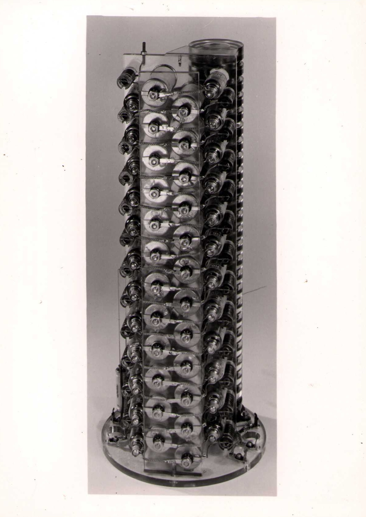
The components of a 120 KV voltage multiplier
The components of a 120 KV voltage multiplier as removed from their oil-filled container
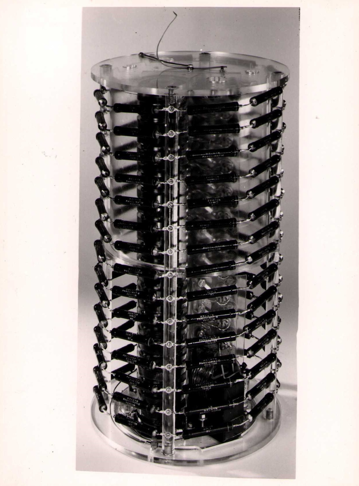
View (1) The voltage-multiplier stack for a 120 KV supply
View (2) The voltage-multiplier stack for a 120 KV supply
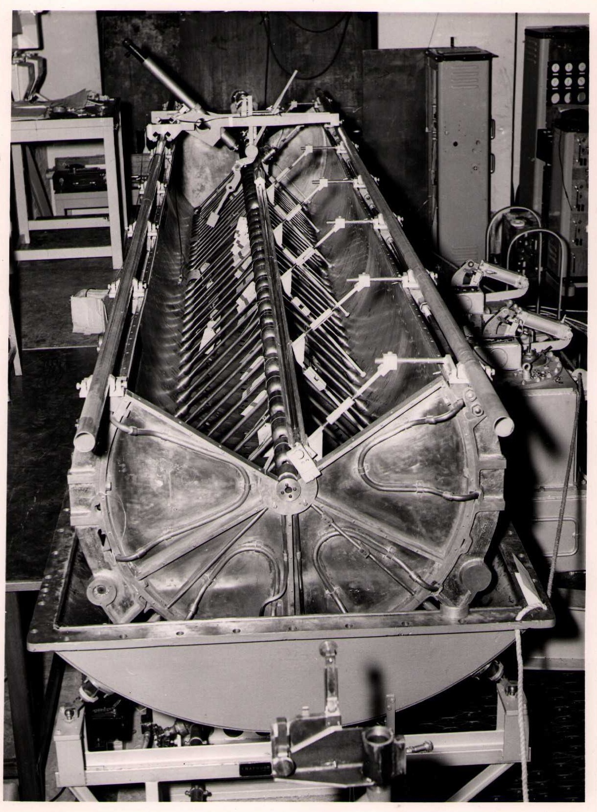
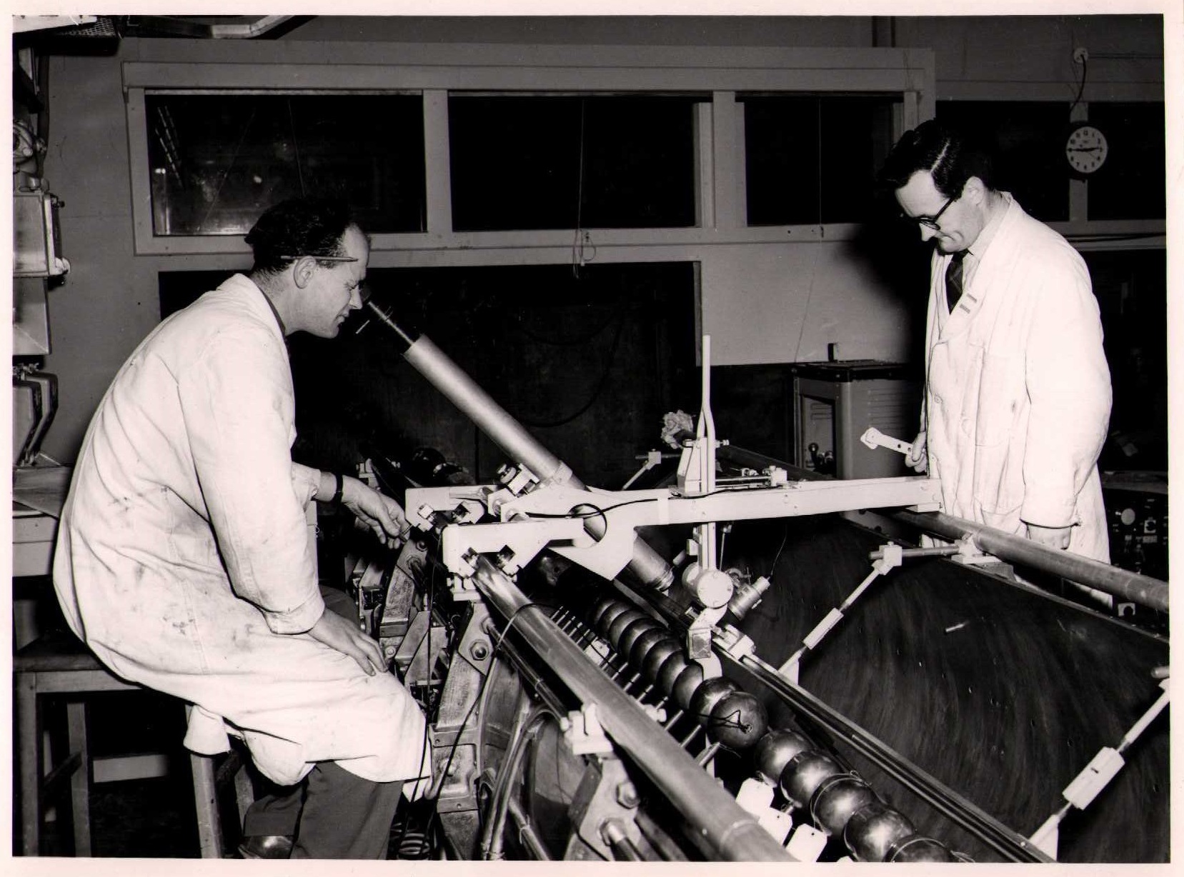
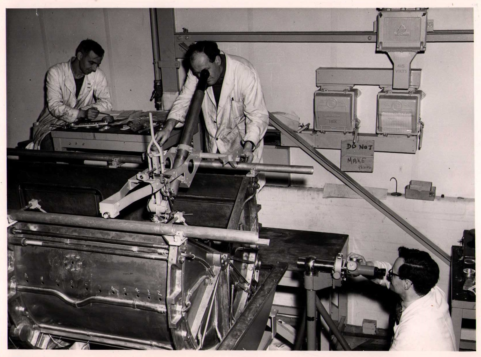
1 October 1956: Tank 1 showing position measuring telescope gauge bars and rails on liner
1 October 1956: Optical equipment for alignment and positioning of drift tubes in Tank 1
1 October 1956: Optical alignment and positioning of drift tubes in Tank 1
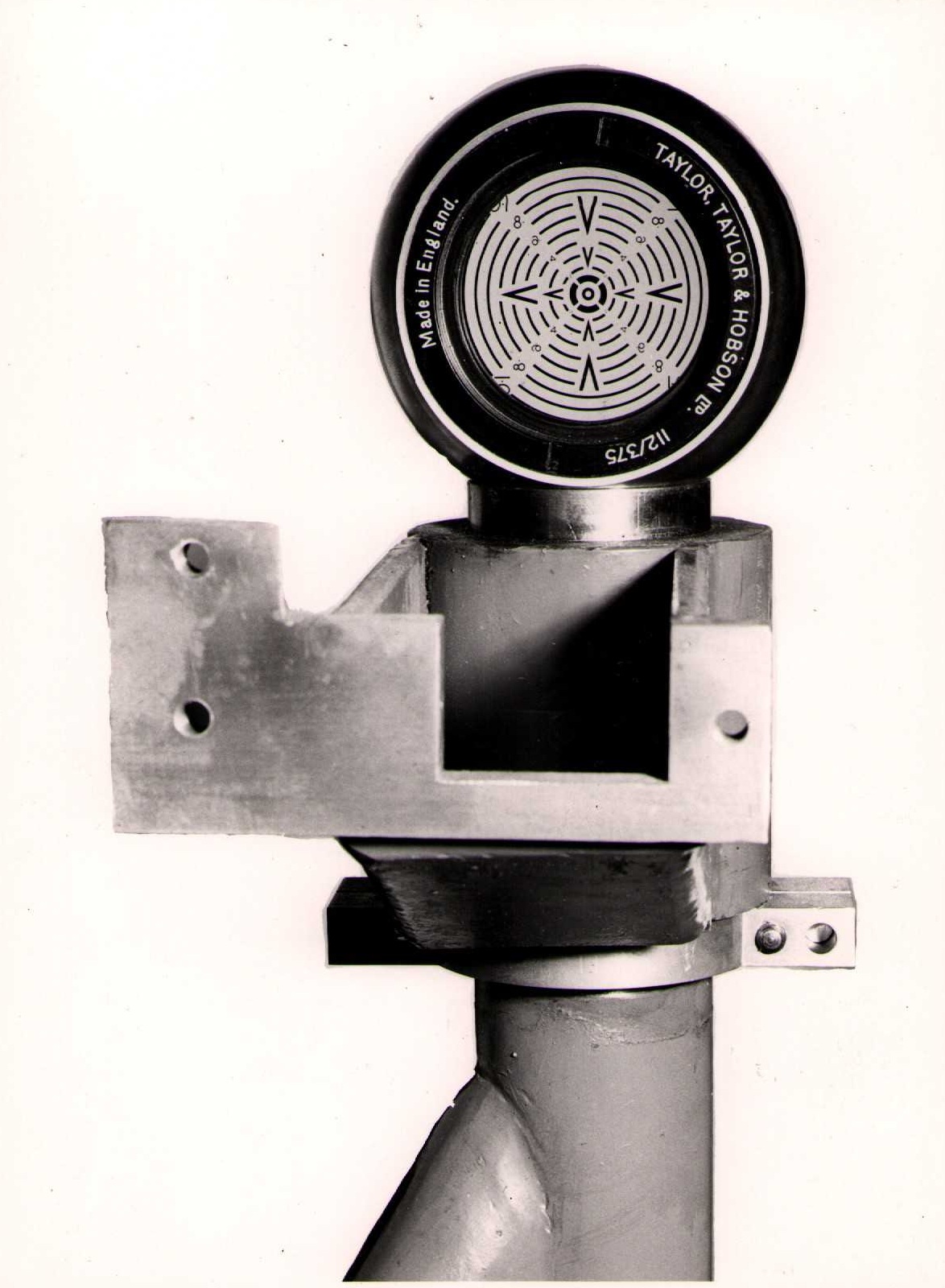
1 October 1956: Optical alignment target in position on supporting stand
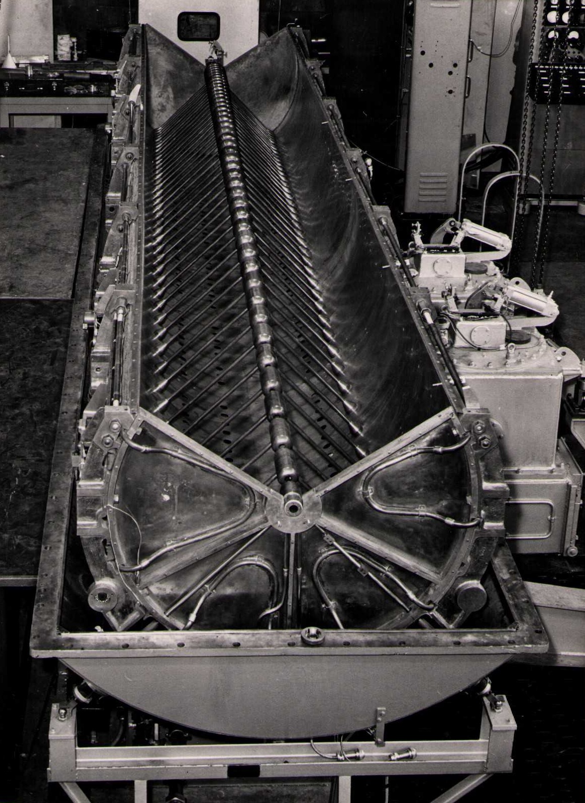
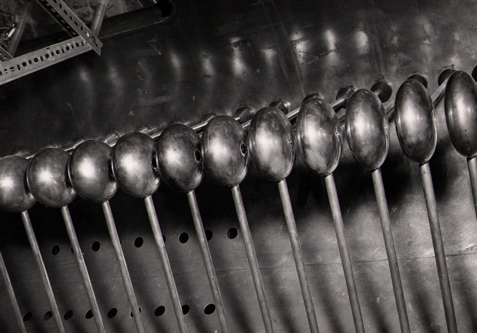
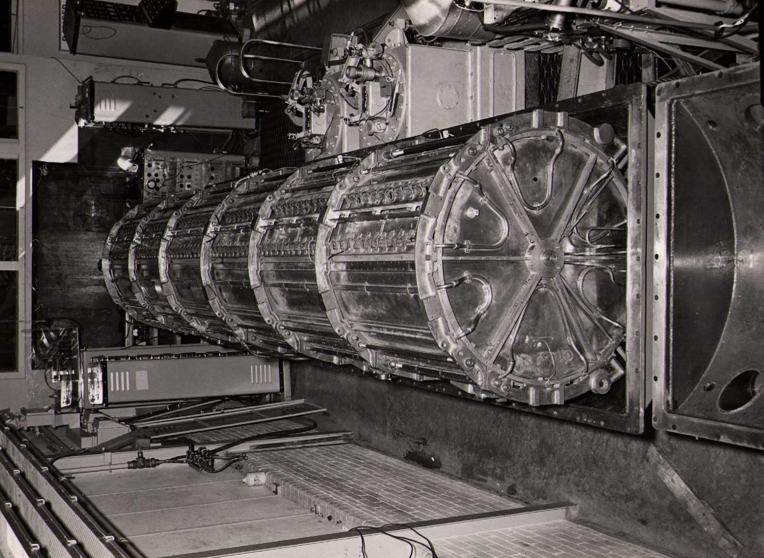
11 October 1956: Tank 1 liner with lid removed to show drift tubes (view from output end)
11 October 1956: Tank 1 liner in position in lower half of vacuum envelope
11 October 1956: Tank 1 with liner lid raised
Model of the PLA building
Proton Linear Accelerator (drawing)
Early 1956: Heater controls for part of drive chain
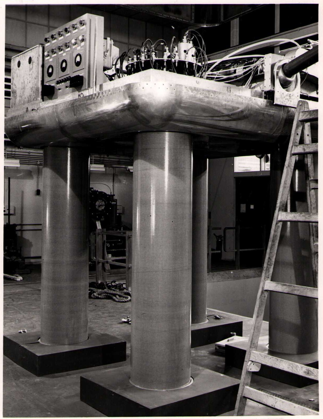
Early 1956: High voltage platform
Early 1956: Part of high voltage platform showing remote control column
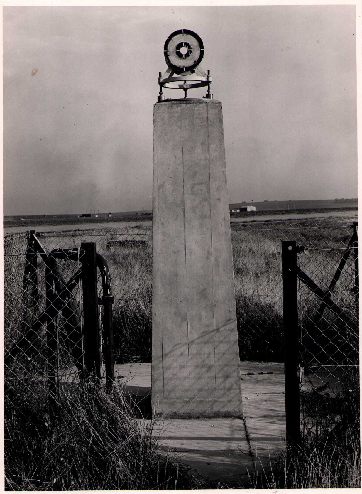
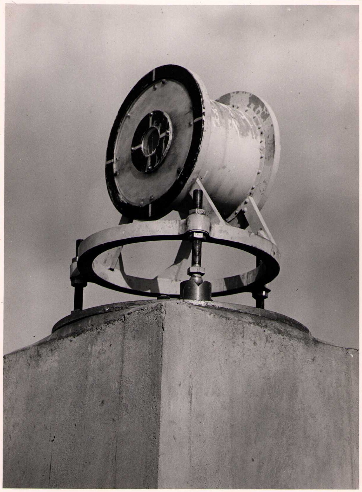
30 October 1956: Distant lighting target on plinth
30 October 1956: Distant lighting target
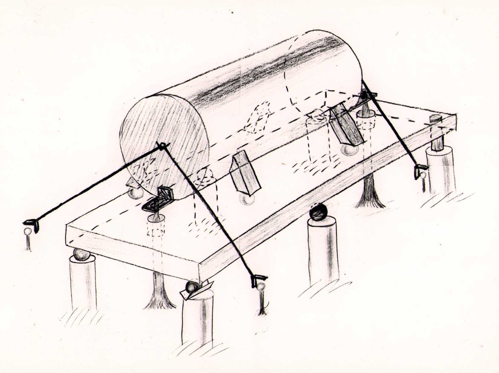
Drawing of Tank
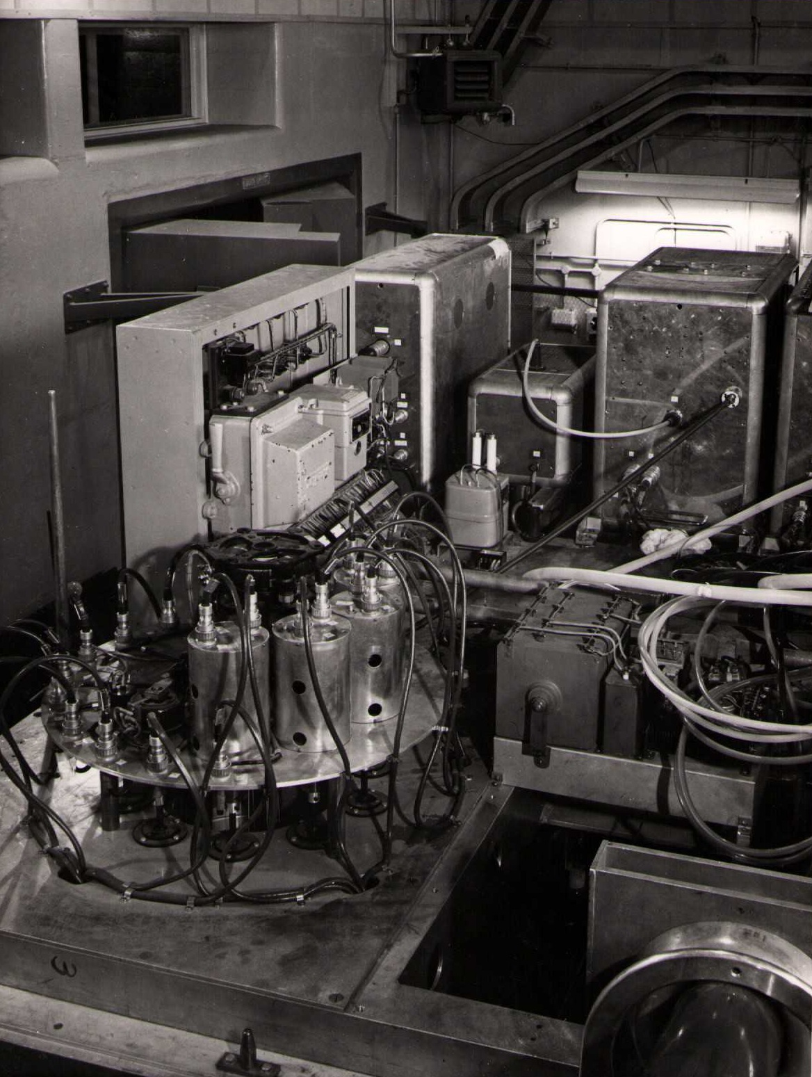
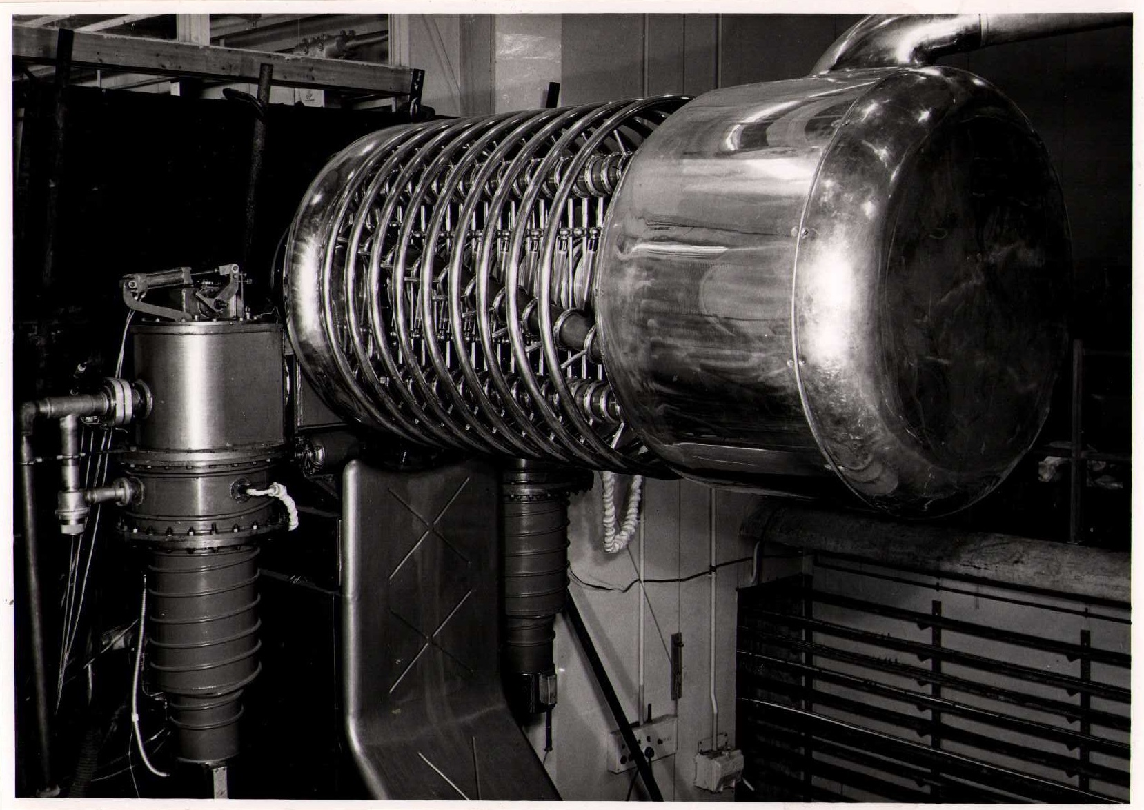
22 November 1956: General view of injector room
22 November 1956: Injector
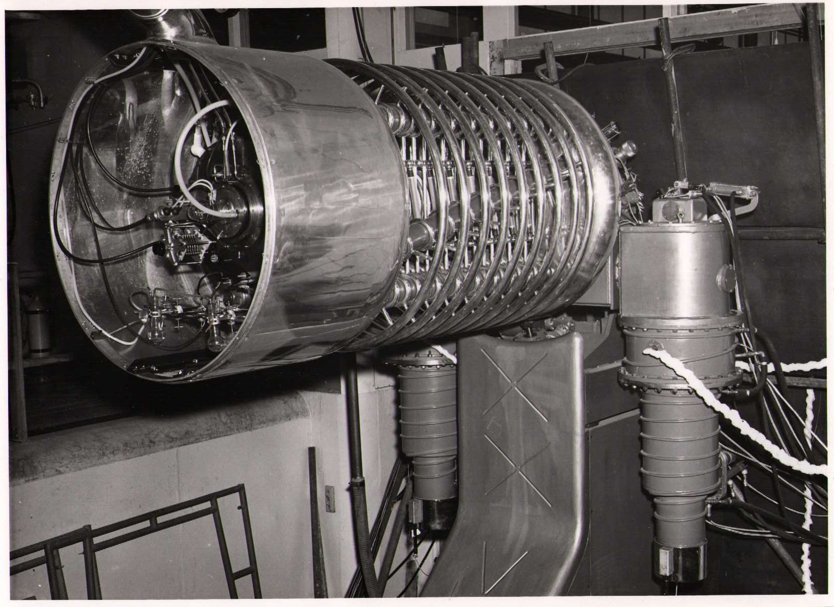
22 November 1956: Injector with ion sources cover removed
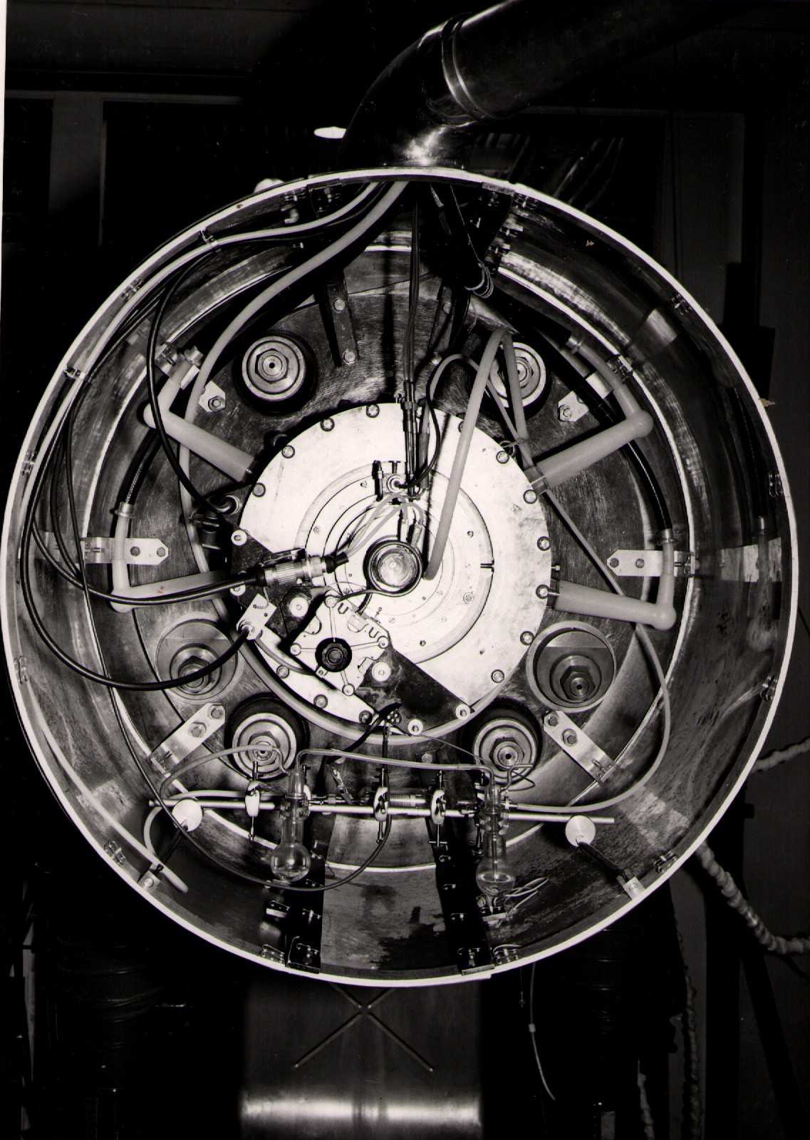
22 November 1956: Injector -- end view with cover removed showing ion sources
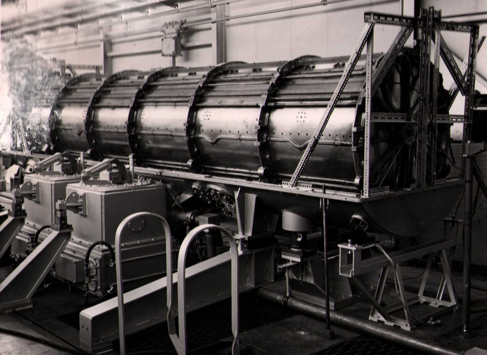
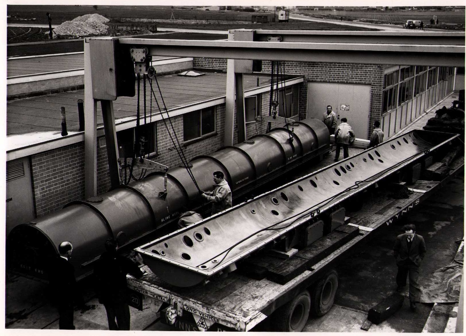
9 January 1957: Tank 2 vacuum envelope arriving at Building 412
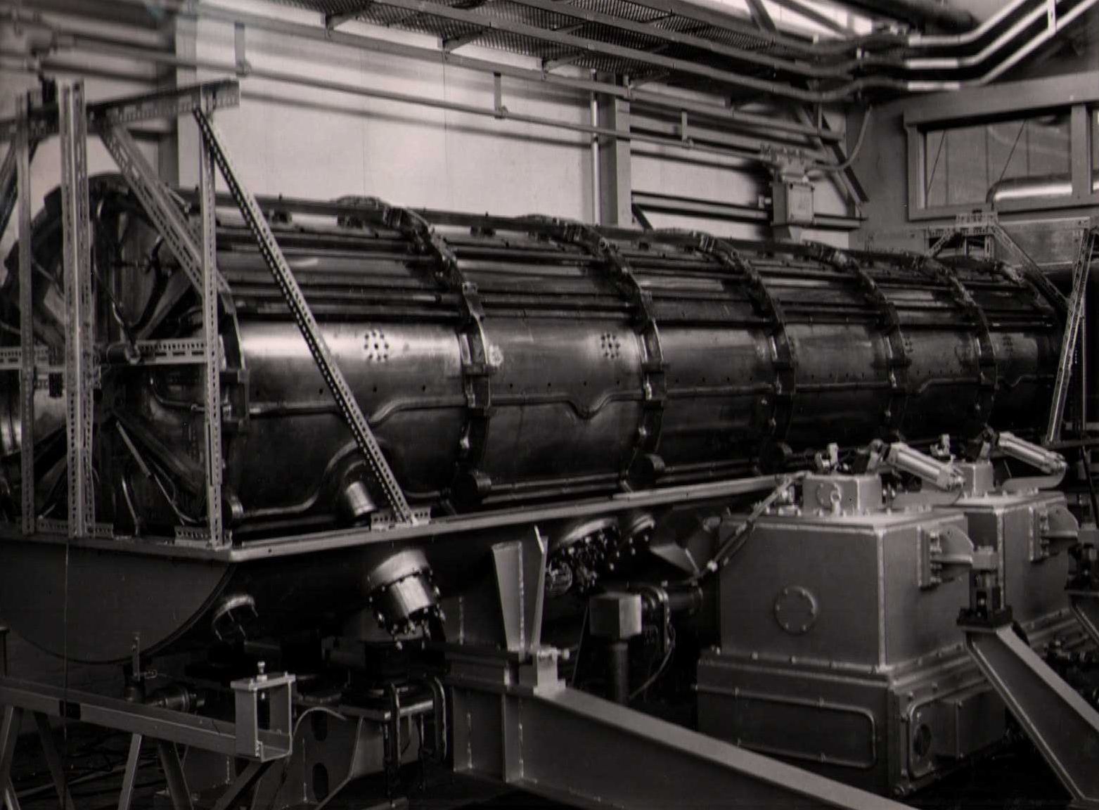
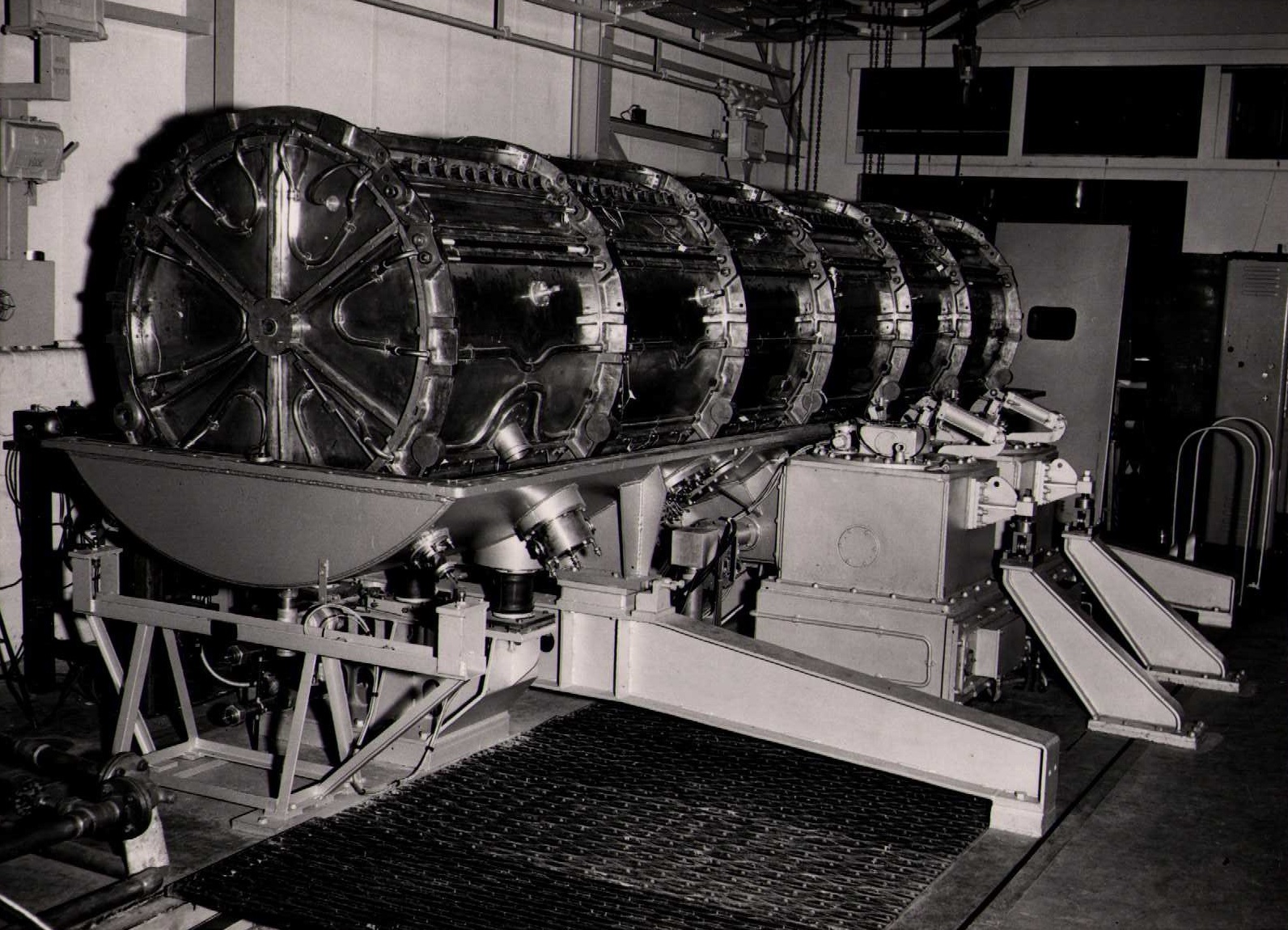
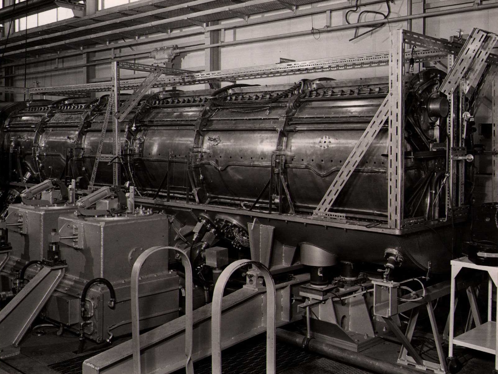
14 January 1957: General view of Tanks 1 and 2
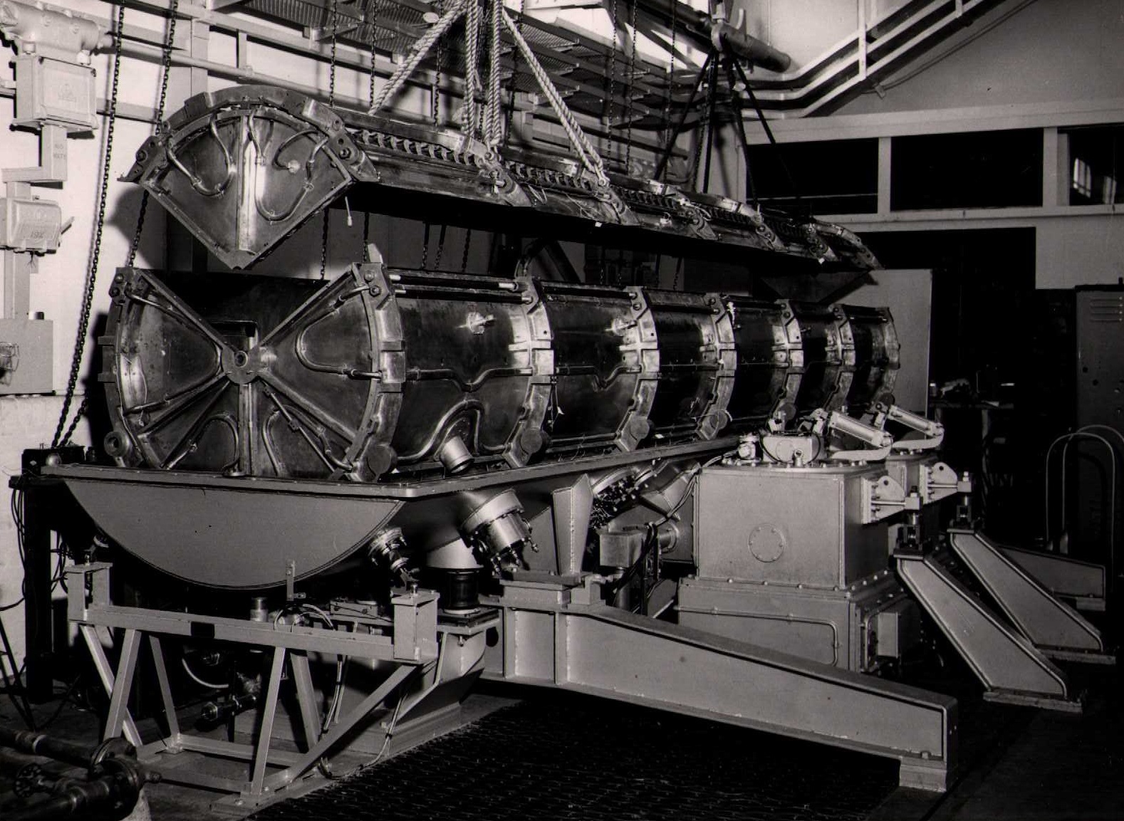
14 January 1957: Tank 2 vacuum envelope in position
1956: 10cm model accelerator feedback system
1956: 10cm model accelerator feedback system
29 January 1957: Tank 1 lined with framework for supporting perturbation measurement for string and bead
29 January 1957: Perturbation measurement field plotting on Tank 1 liner
29 January 1957: Perturbation measurement equipment for field plotting in Tank 1 liner
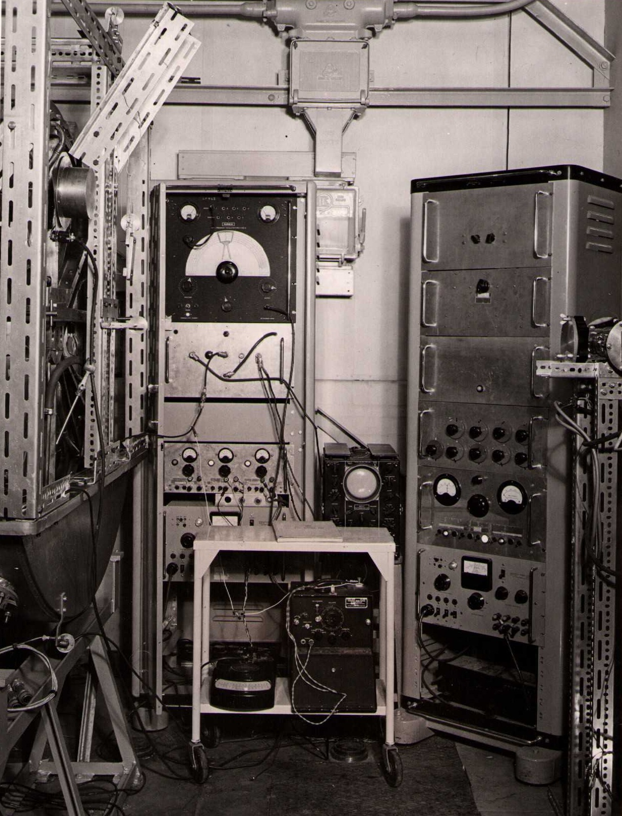
February 1957: Three probe liner impedance measuring equipment on feed to Tank 1 liner
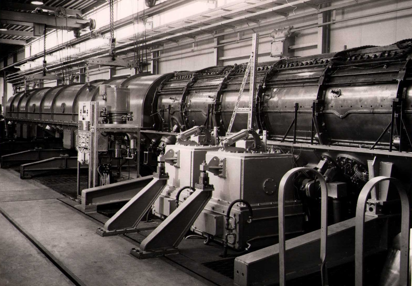
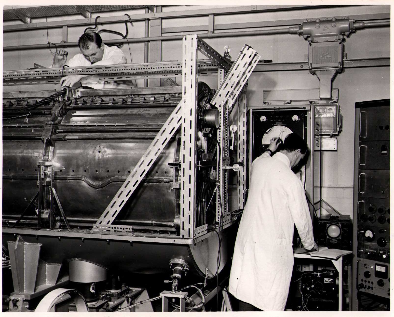
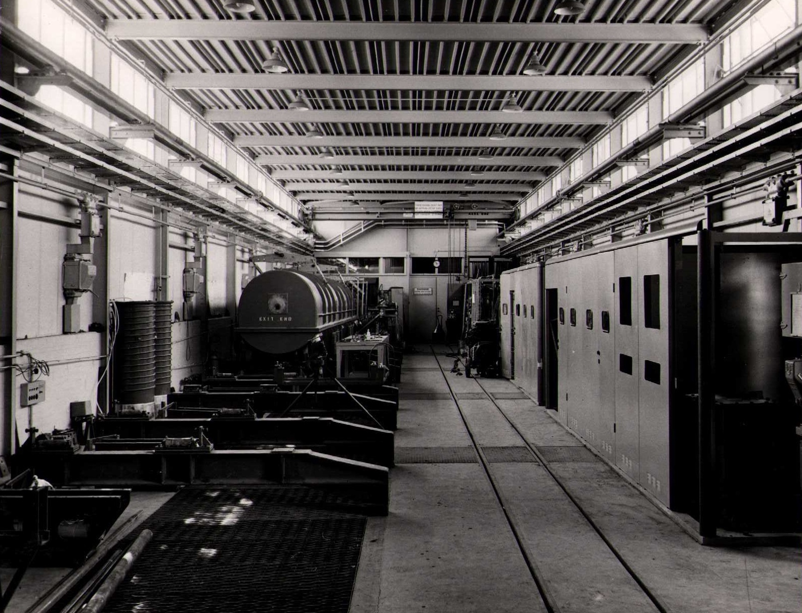
March 1957: General view of tunnel showing progress on Tank 2 and modulators
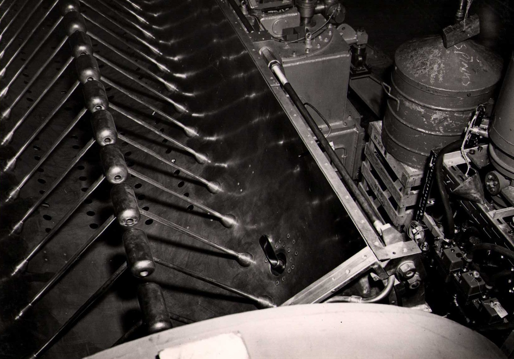
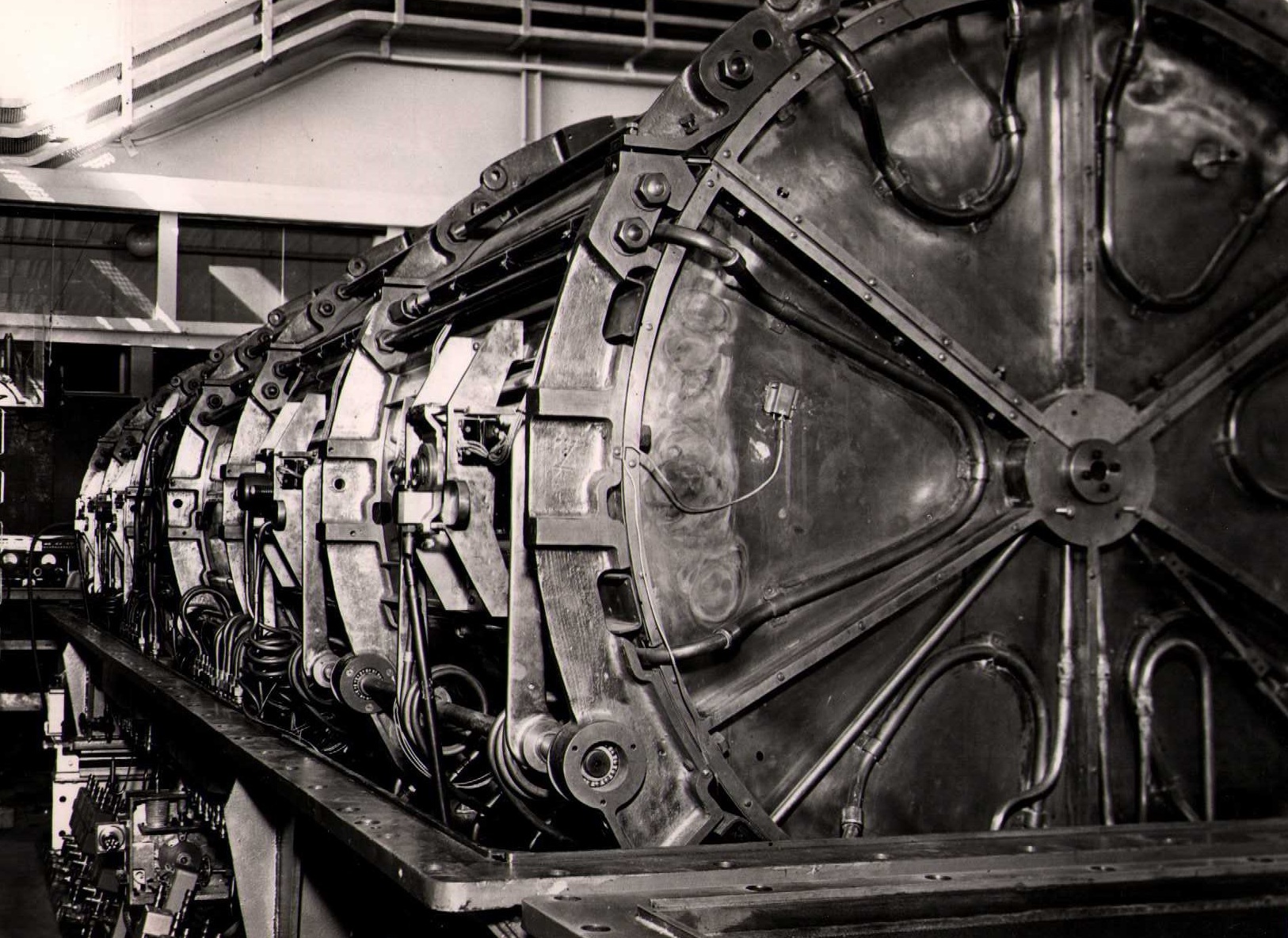
15 April 1957: Tank 1 drift tubes near input end showing grids
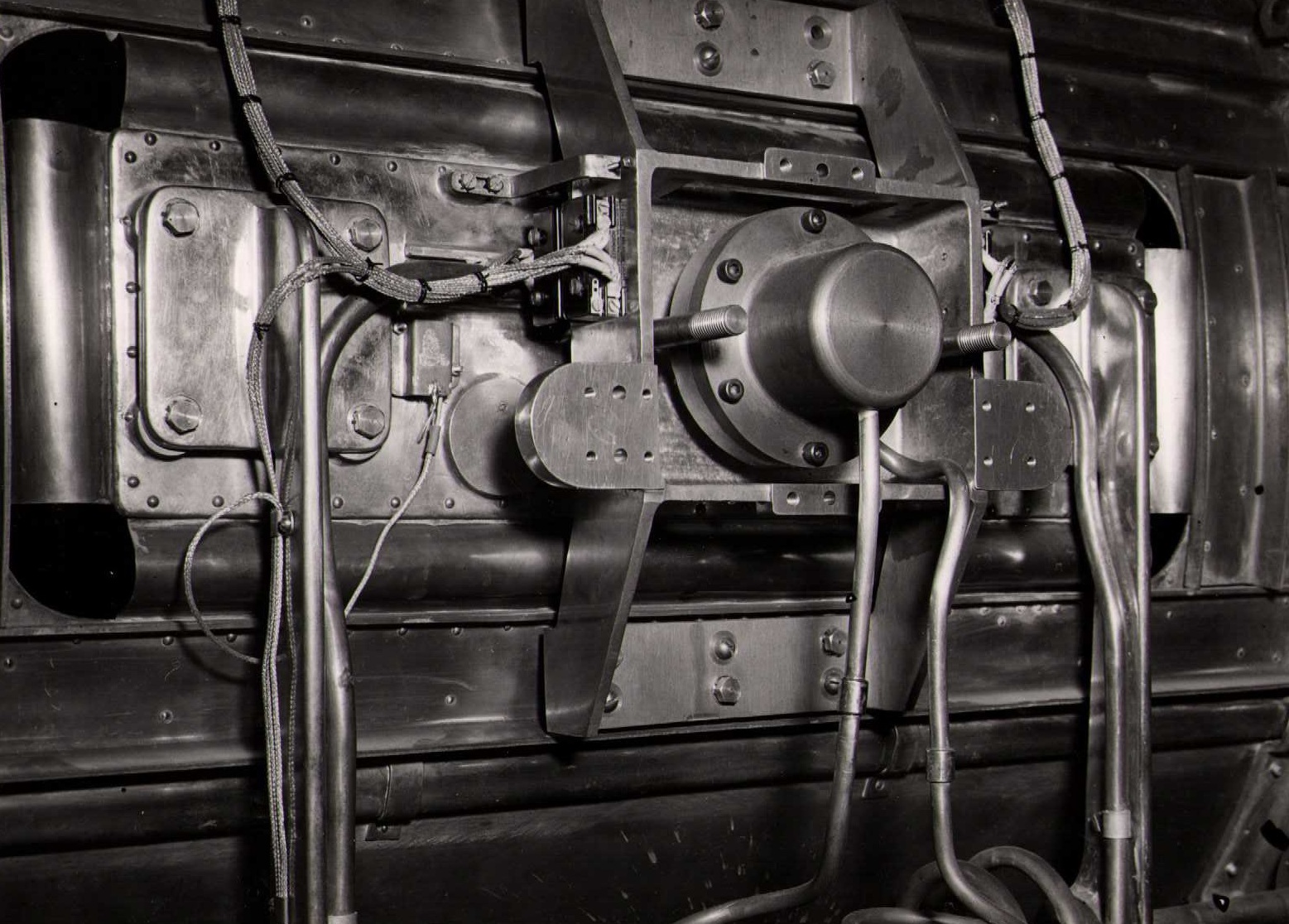
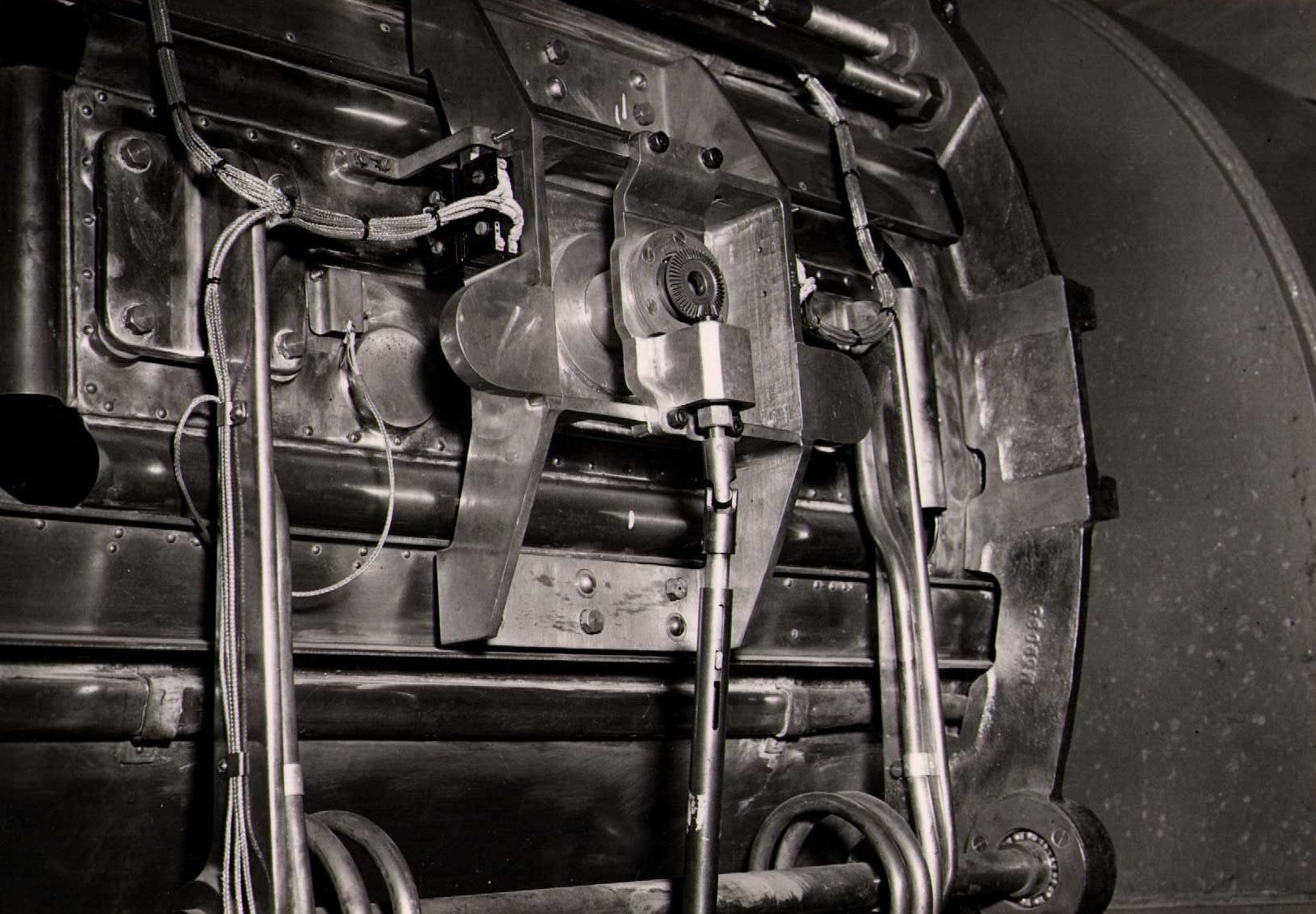
15 April 1957: Tank 1 frequency tuner -- external view
15 April 1957: Tank 1 liner with lid removed showing drift tubes near output end and RF feed loop
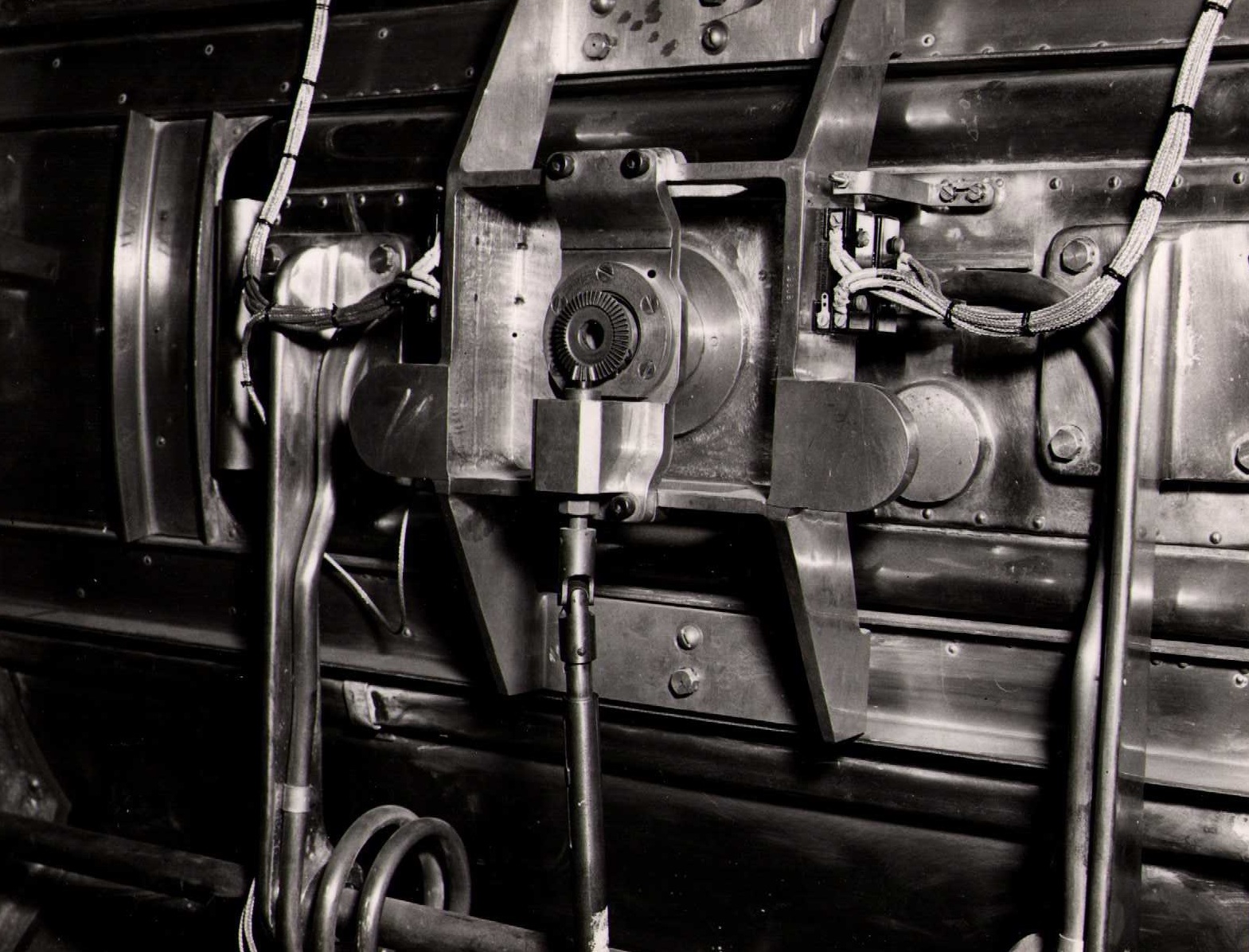
15 April 1957: Tank 1 tilt tuner -- external view
15 April 1957: Tank 1 tilt tuner -- external view
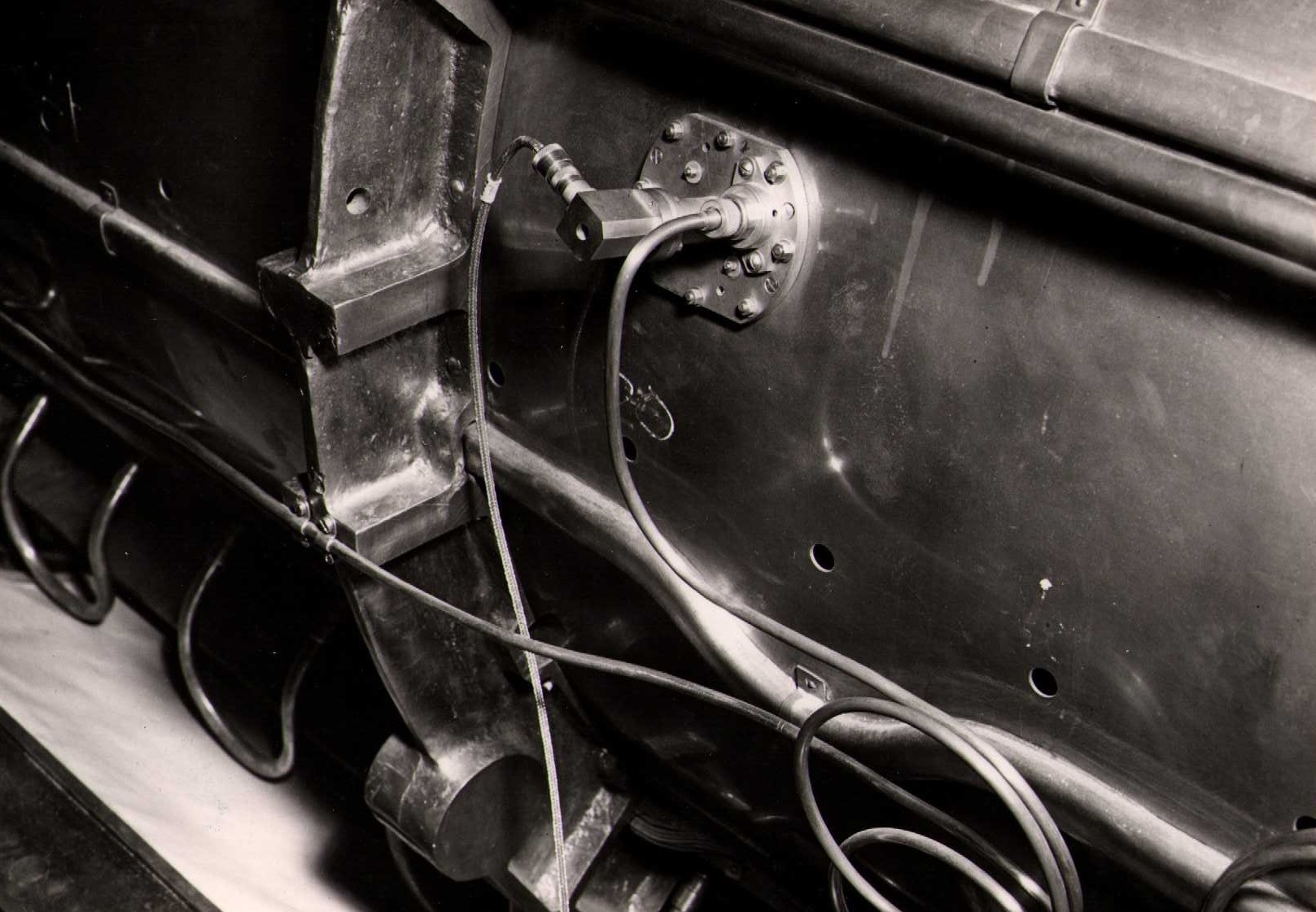
15 April 1957: Tank 1 RF power monitor
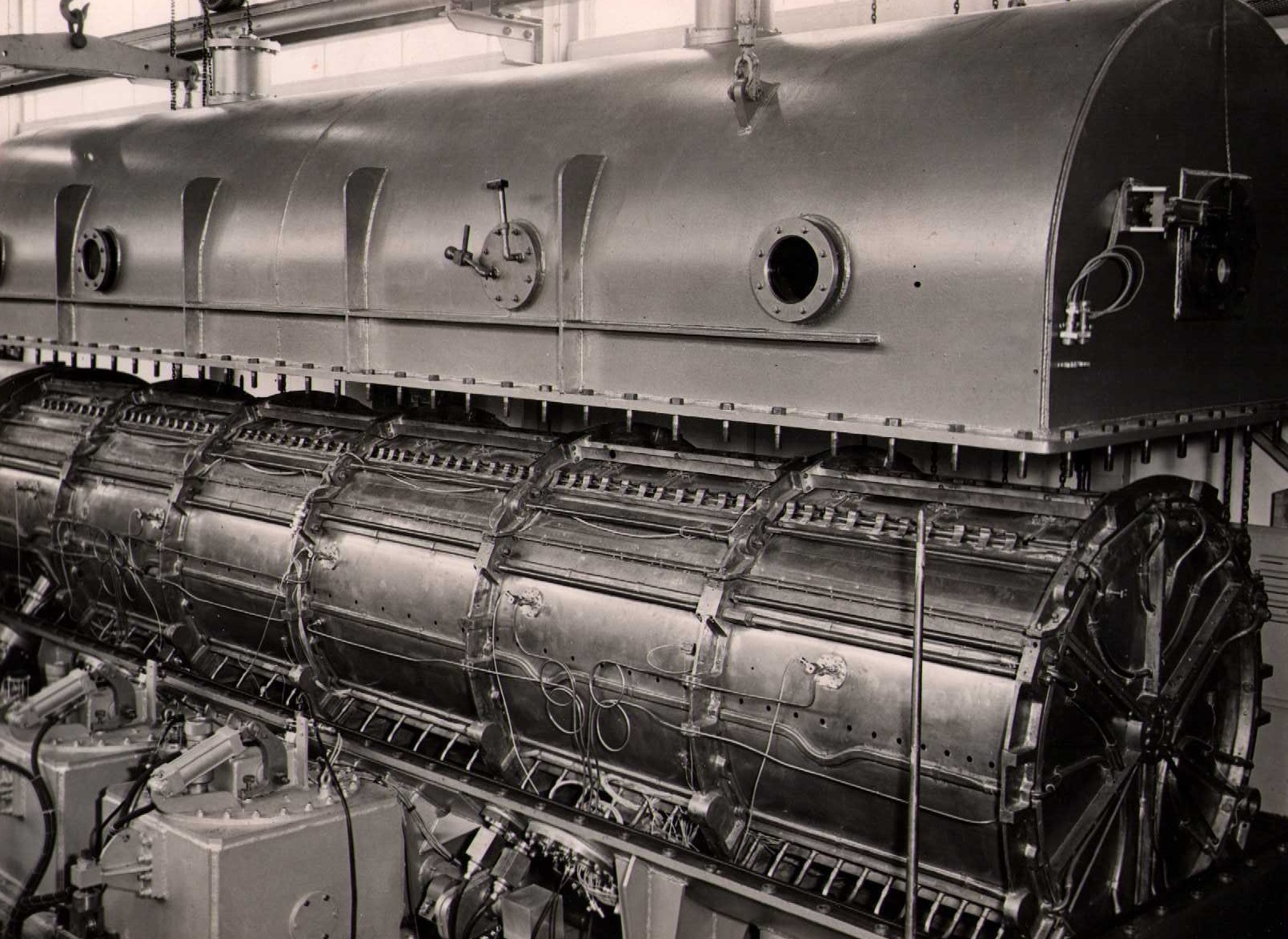
17 April 1957: Tank 1 top view of liner in vacuum envelope
17 April 1957: Tank 1 view of liner from output end on tuner grid
2 May 1957: Tank 1 vacuum envelope lid raised showing liner

 Photograph album cover