

Tony Pritchett, Open University
Introduction by Edward Goldwyn, Open University
1974
Focal Press
The television programmes of the Open University Course in Mathematics are making extensive use of computer animation. The course is a first year University level course and the animation is used in a very specialised way to illustrate mathematical concepts. We think of it as a magic blackboard. For instance, we have storyboarded films to show the effect of differencing functions. We have shown how polynomials change their shape as their co-efficients vary, how to explore a surface to find maxima and minima - and so on.
The delight for us is a freedom to display lines and perform mathematical operations on them, how we can magnify parts of the screen by ten thousand or a million at will. The curves move in so precisely a calculated fashion that you get a different effect from conventional animations - you no longer seem to be looking at a diagram which represents the equations but at the abstract functions themselves.
We commission the films in a conventional way starting with a storyboard, and then begin discussions with the computer people. Our first films were produced by John Prior of the Mathematics Division of the Culham Laboratory of the United Kingdom Atomic Energy Authority. We have continued to use them and to satisfy our demand have had to widen our field of activity. F R A Hopgood, G A England and R G Astbury of the Science Research Council, Atlas Computer Laboratory (ACL), were kind enough to help us in the early days. Jeffrey Lickess as an OU research student has handled the bulk of our animations, and Tony Pritchett has programmed some of our most complex films.
THE SYSTEM
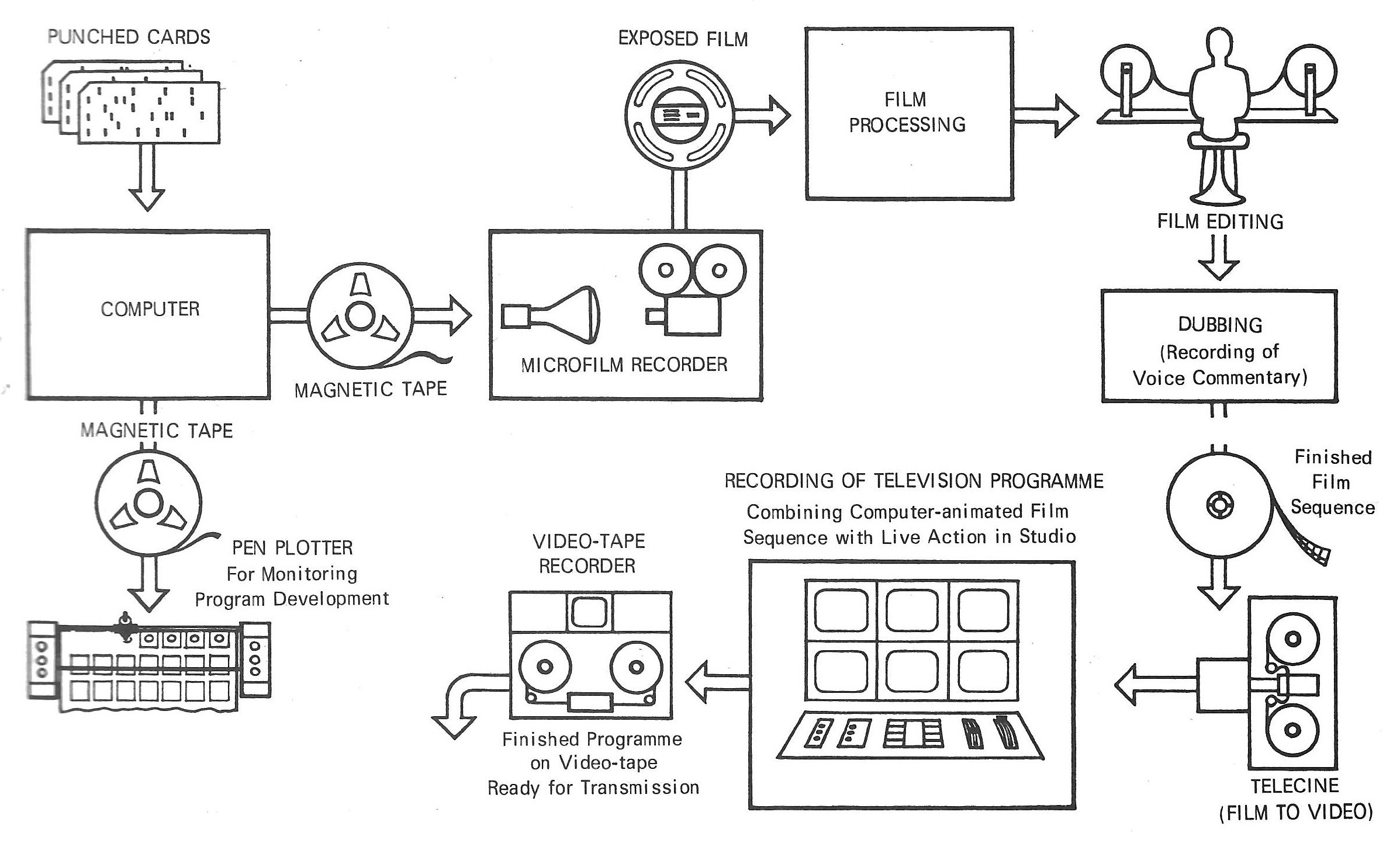
Fig 15.1: The processes involved in the making of a computer-animated sequence for an educational television programme, using an Atlas computer and a Stromberg-Carlson 4020 microfilm recorder.
Hardware
Two establishments (London University Computing Services (LUCS) and ACL) possess ICL. ATLAS I computers. ATLAS is a large multiprogram machine operated in batch-mode.
BATCH-MODE implies the kind of operation of a large computer where the user cannot directly communicate with the computer via a terminal, but submits his job as a deck of cards, or a paper tape, to an operator who runs his job for him, together with others, in a batch. He must return later to collect his output. MULTI-PROGRAM implies that there can be several programs in the computer at the same time, all at various stages of execution, and time-sharing the computer's central processor.
In addition, ACL has a Stromberg-Carlson 4020 microfilm recorder, which converts digital information into images on film. This machine essentially consists of a precision CRT display, a film camera and a magnetic tape unit (which drives the CRT and the camera). A later version, an SC 4060, is described more fully in the chapter by Taylor and Russoff.
The camera on the SC 4020 at ACL takes standard 16 mm movie film, which is the gauge normally used for film sequences in television.
The image field produced by the SC 4020 is square, and is projected on to the film so that it fills the standard 16 mm frame vertically, but does not quite fill it horizontally, (Fig. 15.2). A margin of approximately one eighth of the frame width on either side cannot be plotted on by the SC 4020, but by happy coincidence this is also approximately what must be allowed for cut-off by domestic television receivers, so that anything in this margin may not be visible anyway.
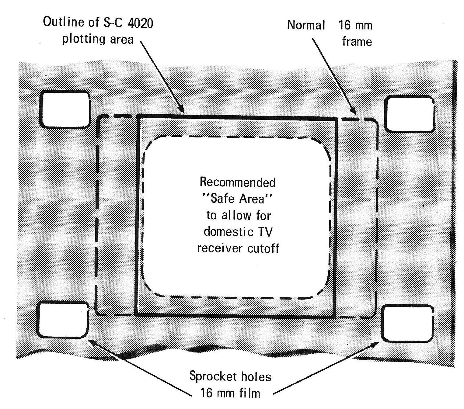
Fig 15.2: The SC-4020 plotting area on 16 mm film and its relationship to TV receiver cutoff.
LUCS has a Calcomp model 563 pen plotter. The use of this for program development is described in the next section on software.
Software
So far no attempt has been made to design a special-purpose movie language like BEFLIX. This was partly because it was felt that considerable experience was needed with whatever means were currently available before the true requirements of such a language were known, and partly due to need to get down to making films straight away (languages take time to implement). So a heuristic approach was adopted, starting with the Atlas FORTRAN SC 4020 microfilm recorder package as a basis. This was the work of Paul Nelson at ACL Chilton, and is described by him in another chapter.
The basic subroutines taken from this package which write graphical information in SC4020 code on to magnetic tape, have been gradually supplemented by a superstructure of more special-purpose movie subroutines as the need for them has arisen: (see software summary). The highest level of this superstructure is a simple data language which allows one to specify the order of events, timing and other parameters of a film in a script-like manner. Experience with that facility is of immense help in trying to formulate an ultimate practical movie language.
The SC 4020 also has a hardcopy camera, which gives images 7in square on rolls of light-sensitive paper for direct viewing. This is a convenient form of output to use during the development stage of a program. But since the programs were developed in London and the SC 4020 was sixty miles away at Chilton, a substitute method was devised, using a Calcomp pen plotter. A parallel set of subroutines were written bearing the same names as those of the SC 4020 package (VECTOR, PLOT, ADVAN, ADVREP, etc.), which simulate the action of the SC 4020 on the Calcomp. Figs 3 and 4 are examples of Calcomp output. A useful feature of this (not available on the SC 4020) is the ability to set a parameter to plot only every nth frame.
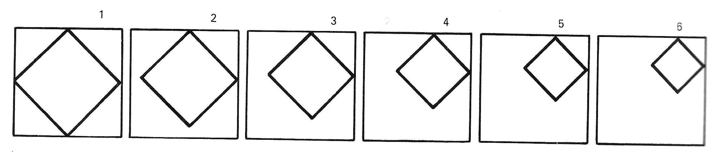
Fig 15.3: Example of CalComp output.
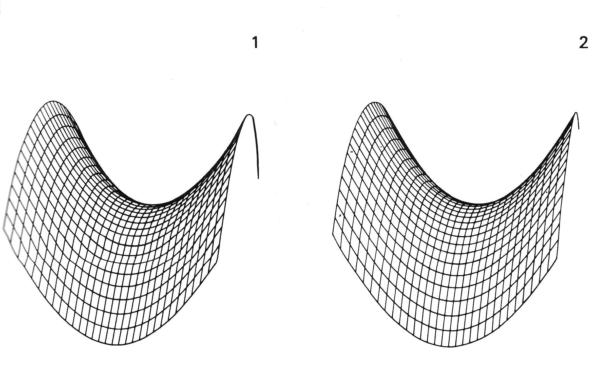
Fig 15.4: An example of CalComp pen plotter output, showing two frames of a saddle-shaped surface rotating. They do in fact form a stereo-pair which can be viewed.
The development of each film sequence is carried out using the Calcomp set of subroutines, only being replaced by the SC 4020 versions for the final production run, from which the tape is sent to ACL to be run on the SC 4020.
An example of Tony's work for the BBC is Random Walk. This version in SVG was recreated from the original card deck.
TELEVISION TECHNIQUE
It is normal practice, when making education television, for the bulk of a half-hour programme to be recorded on video-tape from a television studio, with a lecturer or presenter in the studio. There may also be one or more sequences of film included in the programme, which are mixed into the studio video channels from a telecines machine (film-to-video converter).
The processes undergone by a sequence of computer animated film from microfilm recorder to studio are as follows:
- Exposure in the SC 4020 microfilm recorder. The film stock used is Kodak Plus-X negative (16 mm).
- Processing: an ordinary positive print taken from the original negative gives white lines on a black background.
- Editing: computer animated film should theoretically not need editing. If the final timings are fixed before the main production run on the computer, the film as it comes from the microfilm recorder will be exact to the last frame. This is seldom the case, because it is easier to decide what timings ought to be after seeing the rush print and then to modify it in the cutting room. By timing, is meant the length of holds (i.e. periods of no movement), between pieces of action. In order to alter the speed of the action itself, it would require a re-run on the computer. Ideally, there should be provision for a complete computer re-run, but there is usually no time. In the cutting-room one can modify cues by chopping sections out of the holds, therefore the length of holds tend to be overestimated on the original version in order to have something to work with.
- Dubbing: the commentary which goes with a film sequence is usually recorded at a dubbing session before the actual studio day. The presenter sits in the dubbing theatre while the edited film is projected, and he records his words on to a sound track synchronized with the film. This way it is easier to make the words fit the pictures accurately (as it can be re-done to perfection), and it gives a few minutes' break to the presenter in the studio.
Fig. 15.5 is a flow diagram of the whole process of making a computer animated insert for a television programme, using a batch-mode computer, with approximate times for each stage.
Fig 15.5: Flow-chart of producing an animated film for television using a batch-mode computer and microfilm recorder.
POSSIBILITIES OF INTERACTIVE SYSTEMS
Imagine a television studio during camera rehearsal of an educational programme on mathematics.
The monitors in the control room show a presenter talking about surfaces and their maxima, minima and saddle-points. The director, seated at a console in front of the monitors, calls Mix to computer. The presenter's face fades from the main output monitor and is replaced by the first frame in Fig. 15.6. The presenter continues over the new picture: Let's take a closer look at the mathematics and see what's going on ...
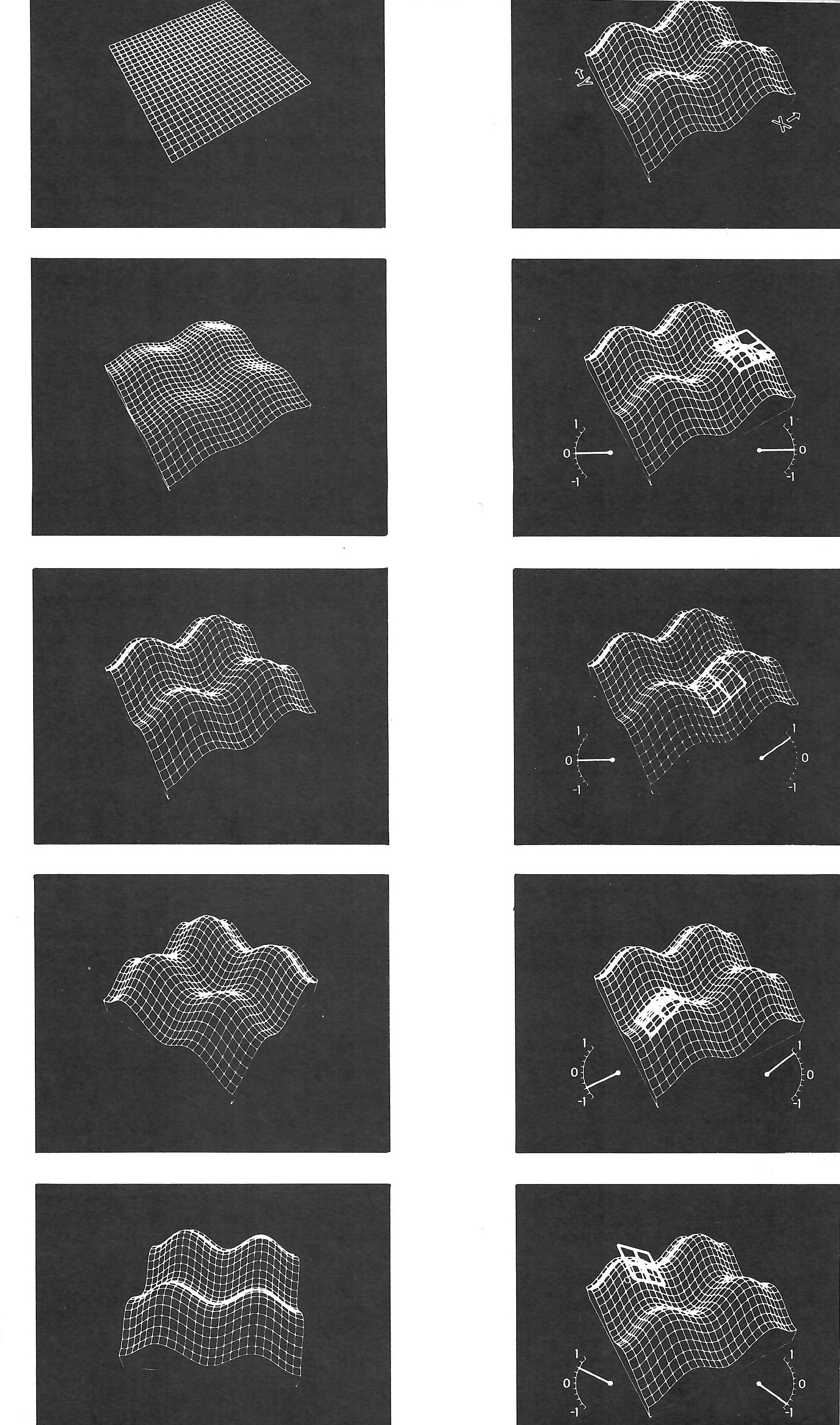
Fig 15.6: Animation in three dimensions without using models is only practical by computer. Reproduction here are several frames from a film sequence for the Open University Mathematics Foundation Course M100 (unit 15) 'Differentiation II: On the Surface' about partial differentiation and how to look for maxima, minima and saddle-points. A tangent plane explores the surface while two meters indicate its slope in the X and Y directions. The moved surface is conceived as a mathematical function (z = -a(cos x + cos y) in three-dimensional space, from which a suite of trigonometrical subroutines produce a drawing in true perspective from any desired viewpoint.
The director calls Animate and an operator sitting at another console in a corner of the control room touches a button, and the grid gradually grows four humps and then rotates. Here's a surface - the graph of some function F ... a line appears and moves across the surface ... this little line is a tangent line to the surface, and .. . Can we hold it there? the director interrupts into the talk-back microphone, and turns round to address the computer operator who has frozen the animation at the touch of another button. Is it possible to hold the tangent line for a few seconds after it jumps in, instead of having it moving straight away? The computer operator replies: Yes, but it'll be hard to see when stationary, it'll get lost among the other lines of the surface. Director: Can we make it thicker so that it stands out?'
The operator nods, points at the tangent line with his light-pen, types something on a keyboard - and the surface momentarily disappears, and reappears with a thicker and brighter tangent line.
The directors says OK, that's fine, start again, from the top of the computer sequence, Shot 17. The computer operator types RESETQ 17,0 and the bumpy surface changes back to a flat grid. Cue studio. The presenter's voice begins again, Let's take a closer look at the mathematics .. .
The piece of computer animation just described exists; only the method of producing it was imagined. Computers in television studios generating animation interactively in real time do not exist at the time of writing, but most of the hardware to achieve it is available.
Already there is talk of the automated studio incorporating a computer, to which an instant animation device would be a natural peripheral.
An interactive system would give to computer animation the sort of spontaneity and dynamic flexibility that is needed in the television situation. The detailed contents of a programme are sometimes quite drastically altered between the first camera rehearsal in the morning and the recording later in the day. Using ATLAS and the SC4020, the decisions taken in the studio in the imaginary situation related above had to be taken two weeks before the studio day and without knowing what they would look like on a television screen.
Fig. 15.7 shows a likely configuration for a fully interactive system. The main time would be in stage 2 (development) of the off-line method (Fig. 15.5), which could be replaced by few hours' work.
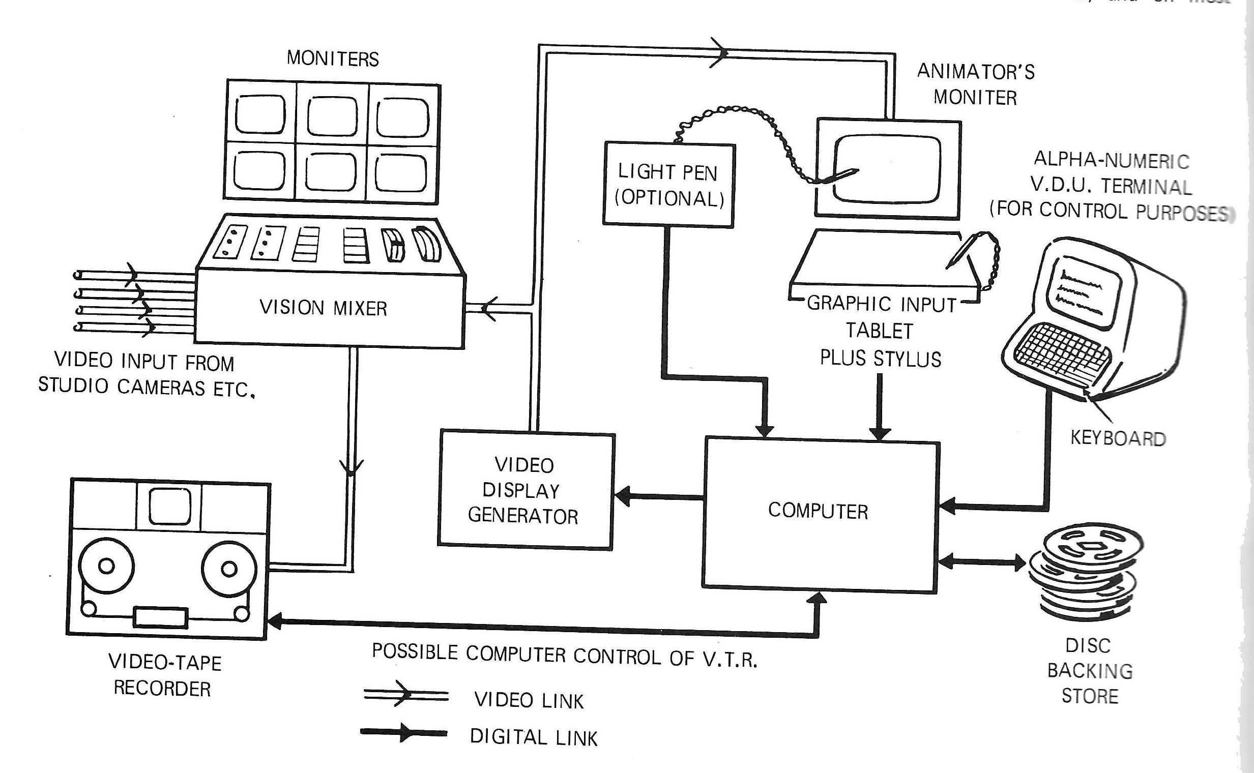
Fig 15.7: Possible configuration of an interactive computer-animation system in television line-scan ('video') format, a TVcompatible line-scan based graphics system would be used. Current practice in interactive graphics is to have a small satellite computer to handle the display, on line to a large, powerful, time-sharing computer to do most of the processing. However, the random time delays caused by time sharing would pose a problem for real-time animation, so the application suggests a single, fast, dedicated processor in the small-to-medium size range, with a fast disc backing store.
The cost of producing film using a batch mode computer works out approximately equivalent to the conventional method, at the time of writing. However, it is very difficult to make direct comparisons because most things which are worthwhile animating by computer are too difficult to tackle by other means, and conversely any attempt to get identical results to a piece of conventional animation by using a computer would be practically impossible.
One of the snags with computer-generated film at present is its limited graphic style. Existing picture-generating hardware uses dots and straight lines as basic picture elements, and on most machines curved lines must be approximated to by straight line segments. A fair proportion of the cost in computer time is directly related to the total number of these elements generated. It is true that pictures of any desired sophistication can be reproduced digitally by the mosaic approach using a sufficient number of the basic elements.
A digitised television picture, assuming 600 × 800 resolvable points each with sixteen possible brightness levels, contains approximately 2 million bits of information.
Multiplied 24 times for each second's worth of film, to produce movies by digital computer with a mosaic of television resolution is very expensive in computer time. So in practice one is limited to simple line drawings.
Here is an actual example of how one is penalised for quantity of information. For one of the BBC sequences it was originally intended to shade about 30 per cent of the area with evenly spaced dots. It is estimated that there were in the region of 50,000 dots in each frame. In a trial computer run, it came to the end of a complete 2400 reel of magnetic tape and used over five minutes of cpu time in generating only twelve frames. After a rough guess at how many tapes and how much time it would take to complete the sequence, dot-shading was abandoned and plain outlines were used instead.
For comparison, the sequence illustrated in Fig. 15.6 representing over four minutes of film, clocked up twenty minutes computing (cpu) time in the final run, and generated 3½ reels of magnetic tape which took five hours to run on the SC 4020 film recorder. Roughly a quarter of the sequence was taken up with holds (i.e. no movement) where the SC 4020's repeat frame facility was used, which enables a single frame on the tape to be plotted up to 32 times, requiring only one frame to be generated by the computer for every 1¼ seconds of hold. Each frame contained about 3500 vectors (straight line segments). For the parts where the surface itself grew or rotated, the whole surface had to be recomputed for each frame, taking approximately ten seconds of computing time each.
I expect that the greatest saving in the use of an interactive computer system will be in the time taken to produce a film, which could be reduced from weeks to days, or even hours.
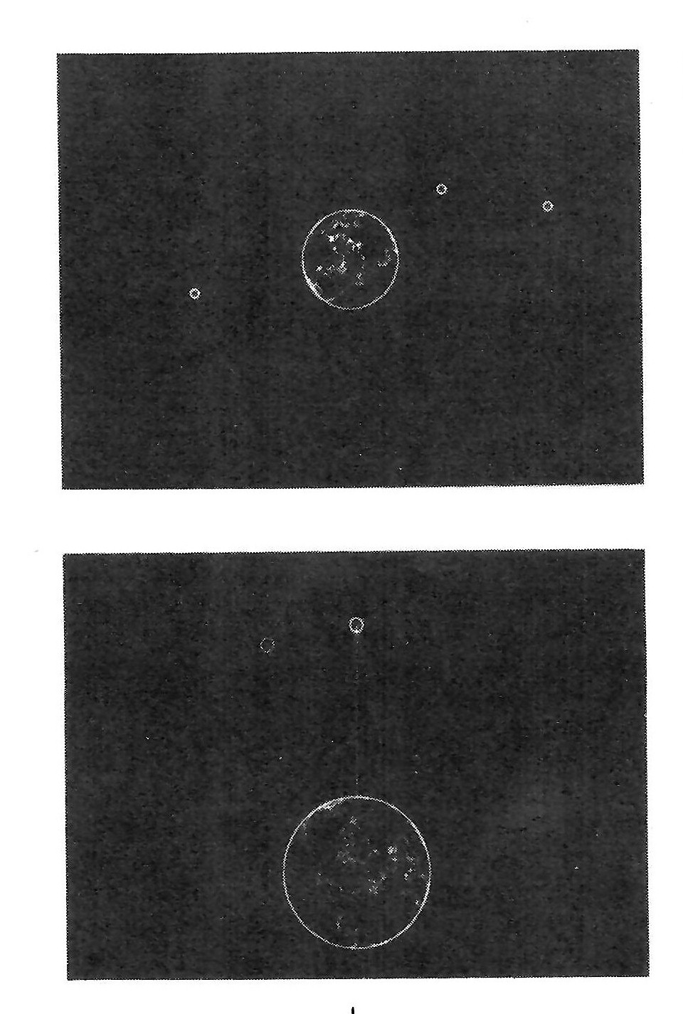
Fig 15.8: Example from Open University television programme: Technology Foundation Course T100 satellite case study: The How of Project SACI, demonstrating how to get an educational television satellite into a 'synchronous' orbit round e equator so that it always remains above the same point in the north of Brasil.
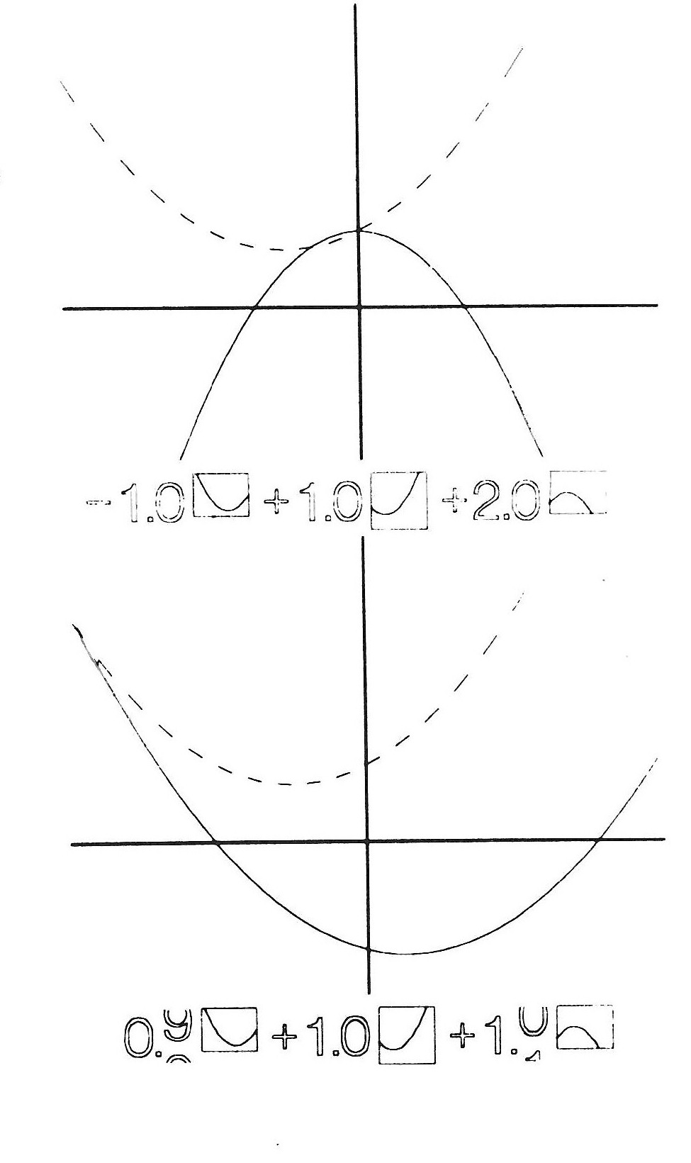
Fig 15.8b: Example from Open University television programme: M201 Linear Mathematics course, programme 1 What Is Dimension?; showing how one can match any quadratic curve by finding a suitable combination of three others with suitable co-efficients change with the solid move in cyclometer fashion.

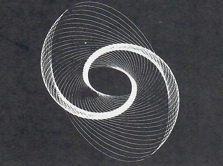
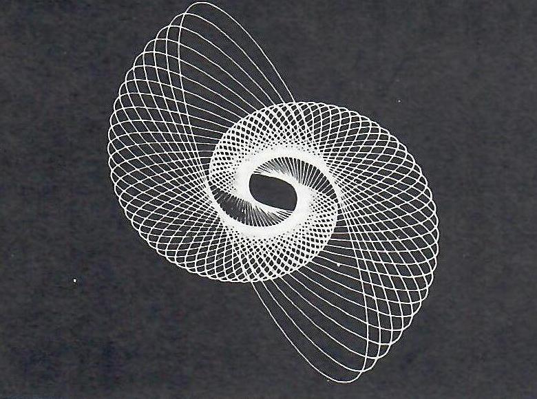
Fig 15.9: A non-educational animation by the author: (a) An animated soap-powder logo;
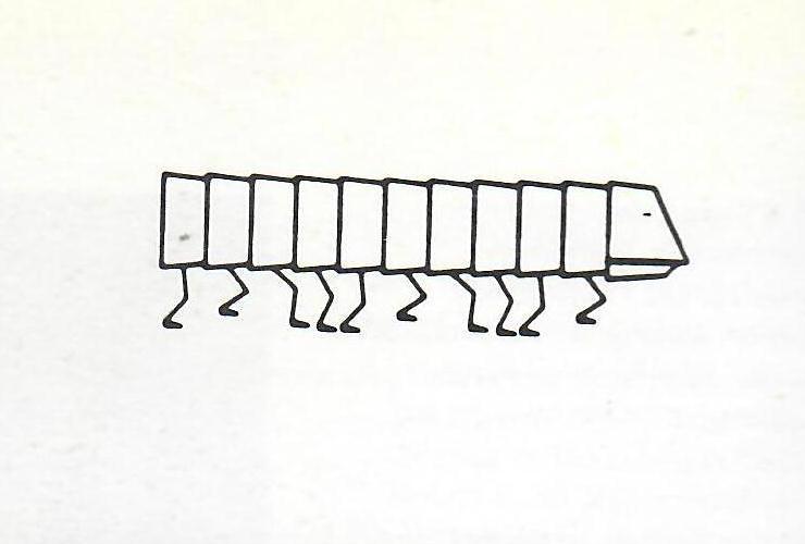
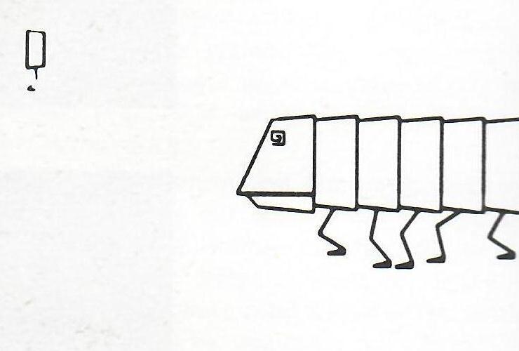
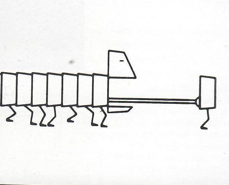
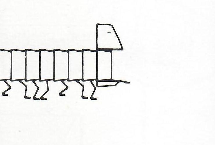
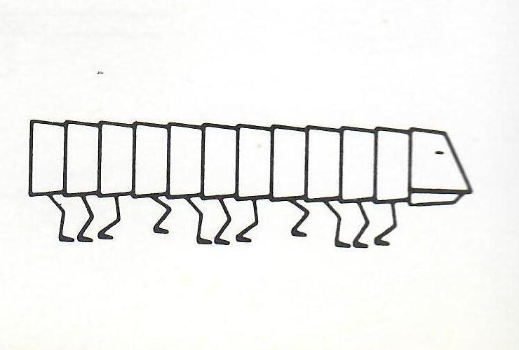
Fig 15.9: A non-educational animation by the author: (b) The Flexipede.
FUTURE OF COMPUTERS IN GENERAL ANIMATION
Computers are getting cheaper, or to be more accurate, the amount of computing power for a given cost is increasing quite fast (30 per cent per year is a popular estimate). Many uses for computers in animation which are at present considered not to be cost-effective may very soon become so.
A way of getting round the graphic limitations of computer film is to employ a hybrid technique where part of the process of animation is done by computer, but the images end up on cels and are shot on a rostrum camera in the normal way. A example of this is a title sequence I made for the film WHAT IS A COMPUTER? produced by John Halas and directed by Stan Hayward (Fig. 15.10). In this sequence the computer worked out the transformations from one bank-cheque numeral to the next and plotted each frame in outline on paper with a Calcomp pen plotter. The plotter output was then traced on to cels and coloured in by hand. It is unlikely that anyone would have bothered to work out the transformations by hand in quite the same way.
The original deck of cards that produced this animated countdown was still in Tony Pritchett's possessions when he died. A reconstruction of the program, called SLURP, has been made available.
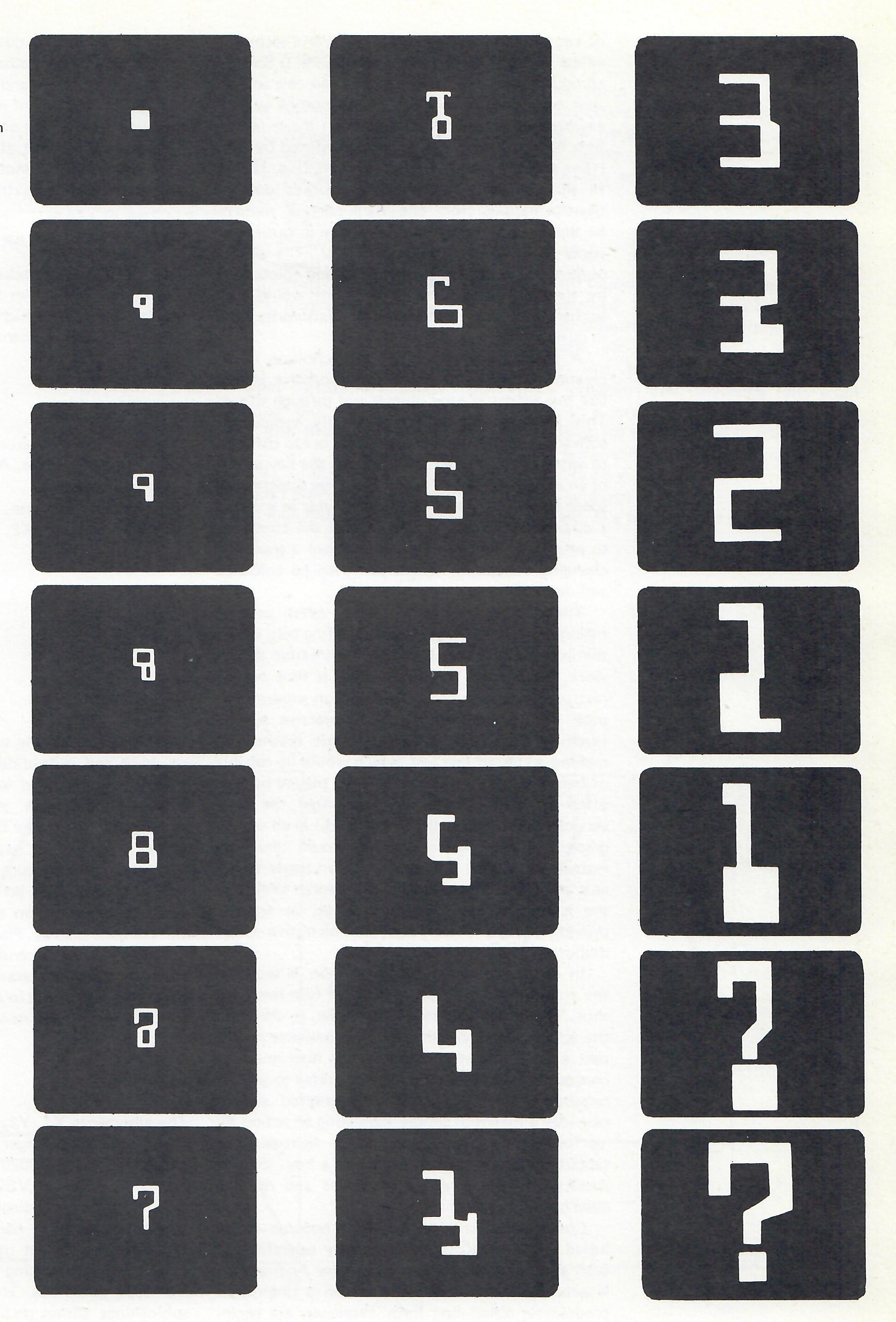
Fig 15.10: The countdown title sequence from the Halas and Batchelor film What is a Computer? The outline figures were drawn by computer and then painted in by hand. Shown are 11 key frames and 10 'inbetween' frames.
A good use for this hybrid technique is the creation of three-dimensional perspective effects like movement around objects and through spaces. This is something which is usually avoided in conventional animation because it is too difficult to work out frame by frame. Once the key points of an imaginary object or set in three dimensional space have been given to the computer as x, y and z co-ordinates, it is a trivial job for the computer to plot outline perspective views from a gradually changing viewpoint, which can then be coloured and detailed by hand.
There is an intermediate stage often used in making animated films known as a line test, where the initial outline versions of the animation artist's work, uncoloured and undetailed, is shot on the rostrum camera in order to check on movements, pace and overall effect. An interactive system (such as Baecker's) provides a fast method of making a kind of line test, which would be capable of being modified and immediately played back as often as desired, until it represented the final version of the film (with sound track) in all except graphic detail. The computer could then be instructed to plot the whole film on paper to act as a template for the artists in a manner similar to the hybrid system described above, as well as providing dope sheets and administrative information.
In conventional animation, action is seen for the first time only when a piece of film has been shot. This is the purpose of a line test, to check on the action; and it requires much experience on the part of the animator to know just how much to change the picture from frame to frame to get the required effect. An interactive graphic system provides a means of simply indicating an action by performing it with a stylus or light-pen, or tapping out a rhythm of events on a key. (See R Baecker on movement descriptions and rhythm descriptions).
Computer animation has now become established in the BBC Open University operation to such an extent that Order Computer Animations' is actually included as an item on a preprinted programme scheduling form. Producers are beginning to rely on it for things that would be difficult or impossible to do by any other method, particularly in mathematics (e.g. the three-dimensional surface and tangent plane (Fig. 15.6).
With the coming of interactive systems, it seems likely to spread into other areas of television, sue as news and current affairs, where the ability to produce simple animated maps and diagrams at short notice will be extremely useful.
SOFTWARE SUMMARY
The FORTRAN package used to produce the Open University film sequences has evolved on several levels. The higher levels are in a state of continuous development and extension as the need arises.
Level 1
The basic set of picture-constructing subroutines are a subset of the ACL Chilton FORTRAN graphics package.
The principal calls are:
VECTOR (X1, Y1, X2, Y2)   plots a line from point (X1, Y1) to
                          point (X2, Y2) on the SC 4020 grid. plots a character C (appears as a dot on 16 mm film) at point (X, Y) advances film to next frame.

PLOT (X, C, Y)            plots a character C (appears as a dot
                          on 16 mm film) at point (X, Y)
ADVAN                     advances film to next frame.
The coding of the subroutines at this level are machine and output-device dependent, and thus represent a back-end which must be rewritten for different computers and graphic devices. The original set generates SC 4020-coded tapes from Atlas. There is a set (with the same names) which generates Calcomp plotter tapes from Atlas simulating the SC 4020 on paper, and a set has also been implemented on a PDP-9 with a Computek storage tube display. Plans include implementation on the CDC 6000 series computer for microfilm, paper plotter and interactive VDU output. Everything above level 1 is in ASA standard FORTRAN, which is fairly machine-independent.
Level 2
The arguments X1, Y1, X2, Y2 of the subroutine VECTOR are of integer type and refer directly to points on the SC 4020's 1024 by 1024 picture matrix (e.g. CALL VECTOR (0, 0, 1023, 1023) would plot a line diagonally across the plotting area from corner to corner). This is not so useful as being able to set up any desired co-ordinate system for the plotting area and specify points as real type quantities. Therefore the next layer of subroutines allows picture-construction in user-defined co-ordinates.
For example Fig. 15.11 (left) could be plotted by the following instructions:
      CALL DEFMAP (-2.,0.,2.,4.)       defines l.h. bottom corner of plotting
                                       area to be (-2,0) and
                                       rh top corner to be (2,4)

      CALL PLACE (-2.,0)               Starts new line at (-2,0)
      CALL LINE (0.,4)                 plots line to (0,4)
      CALL LINE (2.,0.)                plots line to (2,0) from end of last line.

      CALL PLACE (-1.5.,1.)
      CALL LINE (1.5.,1.)
Windowing (also called 'scissoring) which renders invisible everything plotted outside a defined rectangle, is built into the system at this level.
e.g. If CALL WINDOW (-1., 1., 0.5, 3.5) were to be inserted after CALL DEFMAP in the above example, the picture would look like Fig. 15.11 (right).
Level 3
At this level there is a library of subroutines, which is constantly being expanded, for doing such things as perspective projections of three-dimensional figures, and a graphically acceptable software character set (Helvetica) for captions and labels.
Level 4
Animated film sequences are usually made up of a complex sequence of events, such as objects appearing, disappearing, moving from A to B, changing shape, etc., interspersed by holds (no movement). This becomes unwieldy at the FORTRAN program level, involving long main programs, with a large number of DO loops, so a simple data language was invented to enable one to specify the sequencing and timing more easily, as in a script or dope-sheet.
The data language is a series of commands, one per line or card, in a fixed format as follows:
Col No 1      2-6                  7-16          Meaning
Function      Name                 Numerical
Code          Field                Parameter

+             <object>             blank         Introduce <object>, (static)
/             <object>             blank         Introduce <object>, (dynamic)
-             <object>             blank         Remove <object>
space         <process>            A             Perform <process>, (IA is an optional argument)
*             <process>            T             ACTION T seconds ie generate T secs of film,
                                                 executing <process> for each frame
H             blank                T             HOLD: T seconds
=            <real variable>       X             <real variable>:=X
.            <integer variable>    X             <integer variable>:-X (truncated)
)            blank                 blank         End of Film
The difference between Introduce (static) and (dynamic) is difficult to explain without a deeper knowledge of the system.
The main program reads in the data language, or script and interprets it sequentially.
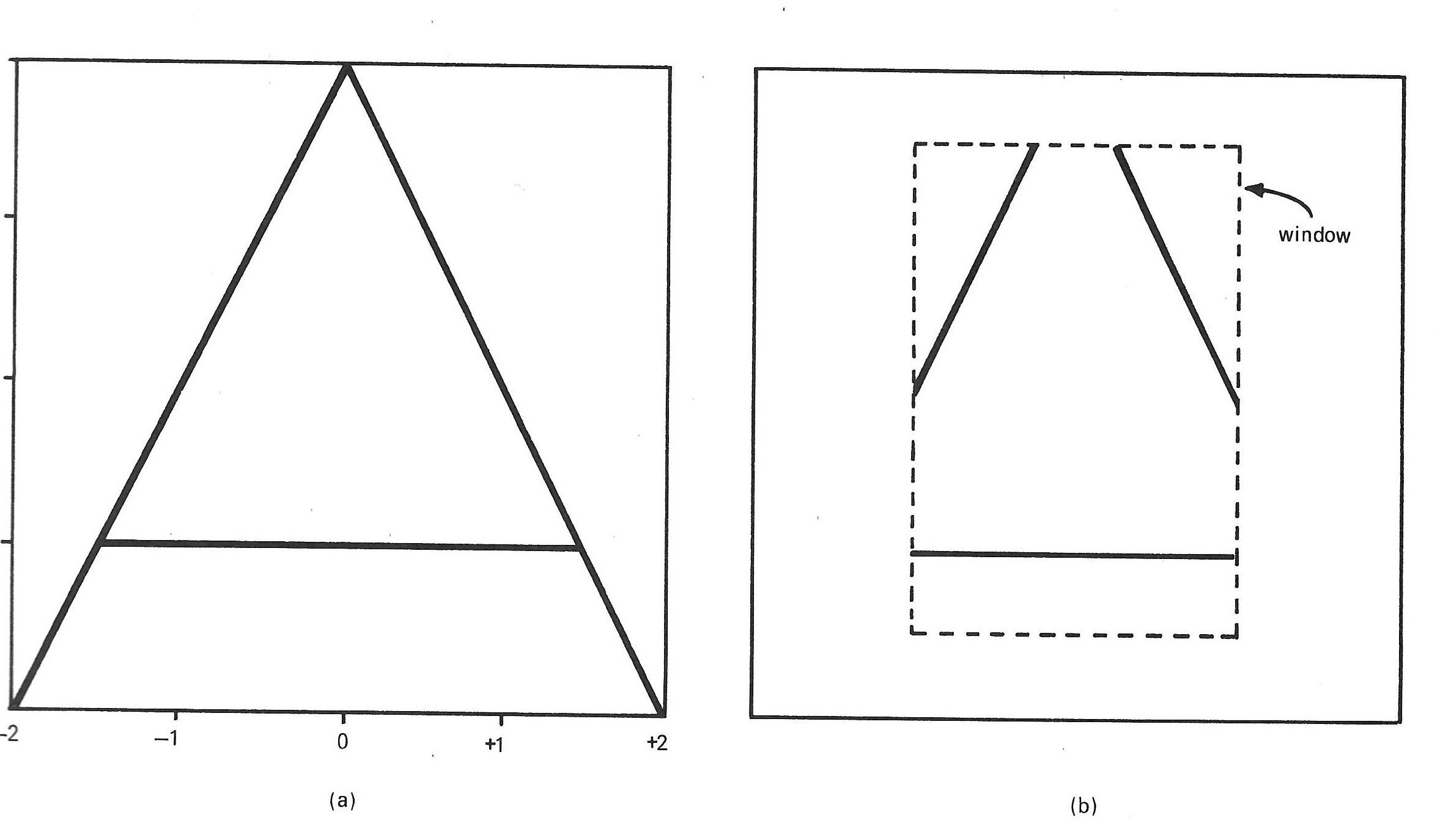
Fig 15.11