

M Russoff and F A Taylor
1974
Focal Press
The various applications of computers in film production may be briefly summarized as follows: Films using computer assistance: These may be produced by:
- Using a pen type plotter to draw the required diagram, which is subsequently photographed.
- Using a special purpose device - in particular the Stromberg-Carlson 4020 or 4060 plotter, or its equivalent available from other companies, producing records on film directly.
Films using the computer to generate 'animation'.
The computer can be used:
- Simply as a drawing aid for the production of diagrams built up from regular geometrical figures, or figures capable of mathematical description. Only a small number of strategic drawings need to be programmed - these sub-programs can then be called at will to produce combinations of such figures.
- This scheme can be extended by allowing the production of films which are animated in three dimensions (i.e. the subprograms already mentioned above, corresponding to particular figures, have an added facility which allows them to be rotated and thrown into perspective, to give the effect of a third dimension).
- Films representing given mathematical functions, normally time-dependent functions (such as the collapse of a dam) can be produced, using the mathematical equations describing such a phenomenon as a basis.
In a pilot study undertaken by the National Computing Centre Ltd. in conjunction with Halas and Batchelor Cartoon Films Ltd. it was decided that, as far as the United Kingdom was concerned, it was best to concentrate on the educational area for the time being. Experimental work would combine techniques b and c outlined above (i.e. producing a film-for-education use which involved handy two dimensional figures which were rotated, effectively having three dimensions, the figures themselves being mathematically definable curves).
Programming work was undertaken at the NCC-unit and all programs generated were run on the Atlas 2/SC4060 system at Aldermaston, so that the system software already existing at that establishment for the SC plotter could be used as a basis.
The following chapter details the storyboard chosen and the techniques chosen (hardware and software); Operational aspects of the experiment and the economics of the project with a comment on future economics and plans.
In connection with economic considerations, it was decided to attempt to ascertain just how much faster films could be prepared using computer assistance, and by how much manpower requirements were reduced in the dimension of tedious manual drafting.
COMMERCIAL EXPLOITATION
To test the commercial possibilities of this technique a suitable education subject had to be selected. It was decided that the aim should be a film designed to teach the mathematical concepts associated with the pole and polar of a conic section, in this case an ellipse. (The incremental cost of producing further films, once the techniques are established, is discussed later.)
The ultimate objective was to produce films for screening on the small back-projection monitor units, resembling a television receiver, available to teacher and pupils in a classroom. The final film was to be in 8 mm form and made up as a continuous loop mounted in a cartridge which is placed into a slot in the projector. No complicated threading or rewinding of the film is required.
THE STORYBOARD
The conventional way of producing animated films is to draw and then expose the film frame by frame. If the film content is mathematical, then elaborate calculations must be made before any particular frame can be drawn. Occasionally, the necessary calculation may be so long and laborious as to preclude any attempt to produce such a film using conventional techniques.
It is in such a situation that computerized animated techniques score over conventional methods. The calculating power of the computer can be used to determine the state of a particular motion sequence frame by frame, and using the microfilm and recorder described above, eliminates even the necessity to draw up and then film these frames.
The storyboard of the film produced during this feasibility study (see Fig. 4.1) is of a precise geometrical nature that would enable it to be produced fairly easily by conventional techniques, but also involves sufficient mathematical calculation to render it suitable for computerized animation, thus enabling a direct comparison to be made between the effort and costs involved in both manual and computer production methods.
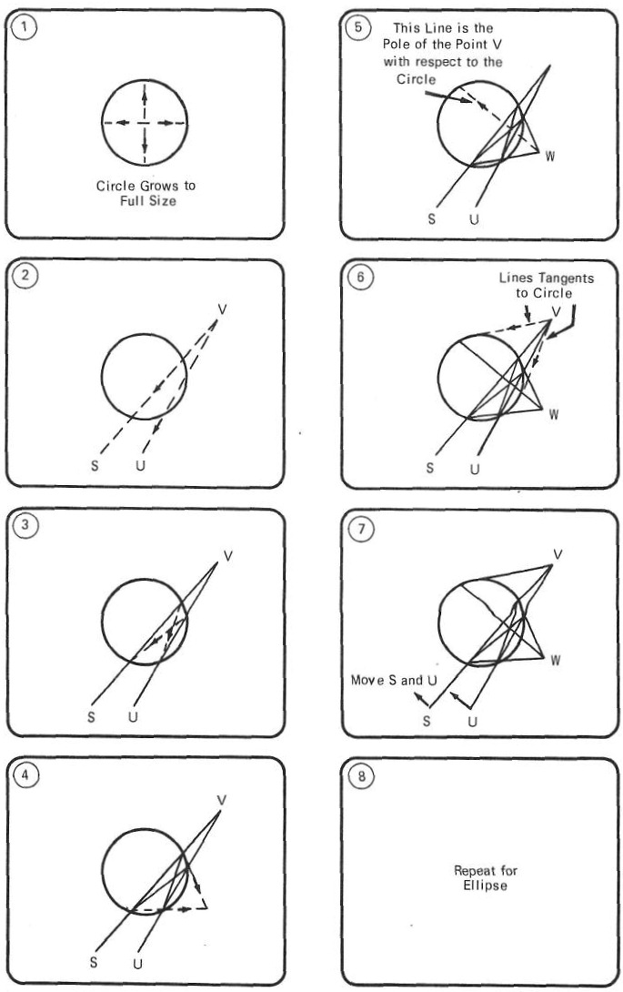
Fig 4.1: The basic construction, illustrated by the film Pole and Polar, is shown in the storyboard
One can envisage other subjects (e.g. moving lines of force fields around magnetic poles) which involve much calculation to describe, and which are not precisely defined geometric shapes that are easily drawn using a compass and ruler. In this case, computerized animation would be the better and possibly only method of producing the film. Again, there are other subjects with little or no mathematical content which are better animated using conventional techniques.
There is another benefit from using computerized techniques. The programs to produce the film are written in a general form and it is only at run time, when the magnetic tape for driving the microfilm recorder is being written, that the actual co-ordinate positioning information of the figures in the film need be specified. This means that after producing one take if the size or shape of an item to be altered, the program can be simply run again with new co-ordinate data to produce the next take. Using conventional methods, the whole film would have to be recast or redrawn, frame by frame, to incorporate such changes, whereas precise positions can be specified very quickly using computer techniques.
In this case, it was decided to produce a short film titled Pole and Polar. The basic construction illustrated by the film is shown in the storyboard diagram in fig. 4.1. The sequence is first constructed for a circle and then repeated for an ellipse. Finally, keeping the lines VU, VS fixed, the ellipse is gradually changed into a circle and then back to an ellipse again, to illustrate the general nature of the construction. The sequences are interspersed with titling, which has also been produced automatically on the microfilm recorder.
TECHNIQUES: HARDWARE
The production method made use of a microfilm recorder. A precision cathode ray tube is situated optically in front of two cameras, one of which exposes 35 mm microfilm, while the other produces hard copy output on photographic paper.
Either or both cameras can be chosen automatically by program commands.
The complete optical system is housed in a light-proof enclosure and the camera shutter mechanisms are held open all the time. The film or photographic paper is advanced by program commands, during which time the face of the cathode ray tube is automatically blanked off.
When the new frame of film or paper is in position, the control electronics expose that frame by displaying graphic information serially, once only, on the face of the cathode ray tube. The positioning of this information on the face of the tube is defined by a 1024 × 1024 matrix of addressable points and the electron beam can be deflected to draw straight line vectors between any two of these points. In this way, pictures can be built up from such vectors, and as each vector is displayed it will be recorded on the frame of film or paper currently in position. When the complete picture has been built up, another frame advance command is given and the next frame will be brought into position ready to be exposed.
The microfilm recorder is driven by information read from a magnetic tape. Such tape contains frame advance commands as well as co-ordinate information associated with expose commands. It is prepared by using a computer, for which a program package capable of generating commands to drive the microfilm recorder has been written.
In this case programs are written in a dialect of Fortran 2 for running on an ICT Atlas 2 computer. The microfilm recorder is a Stromberg-Carlson SC4060 operated as a SC4020. The latter is an earlier model for which the necessary program package is available. The equipment used was that at A.W.R.E., Aldermaston.
TECHNIQUES: SOFTWARE
The software used consists of a main program, which calls several system and user-generated subprograms.
Main Program
The structure of the main program of a film is shown in the flowchart - Fig. 4.6 where three names are mentioned. The function of these names is as follows:
-
MODE - this will appear in a Fortran statement
at stage 3 as,
CALL ADVFLM (MODE)If MODE is set:- Equal to 1 (at stage 1) the microfilm camera will be selected and advanced, or,
- If set equal to 2, the hard copy camera will be similarly activated.
- FRAMES - in general a storyboard will consist of a sequence of scenes each of which can be described at stage 4. Thus the main program flowchart in general will represent the filming of one of these scenes, and the variable FRAMES will determine the number of frames of film produced for that scene. For 35 mm film, the projection rate is 24 fps, and FRAMES will determine how long the scene will last when projected. It is possible to film successive scenes by linking together a number of main program segments.
-
COUNT - this variable is incremented every time
a frame is produced (stage 6) and is used to
determine when the scene has been completed
(e.g. COUNT = FRAMES). COUNT is also used in stage 4 to
calculate the intermediate co-ordinate values of figures that
are moving during the scene.
If, say, the end of a line is to swing between two points A and B, (Fig. 4.2) then the X co-ordinate of the end of the line during the scene is given by:X = XA + (XB - XA) * COUNT / FRAMESWhen COUNT= FRAMES, X = XB. COUNT is initialized at stage 2.
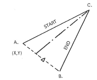
Fig 4.2: Calculating the intermediate values of figures that move during the scene; in this case the end of a line is to swing between the two points A and B.
Stage 5 details (see flowchart, Fig. 4.6)
The interface between the user's Fortran program and the microfilm recorder is a program package which includes subroutines that can be incorporated in the user's programs and will, as a result, produce a magnetic tape output written in a format suitable for driving the recorder.
The basic subroutine provided in this way is VECTOR. This appears in a Fortran program as:
CALL VECTOR (X1, Y1, X2, Y2)
If an imaginary Cartesian co-ordinate system is assumed on the face of the cathode ray tube (Fig. 4.3), then this statement causes the electron beam to be momentarily deflected between the points (X1, Y1) and (X2, Y2) thus producing the line on film or paper. The orientation of the axes with respect to the film is given later.
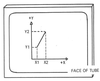
Fig 4.3: An imaginary Cartesian co-ordinate system assumed on the face of a cathode-ray tube.
As explained earlier, the addressable points are arranged as a 1024 × 1024 matrix so that the variable parameters specified with the VECTOR subroutine should be restricted to:
      0.0 ≤ X ≤ 1023.0
      0.0 ≤ Y ≤ 1023.0
These parameters in Fortran should be real variables (i.e. should not begin with the letters I, J, K, L, M or N) but since the fractional values have no meaning, it is as well to truncate the fractional part. For example, if XCORD1 is a variable within the user's program, a statement such as:
X1 = INTF (XCORD1 + 0.5)
should appear, X1 and not XCORD 1 appearing in the VECTOR subroutine statement. If XCORD1 = 241.385, then the value inside the bracket will be 241.885 and X1 will be assigned the real value 241.0 (INTF is a standard Fortran subroutine which takes the integer value of the contents of the brackets which follow it).
The orientation of the co-ordinate system on the film when the basic VECTOR subroutine is used is with the positive X axes along the film.
Since for animation, the pictures on successive frames must appear one beneath the other on the film (and not one next to the other), and also since it is more convenient to think of the X axis as horizontal and the Y axis as vertical, a co-ordinate transformation is made to re-orientate the axes suitable for stripchart or movie film. This re-orientation is obtained by writing VECTOR statements as:
CALL VECTOR (Y1, 1023.0 - X1, Y2, 1023.0 - X2)
It may also be necessary to ask the operator to set the microfilm recorder to strip chart mode, so that a frame is produced every fifth sprocket hole. In the microfilm mode it is usual to produce a frame every seventh hole.
The area on the film over which the microfilm recorder can expose graphic information does not correspond to the standard 35 mm image area. In order to expose only that part of the microfilm recorder frame that corresponds to the standard 35 mm image area, a further restriction is placed on the co-ordinate values allowed. This restriction is:
      0.0 ≤ X ≤ 1023.0
      0.0 ≤ Y ≤  818.0
This area is known as the working area.
Also, due to the presence of a sound track on standard 35 mm film, the central point of the projected area does not correspond to the central point of the working area. To obtain pictures centrally on the screen, these pictures should be centred about the point -
      X = 579.0
      Y = 384.0
OPERATIONAL ASPECTS
Below a summary of some of the problems encountered in producing the film.
There are five main stages in the commercial production of films, using the techniques described in this report. These are:
- Choice of suitable storyboard subjects.
- Detailed specification of the storyboard so that the general programs can be written.
- Writing the programs and debugging by computer runs using the hard copy camera.
- Computer runs with suitable data to produce the final film.
- Final processing and editing of the film.
This work will, in general, be split between the film maker and the systems analyst/programmer, and as in all other computing activities it is important that each appreciates the other's needs and has sufficient information to carry out his part of the work correctly. In particular, the film maker must appreciate the criteria for choosing suitable storyboards, and must then be able to hand over a detailed storyboard. Information such as image positioning and size, and the timing of the various sequences, is not needed until stage (d), when this information can be read in at computer run-time.
Software difficulties
Each category of storyboard subject requires a number of special subroutines to be written. The main subroutines written for the film described in this report are JOIN, ELLIPS and ELLCUT. The difficulties met in writing these subroutines were as follows:
- JOIN
- This subroutine was written to ensure that only co-ordinate values that lie within the 1024 × 1024 matrix of addressable points are specified with the systems subroutine VECTOR.
- The effect of using VECTOR with co-ordinate values outside
this matrix (Fig. 4.4) is undefined, and in
any case will vary with different plotting systems. With the system
software supplied for the SC4060 spurious outputs of the part of
the line outside the addressable region can be obtained.
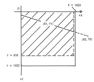
Fig 4.4: Spurious output: the effect of using VECTOR with co-ordinate values outside 1024 × 1024 matrix of addressable points.
- The only other difficulty with JOIN is to ensure that all possible cases of the positioning of the two points, with respect to the working area, are catered for. These include both points inside the area, one point outside the area and both outside the area. In the latter case the line joining the two points may not, in fact, cut across the working area.
- ELLIPS
- With a closed figure such as an ellipse or circle, that can vary in size, the length of the individual vectors that make up the figure is important. This subroutine is written so that the length of these vectors will change according to the size of the figure, but even so there is a limit to how small a figure the subroutine can be used to draw.
- The individual vectors become most prominent in the areas of
high curvature which occur at the possible apices of the ellipse
depending on its orientation. For this reason, a smaller vector
length (Fig. 4.5) is used in the regions
indicated.
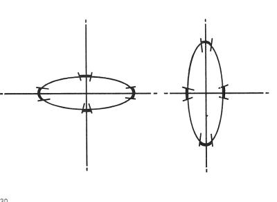
Fig 4.5: Regions where smaller VECTOR lengths are used.
- However, it should be noted that attempts to improve the
quality of the figure by reducing the vector length in this
way may be thwarted by the repeatability properties of the
plotter itself. Each vector drawn by the plotter will not quite
mate up with the end of the previous one, and this effect becomes
more marked the greater the vector density. Factors limiting the
repeatability performance of a plotter include the following:
- Any movement of the film caused by mechanical instabilities.
- Drifting of the electronics due to temperature and voltage variations.
- Distortion introduced by the optical system.
- Drifting of the optical system due to temperature variations.
- The positional accuracy of the cathode ray tube.
- ELLCUT
- The function of this subroutine is basically the solution of the two simultaneous equations describing the ellipse and straight line. These are:
- Ellipse: [(X - XCENT) / SEMMAJ]2 + [(Y - YCENT) / SEMMIN]2 = 1
- Line: (X - X1) / (X1 - X2) = (Y - Y1) / (Y1 - Y2)
- Elimination of either variable leaves a quadratic in the other to be solved. This method of solution to obtain the points of intersection of the line and ellipse was abandoned because the numbers involved quickly overflow the range of numbers permitted by the computer, and in any case the solution of a quadratic may involve the subtraction of quantities which, unless they can be specified with high precision, will result in errors in the answer.
- MAIN PROGRAM
- The major difficulty in writing the main program is to ensure that the coding written produces the required graphical output for all possible variations in co-ordinate positioning, and also that any peculiar situations that may occur through such a sequence are appreciated and allowed for in the program.
Hardware difficulties
The following points should be noted:
The system software produced by A.W.R.E. at Aldermaston causes each frame to be identified by a job number and date, and also to be numbered. This information appears as blobs down the right hand edge of the screen when the film is projected. Modifications to the software are in hand to remove this information.
On the Atlas 2 computer at Aldermaston a program will be rejected if it overruns the time allotted to it. The run time required to produce a given number of frames depends on the complexity of the output in terms of the mathematical calculation involved to produce each frame as well as the graphical complexity itself. With the film described in this report, 15 minutes maximum computer time was requested, and a maximum of 480 frames produced by each run. Also, although not used to produce the film, software facilities are available to repeat frames (up to a maximum of 31 times), without using up extra computer time. By repeating each frame say 4 times in this way it would be possible to obtain longer sequences without increasing the costs. This is normally the case with film used in a projector at several fps.
Again, although not used during the production of the film, software facilities are available for increasing the density of the lines. Thicker lines could also be obtained by repeating the lines slightly displaced, but this method will, of course, increase the computer time required to produce the figure.
With reference to the quality of the film images, S.F. Martin of Joseph Kaye and Company Inc., in a letter reproduced in the 1967 Year-end Report of the Computer Animation Committee of UAIDE, mentions the following experiences they have had whilst producing films on an SC4020, as part of their bureau operations.
The SC4020 camera is not a movie camera. They now use a modified 35 mm Bell and Howell studio camera.
Kodak 5498 RAR film is used because it gives denser lines without image spreading (i.e. higher contrast than other films).
High-contrast processing (development in a bath intended for positive prints) is used.
The brightness of the tube is measured and the camera adjusted before filming commences.
From these comments it is apparent that extra care must be taken to obtain good quality film when using an SC4020, or similar, for movie work (in contrast to normal microfilm work), and that the operators of the equipment must be made movie conscious to ensure consistently good quality results.
ECONOMICS
Mr J. Halas, of Halas & Batchelor Cartoon Films, has estimated that the manual cost per loop to generate such a film, using conventional techniques, would be about one half that of computer-production in this case. This figure would cover all hand drawing and photographic processes involved.
The cost of producing the pilot film described breaks down into salary, travel and computer time costs.
It has been estimated that two-thirds of the total costs incurred are of a development nature, and the cost of producing further films, similar in scope, size and detail to that described in this report, would be one third of the figure in this case, that is two-thirds of the manual costs.
There is little to be gained in terms of cost savings when animated films are produced by computer, but there are clearly savings when parts of an already written computer program can be used for further films - i.e. two or more films have features in common, or when it is extremely important to reduce lead time to a minimum - i.e. prepare a film as quickly as possible. The major saving in time is due to the short period between inputting a prepared program, and obtaining a film suitable for reduction and final issue. This is of the order of hours, rather than days or weeks, which is the case when films are produced manually.
FUTURE DEVELOPMENTS
As will be apparent from the foregoing, extensive knowledge of a high level language (in this case Fortran) is required before any film can be coded and produced. In addition, errors in the program can only be spotted by producing a film and then projecting it. This is a wasteful and time consuming process.
In an idealized system for future development the source statements would in all probability be written in a simplified form which includes details of the pictures required and also details of how any elements in these pictures are to move. The statements will take the form of near-English words, and the method of combining these words to produce the required animation could be learned by someone having no previous programming experience. This language would, in fact, resemble the high level languages developed for controlling numerically controlled machine tools.
Programs would be debugged on-line by viewing the film sequence on a cathode ray tube display/light-pen arrangement first of all. This would allow the animator/operator to make changes either to correct any errors, or to alter positions, increment sizes and timings etc., in an on-line mode. When satisfied with the animation sequence a (program) switch can be altered to divert the generalized output to the microfilm recorder post processor which will, in turn, drive the recorder to produce the finished film.
It is also hoped that recorders capable of exposing colour film will become generally available - one such recorder is believed to exist in the USA, and the Lockheed Company have made an interesting film showing the flutter of a large aeroplane airframe, using this recorder.
Possible future actions suggested by experience indicate that there is a need to co-ordinate school requirements in the UK, and proceed as in this instance. Or, alternatively, import the Bell system from the USA, which simplifies film production, or possibly to contract out the technical work involved to Bell Laboratories in the USA.
In each of the above cases further finance may well be required.
Fig 4.6: Flowchart of the main program.