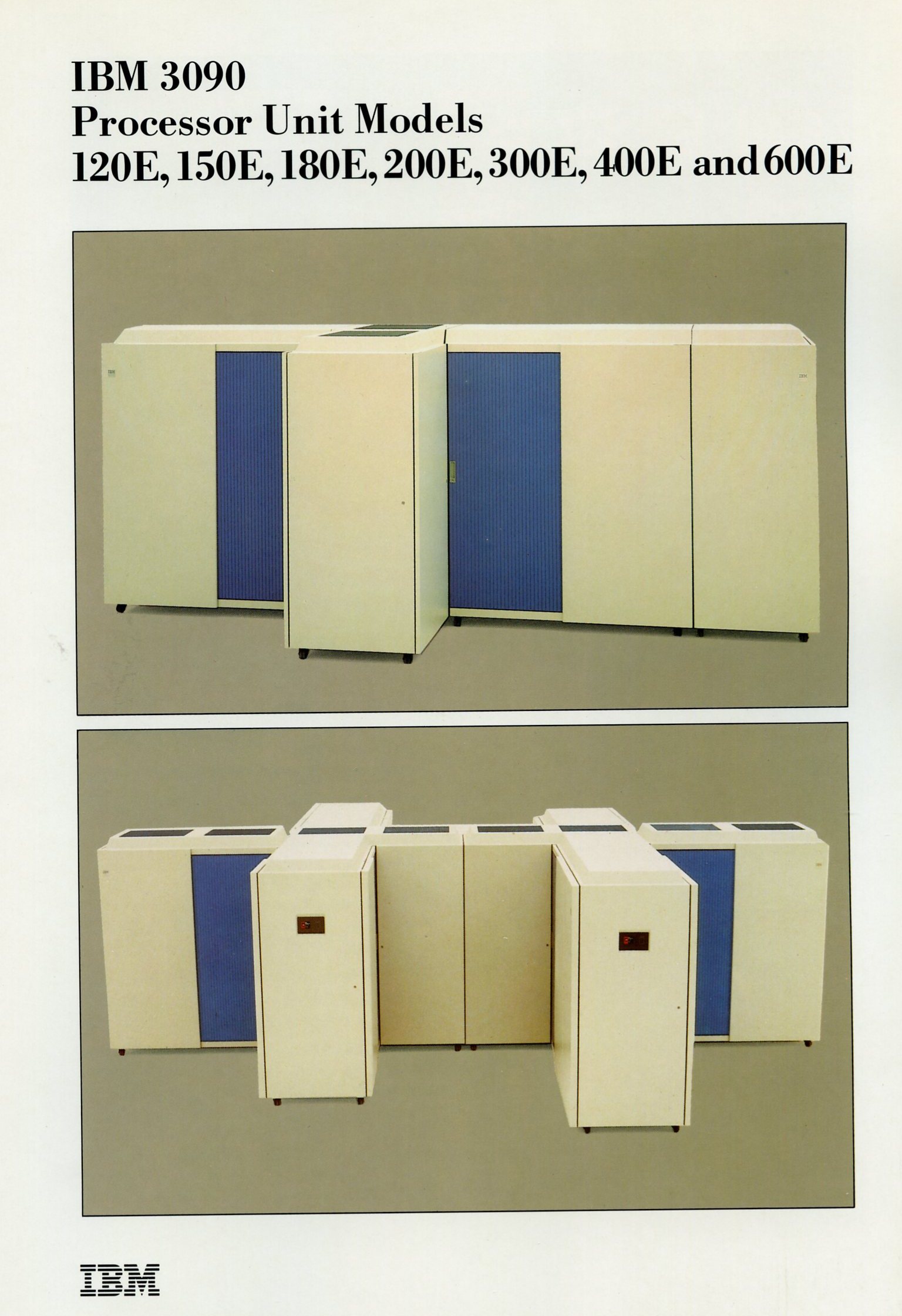
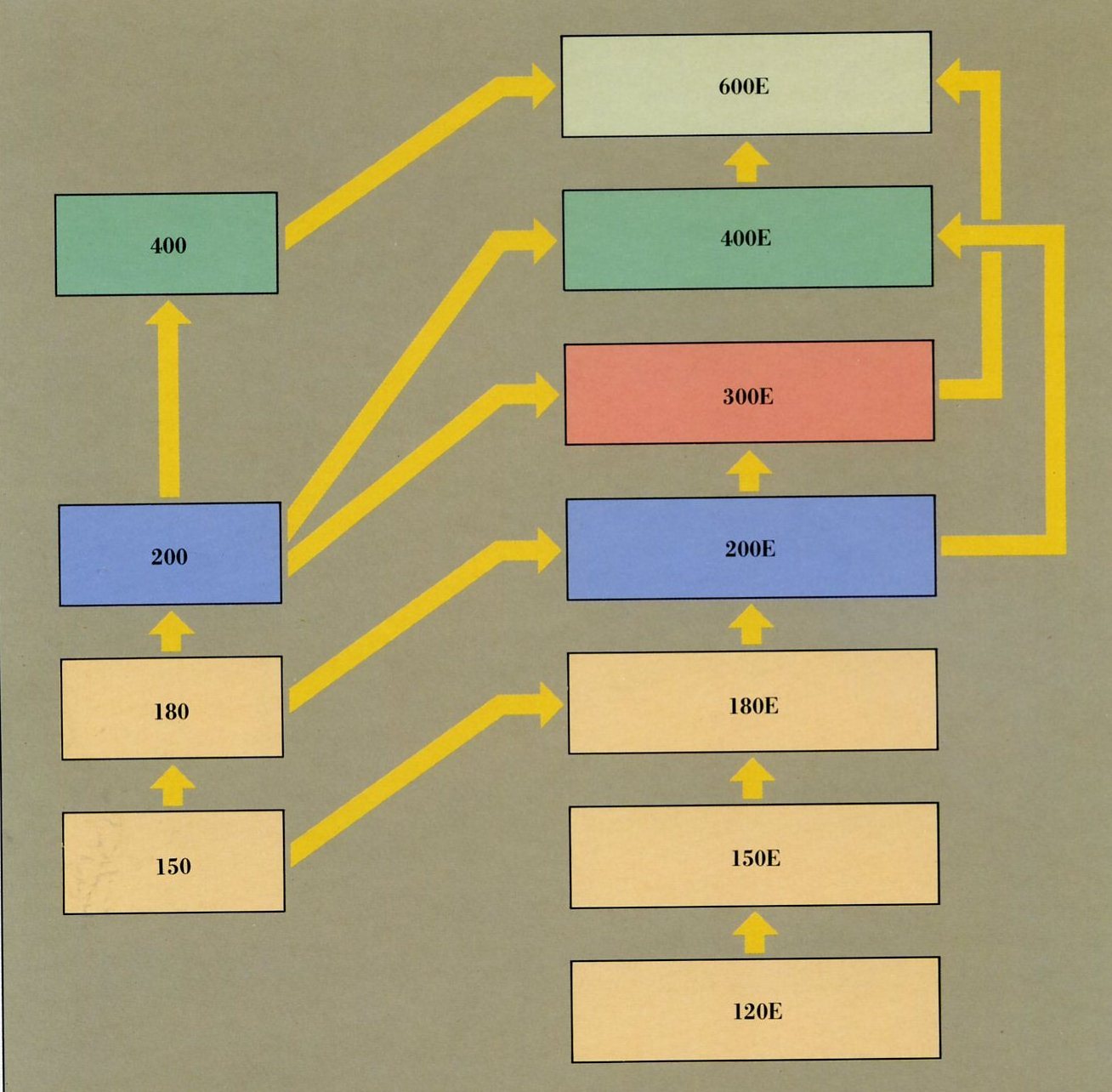
The IBM 3090 is a field-upgradeable family which
consists of seven models: three uniprocessors, one dyadic, one triadic, one four-way and one six-way multiprocessor.
They provide up to ten-fold growth from the smallest Model l20E to the largest Model 600E.
In addition, from one to six optional Vector Facilities (one per central processor) may be configured to provide enhanced
performance and modular growth for vectorisable applications.
An IBM 3090 can be installed in approximately 11 to 17 hours. Field upgrades can be made to the next higher model in
nine to 24 hours depending on the model.
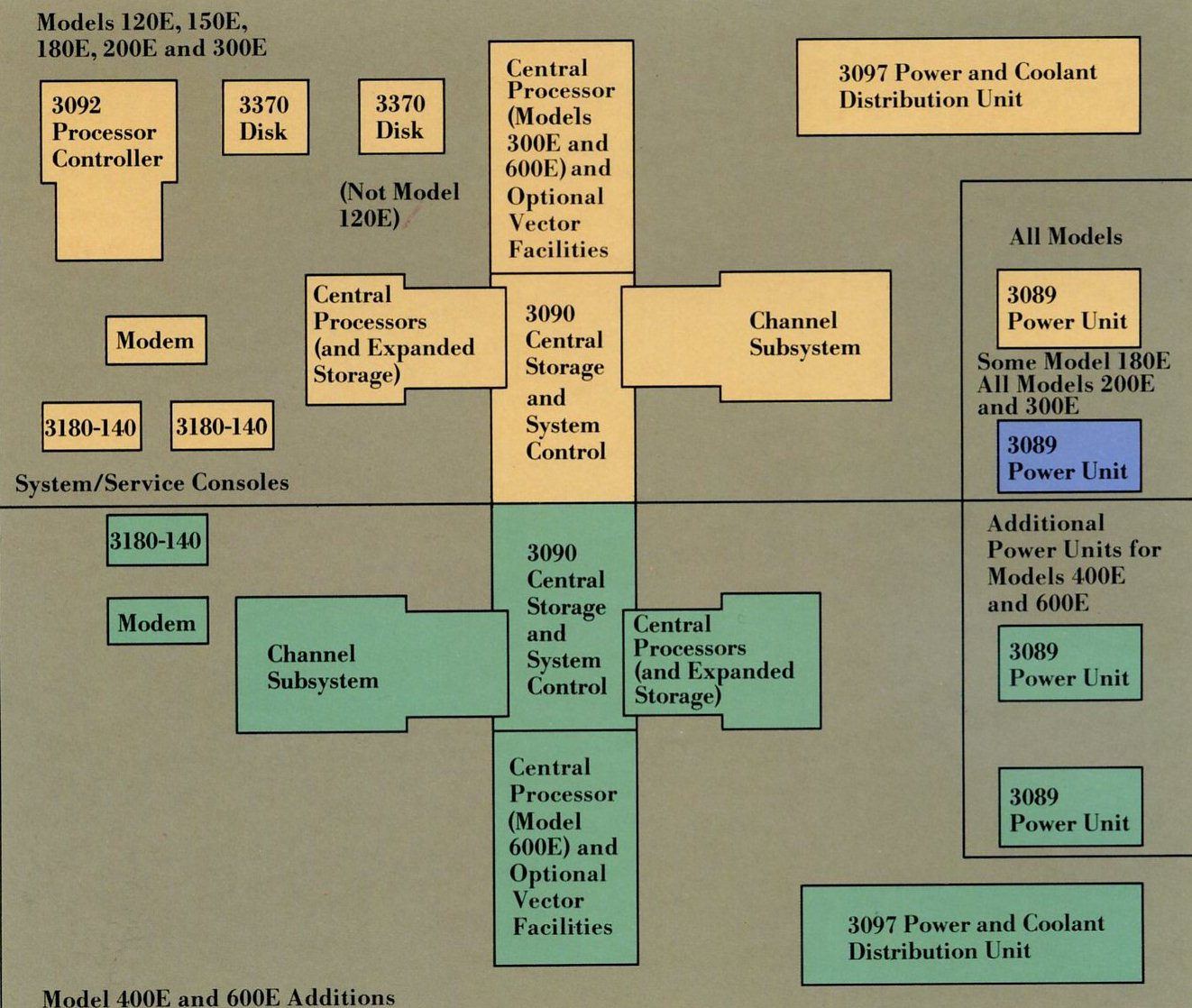
All IBM 3090 Processor Complexes include:
Two 3370 Model A2 Direct Access Storage
Devices (except Model 120E, which requires one 3370 Model A2 Direct Access Storage Device).
Two 3180 Model 140 Display Stations as system and service support consoles.
One 3864 Model 2 Modem or a 4800 bits per second (bps) switched network modem supporting an autocall/autoanswer feature.
One 3097 Model 1 or Model 2 Power and Coolant Distribution Unit.
An IBM 3090 Model 120E, 150E or 180E Complex, in addition to the common support units listed above, comprises:
One 3090 Uniprocessor Processor Unit with one central processor and one optional Vector Facility.
One or two 3089 Model 3 Power Units or equivalent 400 Hz power source. The second 3089 is only required if
192/256 Mb Expanded storage and a Vector Facility are configured.
One 3092 Model 1 Processor Controller (or one 3092 Model 3 for a 3090 Model l20E).
An IBM 3090 Model 200E or 300E Complex, in addition to the common support units listed above, comprises:
One 3090 Model 200E Processor Unit with two central processors and one or two optional Vector Facilities,
or one 3090 Model 300E Processor Unit with three central processors and one, two or
three optional Vector Facilities.
Two 3089 Model 3 Power Units or equivalent 400 Hz power source.
One 3092 Model 1 Processor Controller.
An IBM 3090 Model 400E or 600E Complex comprises:
One 3090 Model 400E Processor Unit with four central processors and up to four optional Vector Facilities,
or one 3090 Model 600E Processor Unit with six central processors and up to six optional
Vector Facilities.
Three 3180 Model 140 Display Stations as system and service support consoles.
Two 3864 Model 2 Modems or two 4800 bps switched network modems supporting an
autocall/autoanswer feature.
Two 3097 Power and Coolant Distribution Units.
Model 1s and Model 2s may be used in any combination.
Four 3089 Model 3 Power Units or equivalent 400 Hz power source.
One 3092 Model 2 Processor Controller.
IBM 3090 Processor Complex Support Units and Vector Facility:
For details on the IBM 3089, IBM 3092, IBM 3097 and other IBM 3090 Processor Complex Support Units, see the associated
publication G511-0134.
For additional details on the IBM 3090 Vector Facility and its System Software, see the associated publication GSll-0136.
The Processor Units of the IBM 3090 family perform the data processing functions of the IBM 3090
Processor Complex and are the most powerful computers available from IBM.
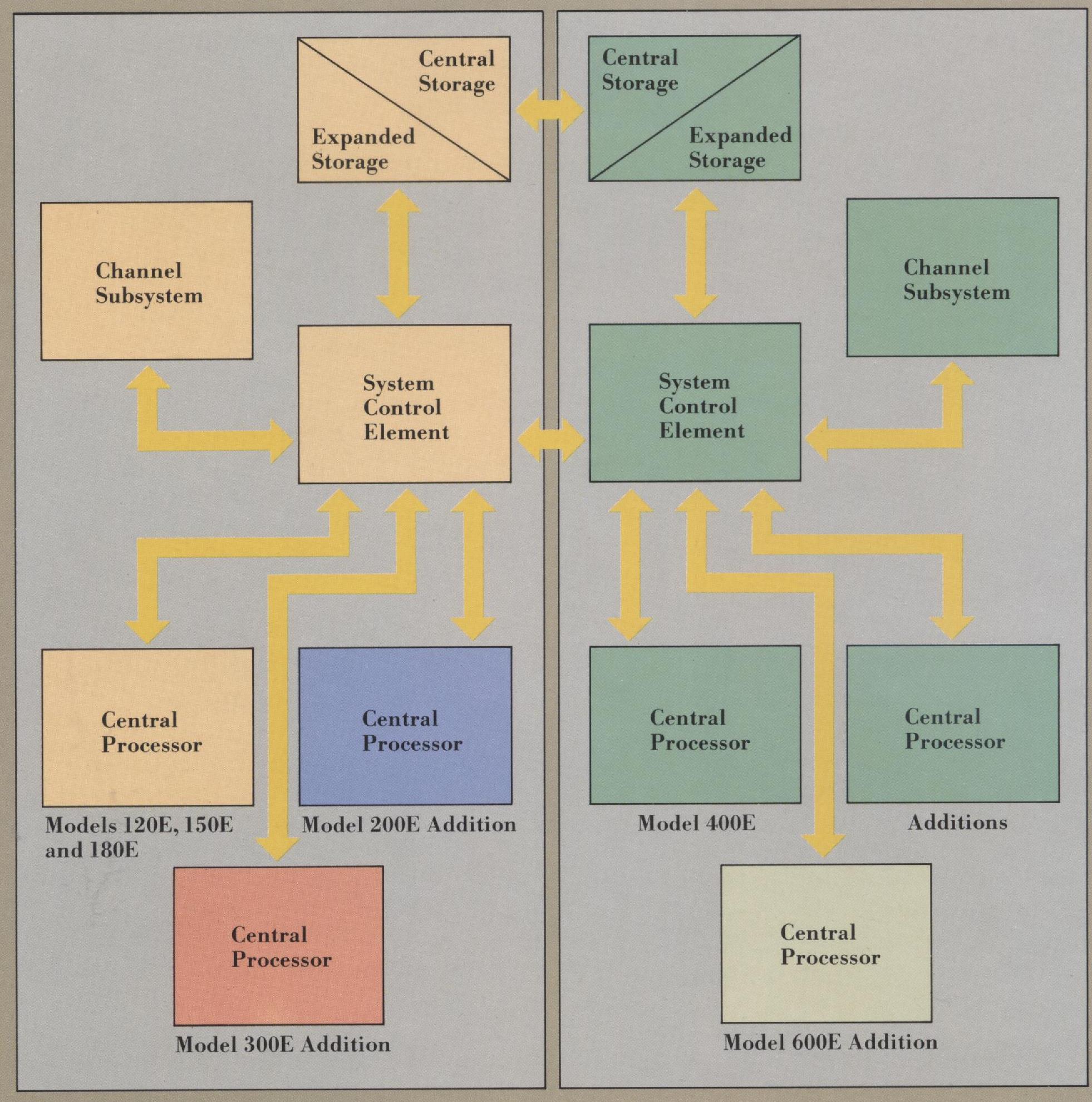
All IBM 3090 Processor Units are composed of four main elements:
Central Processor.
System Control Element.
Central and optional Expanded Storage.
Channel Subsystem.
The Model 120E, a new entry-level uniprocessor, has:
One Central Processor with 18.5 ns cycle time and
one optional Vector Facility.
One System Control Element.
Processor Storage consisting of 32 Mb of Central
Storage and 64 or 128 Mb of optional Expanded Storage.
One Channel Subsystem with 16 or 24 channels.
The Model 150E, a uniprocessor, has:
One Central Processor with 17.75 ns cycle time
and one optional Vector Facility.
One System Control Element.
Processor Storage consisting of 32 or 64 Mb of
Central Storage and 64 or 128 Mb of optional Expanded Storage.
One Channel Subsystem with 16 or 24 channels.
The Model 180E, a more powerful uniprocessor, has:
Central Processor with 17.2 ns cycle time and one optional Vector Facility.
One System Control Element.
Processor Storage consisting of 32 or 64 Mb of
Central Storage and 64, 128, 192 or 256 Mb of optional Expanded Storage.
One Channel Subsystem with 16, 24 or 32 channels.
The Model 200E, a dyadic processor, has:
Two Central Processors with 17.2 ns cycle time and one or two optional Vector Facilities.
One System Control Element.
Processor Storage consisting of 64 or 128 Mb of
Central Storage and 64, 128, 192, 256 or 512 Mb of optional Expanded Storage.
One Channel Subsystem with 32, 40, 48 or 64 channels.
It operates as a single logical system.
The Model 300E, a triadic processor, has:
Three Central Processors with 17.2 ns cycle time and up to three optional Vector Facilities.
One System Control Element.
Processor Storage consisting of 64 or 128 Mb of
Central Storage and 64, 128, 192, 256 or 512 Mb of optional Expanded Storage.
One Channel Subsystem with 32, 40, 48 or
64 Channels.
It operates as a single logical system.
The Model 400E, a four-way processor, has:
Four Central Processors with 17.2 ns cycle time
and up to four optional Vector Facilities.
Two linked System Control Elements.
Processor Storage containing a total of 128 or
256 Mb of Central Storage and 128,256,384,512 or 1024 Mb of optional Expanded Storage.
Two Channel Subsystems with a total of 64, 80, 96 or 128 channels.
It is divided into an A and a B side, each of which
contains two Central Processors and one of each
of the other elements, and can operate:
Either as a single logical system, with the A and B sides combined, in single image mode.
Or as two logical dyadic systems, with the A and B sides working independently, in partitioned mode.
The Model 600E, a six-way processor, has:
Six Central Processors with 17.2 ns cycle time and up to six optional Vector Facilities.
Two linked System Control Elements.
Processor Storage containing a total of 128 or
256 Mb of Central Storage and 128,256,384,512 or 1024 Mb of optional Expanded Storage.
Two Channel Subsystems with a total of 64, 80, 96 or 128 channels.
It is divided into an A and a B side, each of which contains three Central Processors and one of each of the other elements,
and can operate:
Either as a single logical system, with the A and B sides combined, in single image mode.
Or as two logical triadic systems, with the A and B sides working independently, in partitioned mode.
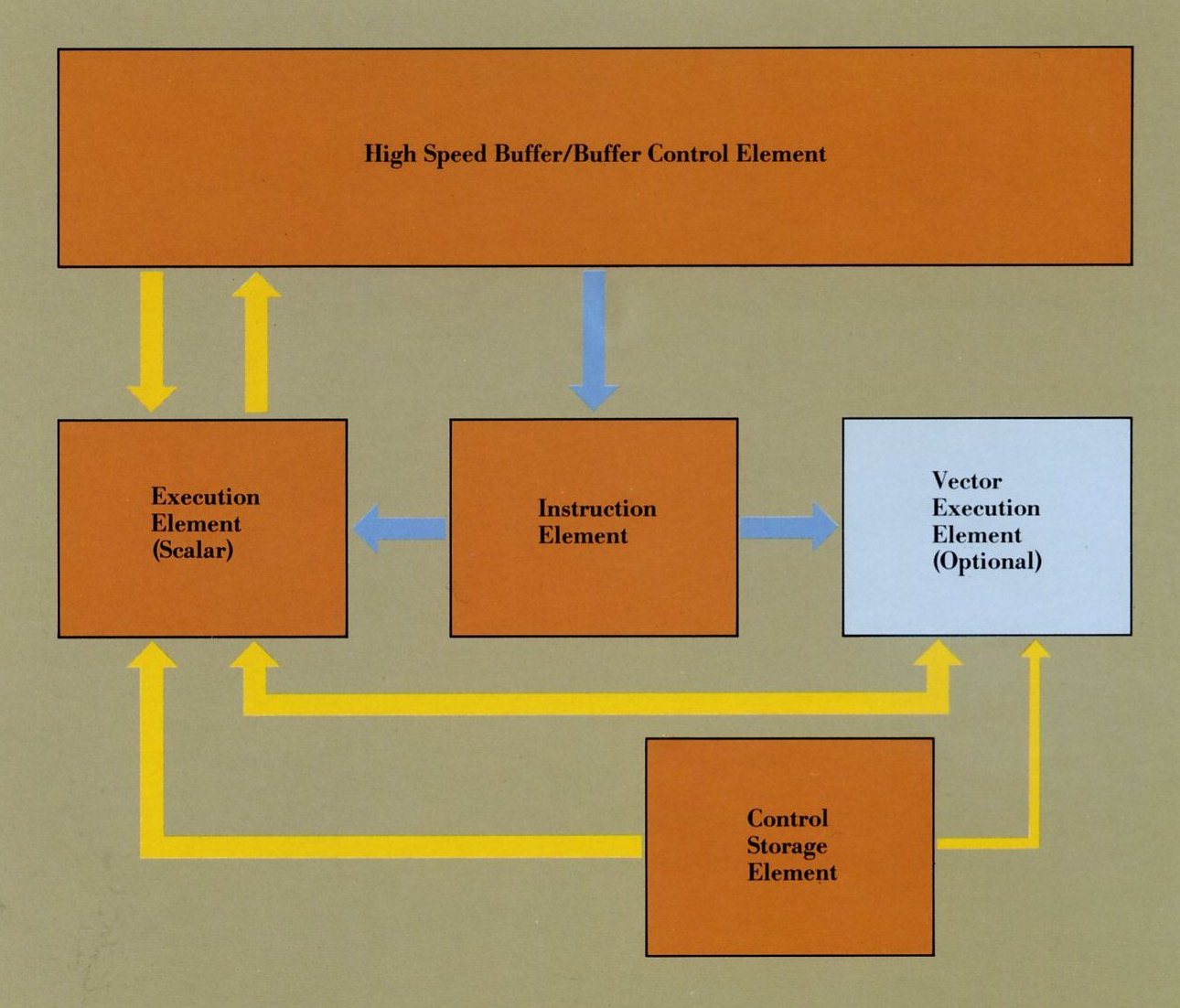
The IBM 3090 Processor Unit has a highly efficient three-level storage hierarchy consisting of High Speed Buffer,
Central Storage and optional Expanded Storage, managed by the System Control Element and Buffer Control Element.
System Control Element:
Contains logic for the control of data storage and retrieval for the processor complex.
Provides the communication path between Processor Storage and the rest of the processor complex.
Performs error checking and correction.
High Speed Buffer/Buffer Control Element:
Provides an individual storage access function for each Central Processor for active data and
instructions.
Contains a 64K-byte High Speed Buffer, Buffer Directory, Translation Look-aside Buffer (TLB) and
Dynamic Address Translation (DAT) hardware.
The High Speed Buffer is transparent to program that are being executed.
Central Storage:
Central Storage, using IBM-developed one megabit memory chips, is provided as follows:
32 Mb for the Model 120E.
32 or 64 Mb for the Models 150E and 180E.
64 or 128 Mb for the Models 200E or 300E.
128 or 256 Mb for the Models 400E or 600E.
Central Storage is shared by the Central Processors in the Models 200E or 300E and can be shared or partitioned
on the Models 400E or 600E.
Central Storage, and optional Expanded Storage, are linked via Processor Storage Control to the System Control Element
by a pair of 64-bit data paths.
All single hit errors are detected and corrected.
All double bit errors are detected and some are corrected.
Dynamic frame de-allocation permits page-frame with correctable double-bit errors to be deallocated
in 4K-byte blocks under system control program control.
Storage Protection provides Store and Fetch protection, preventing unauthorised access.
Optional Expanded Storage:
Expanded Storage provides optional low-cost, large-capacity solid state storage using IBM
developed one megabit chips:
64 or 128 Mb for the Models l20E and 150E.
64,128,192 or 256 Mb for the Model 180E.
64, 128, 192, 256 or 512 Mb for the Models 200E and 300E.
128, 256, 384, 512 or 1024 Mb for the Models 400E and 600E.
Transfer is exclusively to and from Central
Storage in 4K-byte pages performed by Processor Storage Control at system control program request.
On the Model 400E or 600E each Processor Storage Control can access the whole of Expanded Storage without
transferring data through the
second System Control Element.
Expanded Storage is transparent to user programs.
All single and double bit errors are corrected. All
triple bit errors are detected and some are corrected. Four bit errors in a single block are detected.
Expanded Storage reduces the paging and swapping load on channels and I/O devices and improves system response and performance.
17.2, 17.75 or 18.5 nanosecond cycle time for the enhanced models and 18.5 nanosecond cycle time for the previously available
models.
64K-byte High Speed Buffer for fast access to instructions and data.
Overlapped design permits Instruction Element to decode instructions in parallel with scalar or vector instruction execution.
The degree of overlap varies depending on the 3090 model.
Up to seven instructions can be in processed simultaneously in the Instruction and Execution
Units of each Central Processor.
Multi-engine design permits all of the Central Processors in the multiprocessing models to operate simultaneously.
Supports both System/370 and System/370 Extended Architecture:
System/370 Architecture permits up to 16Mb
virtual storage per address space.
System/370 Extended Architecture permits 2048 Mb virtual storage per address space and Bimodal Addressing for
co-existence of System/370 programs.
.
General purpose instruction set of 212 scalar instructions.
52 scalar floating point instructions.
Short (32-bit), long (64-bit) and extended
(128-bit) precision scalar floating point support.
16 general purpose registers (32 bits wide).
Four 64-bit floating point registers, which can be
paired for 128-bit operations.
Microcode assists for added performance:
Double capacity Control Storage Element on enhanced 3090 models stores instructions for microcoded operations and assists.
Start Interpretative Execution (SIE) improve performance for preferred guests running under VM/XA Systems Product (SP)
or VM/XA System Facility (SF):
MVS/XA performs at near native mode.
MVS/370 performs at 86-88% of native mode.
Virtual Machine Assist under SIE improves performance of VM/SP and VM/SP HPO guest by approximately 20%.
Preferred Machine Assist (PMA) enables
MVS/370 guests to run at approximately 95% of native speed under the VM/SP High Performance Option.
SORT assist improves performance of the DESORT program product.
Designed for outstanding scalar performance:
High speed multiply implemented in hardware.
Fast floating point add/subtract hardware.
Special loop control circuitry.
64-bit wide data paths.
Optional Vector Facility:
Provides significant performance improvement compared to scalar performance for typical vectorisable applications.
Executes vector arithmetic and logical operation on up to 128 sets of operands with a single instruction.
Pipelined design and compound instructions permit completion of up to two operations per cycle.
171 vector instructions allow arithmetic and logical operations with binary, short (32-bit) and long (64-bit) precision
floating point vectors.
16 vector registers can each store 128 32-bit elements and can be paired for 64-bit operations.
Three-address instruction formats minimise movement of information in registers and improve operand re-use.
Input operands may be:
Vector register and vector register
Vector register and storage
Vector register and scalar register
Storage and scalar register
Vector results are placed in vector registers, scalar results are placed in scalar registers.
Addressing can be performed using fixed stride values, indirect element selection or under mask control.
Automatic address updating handles sectioning of vectors longer than 128 elements.
Vector Activity Register, supported by the System
Measurement Facility (SMF), permits analysis of
vectorisation levels achieved.
Vector Affinity, supported by MVS/XA,
VM/XA SP, VM/XA SF and VM/SP HPO, ensures
that vectorised programs are run on a Central
Processor which has a Vector Facility.
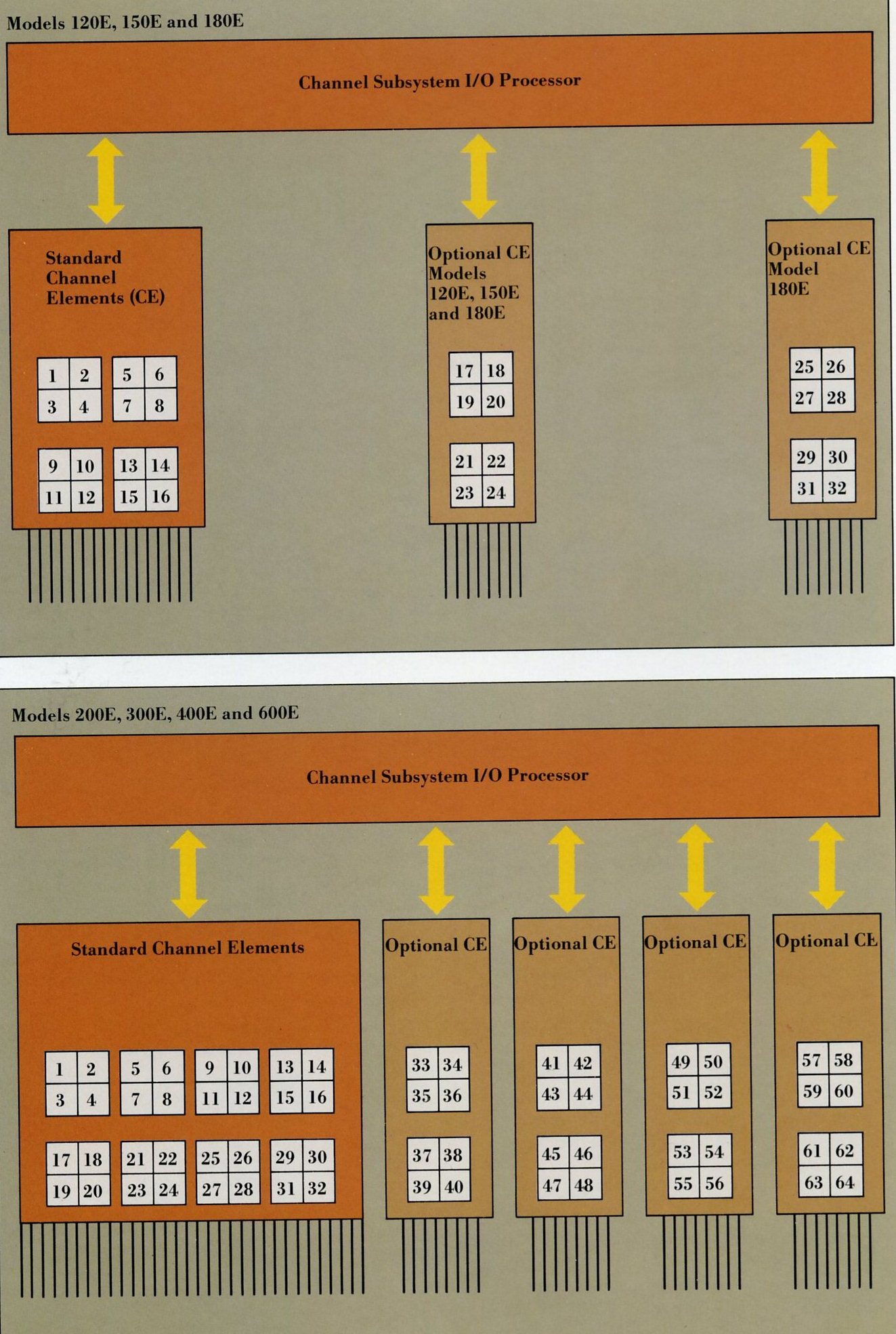
The Channel Subsystem performs I/O operation for the processor complex.
The Models l20E, 150E, 180E, 200E and 300E have one Channel Subsystem, the Models 400E and 600E have two Channel Subsystems.
Each Channel Subsystem contains an I/O Processor which communicates with its associated System Control Element
to access Central Storage and manages up to 16 Channel Elements.
Each Channel Element provides support for four channels. A separate microprocessor operates
each channel and can support up to eight control units.
All channels configured as block multiplexer channels can operate at 3 megabytes per second in data streaming mode
and at up to 1.5 megabyte per second in interlocked mode.
Both data streaming and non-data streaming devices may be attached to any block multiplexer channel on an intermixed basis.
Optionally, up to four channels per Channel Control Element can be initialised to operate as byte multiplexers. This permits:
up to four byte multiplexers for models 120E, l50E, 180E, 200E or 300E.
Up to eight byte multiplexers for models 400E or 600E.
System/370 Extended Architecture Mode Operation:
Any processor may initiate an operation with any I/O device and process any I/O interrupt using any channel path.
Up to four different logical paths to a single device may be used.
In single-image mode the two Channel Subsystems of a Model 400E or 600E co-ordinate activity and appear as one dynamic
Channel Subsystem to the system control program.
System/370 Mode Operation:
Channels may be grouped into logical channel
sets with one set assignable to a Central Processor.
MVS/370 supports a maximum of 16 channel per channel set.
VM/SP High Performance Option supports up to 32 channels per channel set.
Channel Set Switching permits a change of channel set assignment in the event of a Central Processor failure,
so that I/O access can be maintained.
Channel Configuration:
The Models 120E and 150E have 16 standard channels with one optional increment, giving a maximum of 24 channels.
The Model 180E has 16 standard channels with two optional increments, giving a maximum of 32 channels.
The Models 200E and 300E have 32 standard channels with three optional increments, giving a maximum of 64 channels.
The Models 400E and 600E have 64 standard channels with three optional increments, giving a maximum of 128 channels.
The channel, control unit and device configurations are defined to the Channel Subsystem by the I/O Configuration Dataset (IOCDS)
selected at system initialisation.
The IOCDS is created by the I/O Configuration Program and stored on the IBM 3370 Direct Access Storage Devices attached to
the IBM 3092 Processor Controller. Multiple IOCDSs which describe different I/O configurations may be stored.
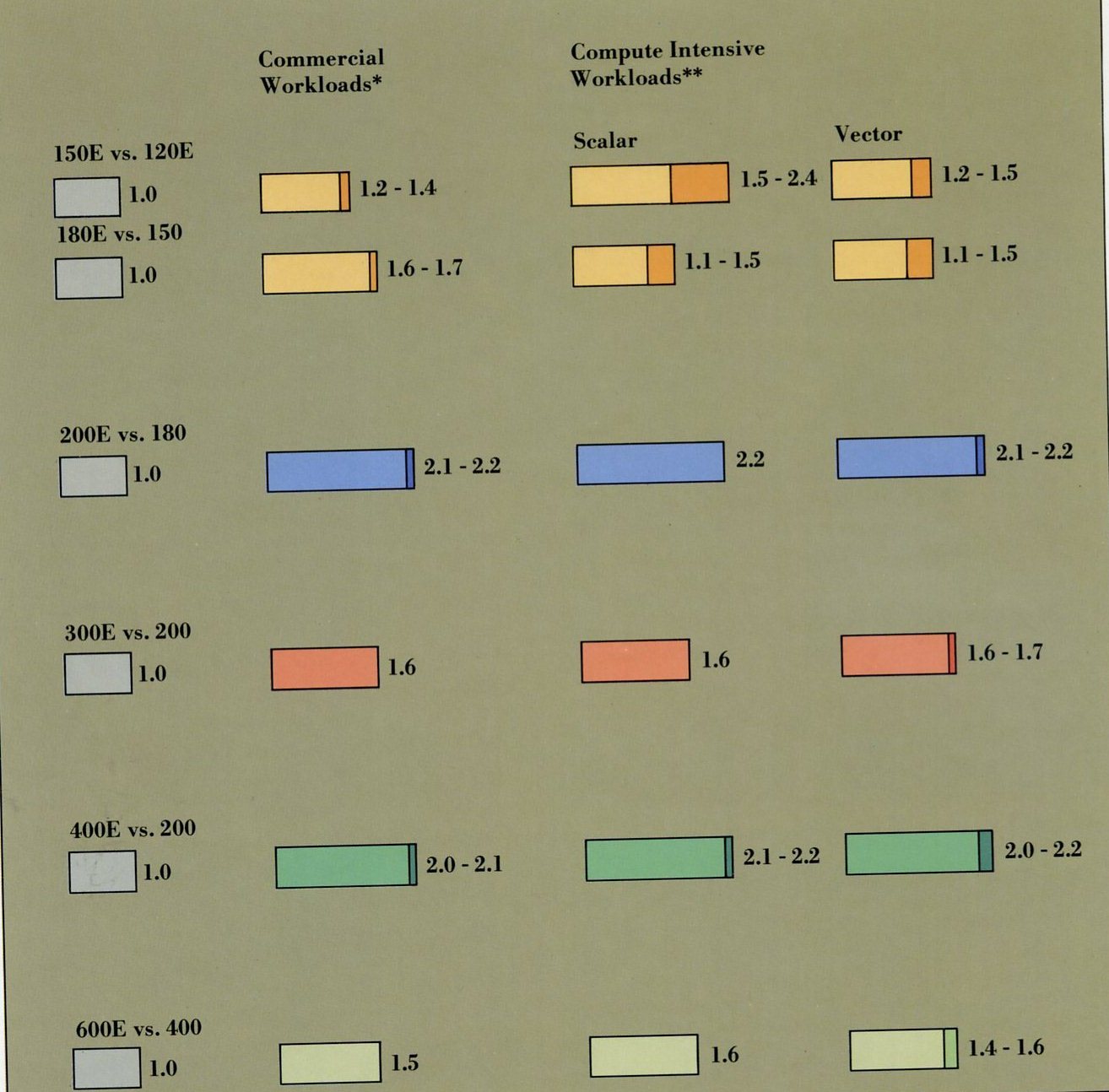
Performance gains in the enhanced IBM 3090 family are achieved by means of cycle time reductions,
technology improvements and design extensions.
The commercial comparisons for all models are Instruction Execution Rate Ratios (IERRs), while the comparisons for the compute
intensive applications are Internal Throughput Rate Ratio (ITRRs). An ITRR is the measurement of the central processor time of a job
on one system relative to the time on another system.
Additional details on 3090 scalar, vector and parallel performance for engineers, scientists and analysts may be found in the
companion publication CS11-0136.
Instruction Execution Enhancements:
The 3090 offers instruction sequencing controls
with an overlapped design to process instruction streams at the same time.
Most half-word instructions are processed in a single machine cycle on the 3090 models.
Some 3090 instructions are pre-executed to improve performance.
On the 3090's highly overlapped central processor, up to seven instructions can be in various stages of processing
at the same time.
Decode History Table and faster loop control on the 3090 contribute to reduce the delay associated with program branches,
providing overall improvement of 3090 performance.
Multiprocessor performance:
The 3090's System Control Element utilises buses that allow transfer both to and from requesters on any given cycle.
Most key data paths on the 3090 are parallel, which allows reading and writing to be done at the same time.
Floating Point Arithmetic Enhancements:
Improved multiply handling provides IBM's fastest multiply time ever.
Improved add/subtract handling provides IBM's fastest add/subtract time ever.
Special loop-handling circuitry speeds up loop execution.
64-bit machine design:
Data paths throughout the processor unit are 64 bits wide permitting movement of 64 bits of data or instructions per cycle.
Channels:
Reduced Instruction Set Computing (RISC) architecture is employed by the I/O Processor in the Channel Subsystem, providing
high performance, design flexibility and channel
subsystem extendability.
Each of up-to-128 channels available on the 3090 Model 600E has its own dedicated microprocessor.
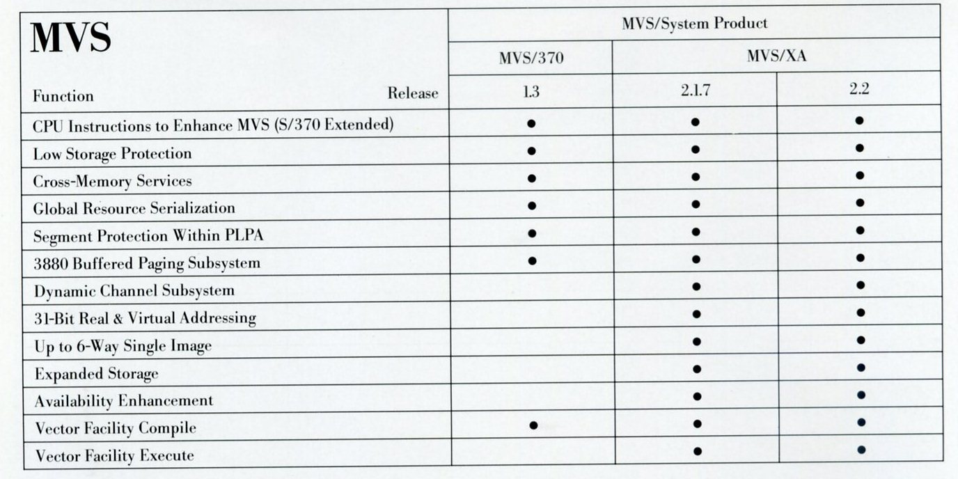
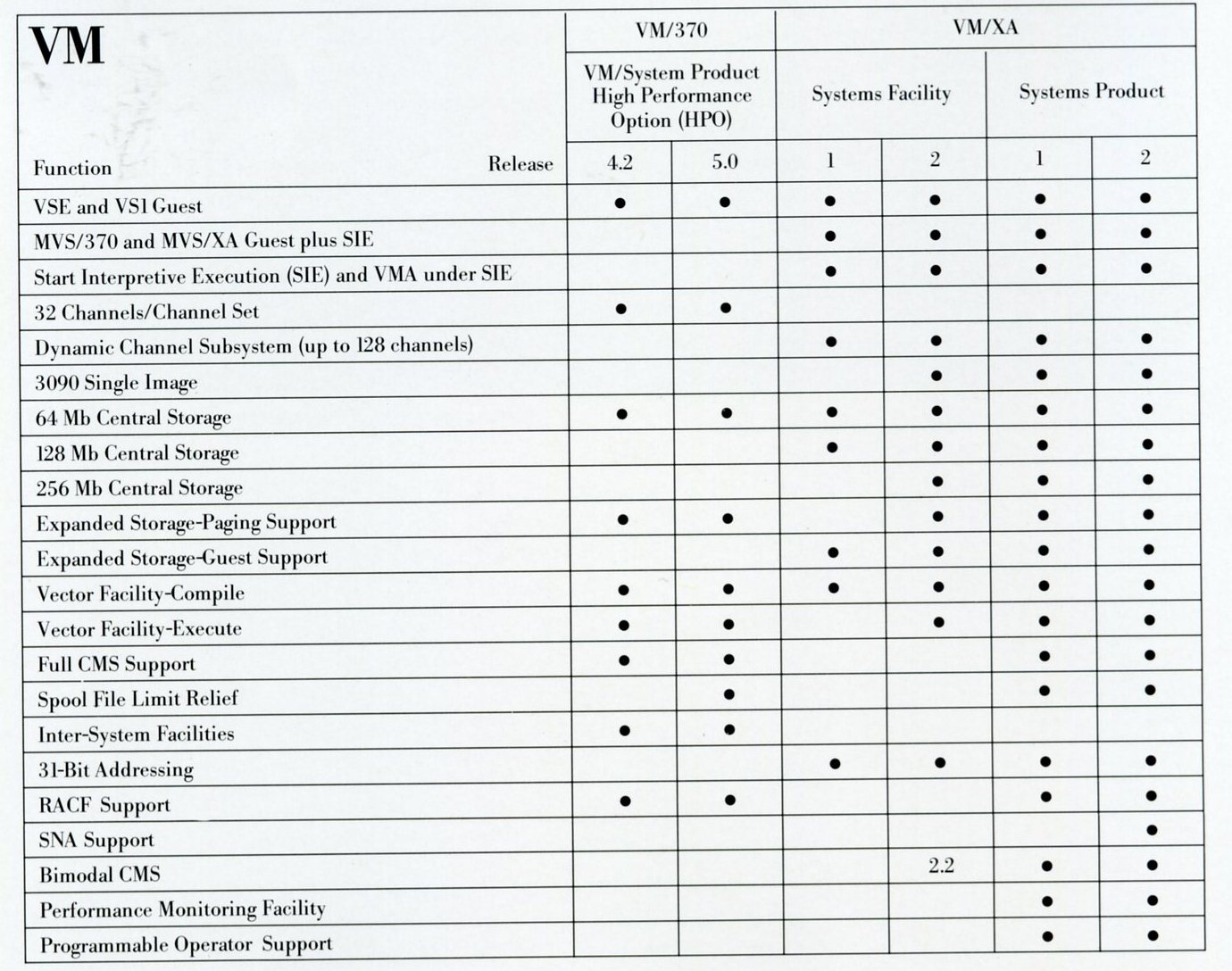
System Control Program Support
The IBM 3090 Family is supported in System/370 Extended Architecture mode by MVS/XA, VM/XA
Systems Product and VM/XA System Facility. In System/370 mode support is provided by MVS/370,
VM/SP High Performance Option and Airline Control Program/Transaction Processing Facility Version 2.2.
Details of the support available with recent releases of MVS and VM are given below: