A new FORTRAN contouring package is now available. There are two user level routines (CNTR2A,CNTR2B) for the production of contour maps of a surface for" which the heights are given at the points of a mesh. CNTR2A is used for contouring over a (possibly skewed) regular rectangular mesh. CNTR2B is used for contouring over a (possibly skewed) irregular rectangular mesh. Within each of the routines a number of options concerning the drawing of the map are available. These allow for a choice of two methods of contouring over the grid, user specified or routine calculated heights, specification of the angle between the axes of the grid, and various options concerning the layout of the map, labelling of the contours and distinctions between the contours. However, as these are available via a common block, the user need only specify those options he requires (if any) which are different from the default set. Only those items of data which are necessary' for a contour map are supplied, as arguments to the routines.
These routines are considerably more versatile than, the existing contouring routines in SMOG/SPROGS (which only handle regular square meshes of a restricted size - though it is possible to specify an internal boundary). In addition they are two to three times as fast.
CNTR2A and CNTR2B are in the new Graphics Algorithms library and are intended to replace the existing SMOG/SPROGS contouring routines (CNTOUR and CNTOR1) which will be removed from SMOG and SPROGS on 1 June, However, as CNTR2A and CNTR2B have no facility for specifying an internal boundary, the SMQG/5PRQGS contouring routine which has (CNTOR1) has been rewritten and is also in the library. (If there is sufficient demand for this type of routine then a routine CNTR2C, which would enable an internal boundary to be specified and all the options of the package to be used, may be produced.) For completeness, details and an example of the use of CNTOR1 are included as an appendix.
Unless stated otherwise the normal FORTRAN naming conventions for REAL end INTEGER variables apply.
CNTR2A (RMESH, UNUSED, ID, M, N, HEIGTS, NCONTS)
CNTR2B (RMESH, UNUSED, XPTS, YPTS, ID , M, N, HEIGTS ,NCONTS)
CNTR2A is the routine for producing a contour map of a surface for which the heights are given on a regular grid (the points are assumed to be one unit apart in the x and y directions starting at (0.0,0.0)). CNTR2B is the routine for producing a contour map of a surface for which the heights are given on an irregular grid (this is specified by means of the arrays XPTS and YPTS). It is assumed that if an irregular grid is being used then the points are closest together where most detail is needed and farthest apart where least detail is needed. Hence, for both CNTR2A and CNTR2B, each mesh rectangle is treated the same by the internal contouring routines and the x and y coordinates are only used to calculate the points to be plotted. A brief description of the method used by each of the internal contouring routines is given, in Section 1.4.
The arguments, of the routines are defined as follows:
RMESH is a two-dimensional REAL array of size (ID,N) which contains the heights at the grid points. These are arranged so that the first dimension increases as y increases and the second dimension increases as x increases.
UNUSED is a two-dimensional LOGICAL array of the same size as RMESH which is used by the routine as workspace.
XPTS,YPTS (CNTR2B only) are one-dimensional REAL arrays of size N and M respectively and contain the distances of successive points along each axis from the bottom left-hand corner of the grid ie XPTS(1)=YPTS(1)=0.0. If XPTS(1) or YPTS(1) is not zero then it will be treated as an additional offset from the origin but any skewing will then be about the point (OX,OY) and not the corner of the grid (normally these points are coincident).
ID is the size of the first dimension of RMESH. This is necessary in case M and N are read in. (As arrays must be declared explicitly in FORTRAN, this is needed for the subroutine to use the correct elements of RMESH if only part of the array is used. Usually ID and; M will be the same.)
M,N are- the number of points in the y and x directions respectively.
HEIGTS is a one-dimensional REAL array of size NCONTS and contains the contour heights if they are specified or is used to store, them if they are calculated (this is the default option).
NCONTS is the number of contour heights.
CNTKEY(X, Y , HEIGTS, N1 , N2)
CNTKEY is the routine for plotting a key to the contour heights (the contours are only labelled with the contour number) and is normally called after the call to CNTR2A or CNTR2B. The key is plotted within a rectangle (not drawn) of size 22 x character width by X2-N1+8) x line space where line space is 5/3 x character height. The character height and width are set by CNSIZE in CNTR2A or CNTR2B (see RCH in Section 1.3) but may be altered before the call to CNTKEY if desired.
The arguments of the routine are defined as follows:
X,Y are the x,y coordinates of the top left-hand corner of the exscribed rectangle described above.
HEIGTS is a one-dimensional REAL array containing the contour heights and should be the same array specified in the call to the contouring routine.
N1,N2 are the numbers of the first and last contours to be included in the key. (Several keys may be plotted to include all the. contours.) No check is made by the routine to see if the key will fit within the current visible area.
COMMON/CNTOPT/ICON, ICH, OX, OY, RCOS, IBOX, IGR, ILAB, RFR, RCH, IT, IDF, RLV
Various options concerning the production of the contour map are available as outlined in the introduction. These are specified by assigning values to the thirteen variables in a named COMMON block, (CNTOPT). Default values are assigned to these variables by means of a BLOCK DATA segment so that values only need be assigned to those variables corresponding to an option, for which a value other than the default is required.
The options and corresponding variables are outlined below:
| VARIABLE | OPTIONS AVAILABLE | DEFAULT VALUE |
|---|---|---|
| ICON | Internal contouring. routine CNTRH1 (ICON=1) or CNTRH2 (ICON=2) is used - see Section 1.4 | 2 |
| ICH | Contour heights are. specified in array HEIGTS (ICH=1) or calculated by the routine (ICH=0) | 0 |
| OX,OY | Offset of the origin of the grid from the origin of the user's coordinates | 0.0,0.0 |
| RCOS | Cosine of the angle (between1 0 and 180 degrees) between the two axes of the grid (ie the skew of the grid) | 0.0 |
| IBOX | Frame drawn round map (IBOX=1> or not (IBOX=0) | 1 |
| IGR | Grid points plotted (IGR=1) or not (IGR=0) | 0 |
| ILAB | Contours are labelled: none (ILAB=0), every one (ILAB=1) every Ith one (ILAB=I) | 1 |
| RFR | Frequency of labelling on contours (labels appear every ICON*RFR*MAX(M,N) steps, with a minimum of one label per contour unless ILAB=0. One label per contour is achieved with RFR set to a very large value or zero. | 1.0 |
| RCH | Height of characters used for labelling - height is RCH*M/80 (CNTR2A) or RCH*(YPTS(M)-YPTS(1))/80 (CNTR2B) | 1.0 |
| IT | Contours drawn thicker (the number of hits is trebled so this has its best effect for a low number of hits originally): values as for ILA | 0 |
| IDF | Differentiate between contours above and below a certain level (IDF=1) or not (IDF=0). Contours below level are drawn as broken lines (this has its best effect on larger grids) | 0 |
| RLV | Is the-level associated, with IDF | 0.0 |
CNTRH1,CNTRH2
These routines are not callable by the user but are described here briefly to enable him to choose which he requires to be called (see ICON in Section 1.3). They are slightly modified versions of those of B R Heap (NPL).
In both routines the basic method is to take each contour height in turn and trace any contours of this height through the mesh. In CNTRH1 inverse linear interpolation is used to find the points where the contour crosses the mesh lines and these points are joined by straight lines. Any ambiguity as to which way a contour turns is solved by assuming high ground on the right. In CNTRH2 the surface height at the centre of each mesh square is approximated by the average of the heights at the four corners. In addition to the points where the contour crosses the mesh lines (as in CNTRH1), points where the. contours cross the mesh diagonals are found using inverse linear interpolation. These points are again joined by straight lines. This technique, which effectively produces a triangular mesh, avoids any ambiguity as to which way a contour turns.
On the 360/195 if the CNTOPT COMMON block is required it must be included explicitly in a user program.
Heap B R, 'Two FORTRAN Contouring Routines' NPL Report NAG47 April 1974.
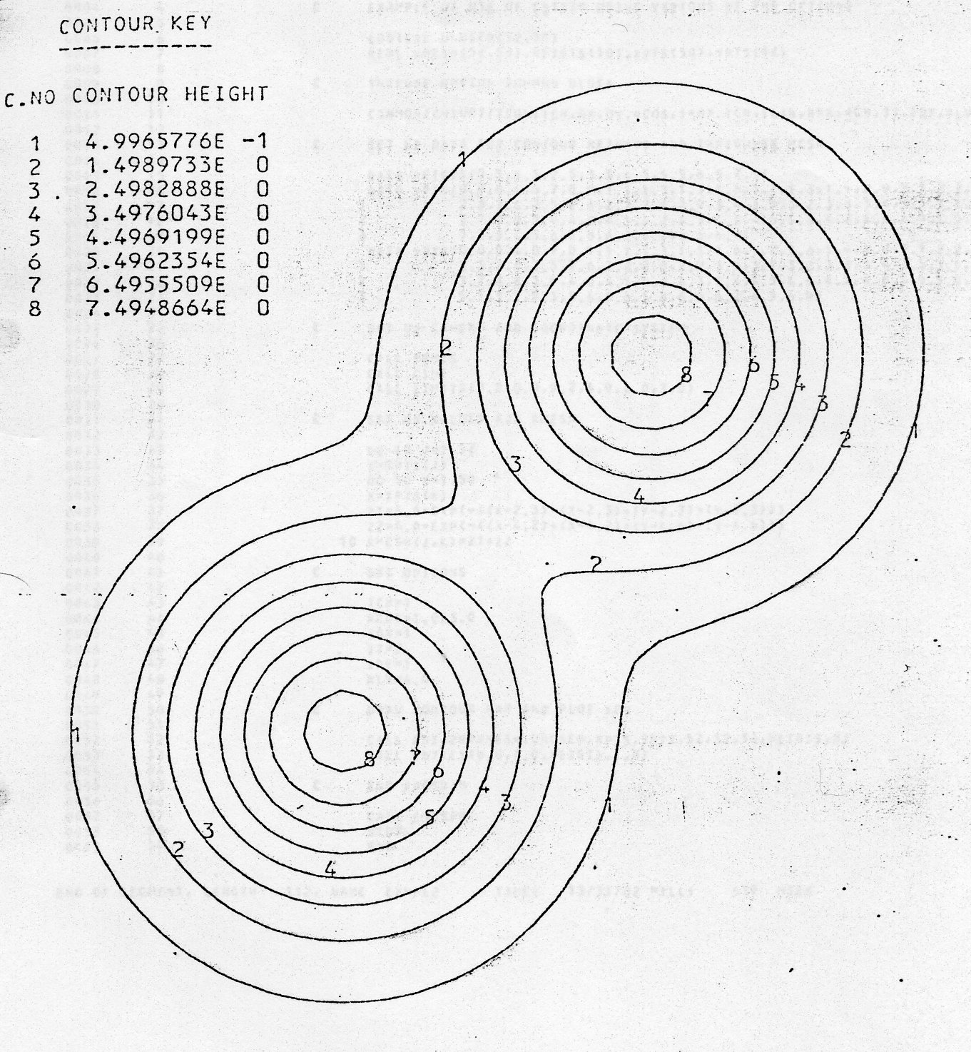
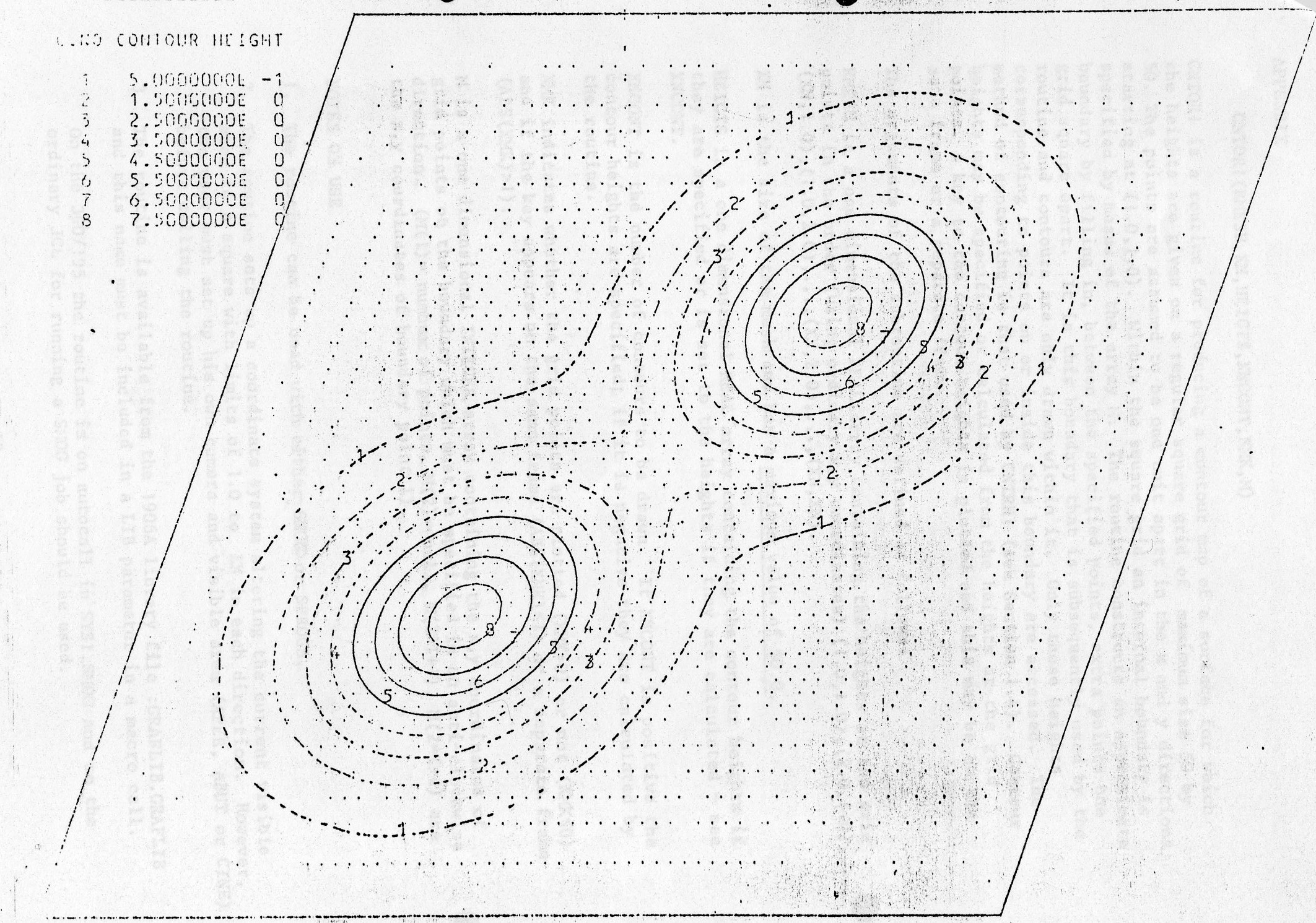
The two examples below illustrate the use of the two routines. In example 1 CNTR2A is used with all the default options. In example 2 CNTR2B is used with a selection of the options.
If the program of example 1 is in a file EXAMPLE 1 then the following SMOG call can be used to run: it on the 1906A
SMOG *CR EXAMPLE1,LIB. :GRAFLIB.GRAFLIB,JT25
The lineprinter and FR80 output from the two examples are shown.
On the 360/195 the ordinary JCL for running a SMOG job should be used to run the examples. (Note that the LIST and MASTER statements are 1906A specific and irrelevant: to- the. 360/195).
      LIST
      MASTER EXMPL1
C     EXAMPLE OF USE OF CNTR2A USING ALL THE DEFAULT OPTIONS
      LOGICAL UNUSED(50,50)
      REAL RMESH(50,50),HEIGTS(10)
C     SET UP CAMERA AND COORDINATE SYSTEM
      CALL FRHCS
      CALL CINE
      CALL LIMITS(0.0.0.0,49.0,49.0,1.0,1.0)
C     SET UP VALUES FOR MESH
      DO 10 J=1,50
      Y=0.14*J-0.1
      DO 10 K=1,50
      X=0.14*K-0.1
      Z1=8.0*EXP(-((X-2.3)*(X-2.3)+(Y-2.3)*(Y-2.3)))
      Z2=8.0*EXP(-((X-4.2)*(X-4.2)+(Y-4.6)*(Y-4.6)))
   10 RMESH(J,K)=Z1*Z2
C     DRAW CONTOUR MAP AND PLOT KEY
      CALL CNTR2A(RMESH,UNUSED,50.50,50,HEIGTS,8)
      CALL CNTKEY(0.0,49.0,HEIGTS,1,8)
C     END  PROGRAM
      CALL ENDSPR
      STOP
      END
--------------------------------------------------------
SUBROUTINE CNTR2A HAS BEEN ENTERED
==================================
THE VALUES OF THE VARIABLES IN THE OPTION COMMON BLOCK HAVE BEEN CHECKED
THE VALUES ARE :-
OPTION              VALUE
 ICON                 2
 ICH                  0
 OX              0.0000000E 00
 OY              0.0000000E 00
 RCOS            0.0000000E 00
 IBOX                 1
 IGR                  0
 ILAB                 1
 RFR             0.1000000E 01
 RCH             0.1000000E 01
 IT                   0
 IDF                  0
 RLV             0.0000000E 00

 THE CONTOURS DRAWN ARE :-
 CONTOUR NO     CONTOUR HEIGHT     NO DRAWN
     1          0.4996578E 00        1
     2          0.1498973E 01        1
     3          0.2498289E 01        2
     4          0.3497604E 01        2
     5          0.4496920E 01        2
     6          0.5496235E 01        2
     7          0.6495551E 01        2
     8          0.7494866E 01        2
      LIST
      MASTER EXMPL2
C     EXAMPLE OF USE OF CNTR2A USING VARIOUS OF THE OPTIONS
      LOGICAL UNUSED(50,50)
      REAL RMESH(52,50),HEIGTS(10),XPTS(50),YPTS(52)
C     INCLUDE OPTION COMMON BLOCK
      COMMON/CNTOPT/ICON, ICH, OX, OY, RCOS, IBOX, IGR, ILAB, RFR, RCH, IT, IDF, RLV
C     SET UP DATA FOR CONTOUR HEIGHTS AND IRREGULAR MESH
      DATA HEIGTS/0.5,1.5,2.5,3.5,4.5,5.5,6.5,7.5/
      DATA XPTS/0.0,0.4,0.7,0.9,1.1,1.3,1.5,1.6,1.7,1.8,1.9,2.0,2.1,2.2,
     1          2.3,2.4,2.5,2.6,2.7,2.8,2.9,3.0,3.1,3.2,3.3,3.4,3.5,3.6,
     2          3.7,3.8,3.9,4.0,4.1,4.2,4.3,4.4,4.5,4.6,4.7,4.8,4.9,5.0,
     3          5.2,5.4,5.6,5.8,6.0,6.2,6.5,6.9/
      DATA YPTS/0.0,0.4,0.7,0.9,1.1,1.3,1.5,1.6,1.7,1.8,1.9,2.0,2.1,2.2,
     1          2.3,2.4,2.5,2.6,2.7,2.8,2.9,3.0,3.1,3.2,3.3,3.4,3.5,3.6,
     2          3.7,3.8,3.9,4.0,4.1,4.2,4.3,4.4,4.5,4.6,4.7,4.8,4.9,5.0,
     3          5.1,5.2,5.3,5.4,5.6,5.8,6.0,6.2,6.5,6.9/
C     SET UP CAMERA AND COORDINATE SYSTEM
      CALL FRHCS
      CALL CINE
      CALL LIMITS(0.0.0.0,9.2,6.9,4.0,3.0)
C     SET UP VALUES FOR MESH
      DO 10 J=1,52
      Y=YPTS(J)
      DO 10 K=1,50
      X=XPTS(K)
      Z1=8.0*EXP(-((X-2.3)*(X-2.3)+(Y-2.3)*(Y-2.3)))
      Z2=8.0*EXP(-((X-4.2)*(X-4.2)+(Y-4.6)*(Y-4.6)))
   10 RMESH(J,K)=Z1*Z2
C     SET OPTIONS
      ICH=1
      RCOS=1.0/3.0
      IGR=1
      IT=2IDF=1
      RLV=4.0
C     DRAW CONTOUR MAP AND PLOT KEY
      CALL CNTR2B(RMESH,UNUSED,XPTS,YPTS,52.52,50,HEIGTS,8)
      CALL CNTKEY(0.0,7.0,HEIGTS,1,8)
C     END   PROGRAM
      CALL ENDSPR
      STOP
      END
--------------------------------------------------------
SUBROUTINE CNTR2B HAS BEEN ENTERED
==================================
THE VALUES OF THE VARIABLES IN THE OPTION COMMON BLOCK HAVE BEEN CHECKED
THE VALUES ARE :-
OPTION              VALUE
 ICON                 2
 ICH                  1
 OX              0.0000000E 00
 OY              0.0000000E 00
 RCOS            0.3333333E 00
 IBOX                 1
 IGR                  1
 ILAB                 1
 RFR             0.1000000E 01
 RCH             0.1000000E 01
 IT                   2
 IDF                  1
 RLV             0.4000000E 01

 THE CONTOURS DRAWN ARE :-
 CONTOUR NO     CONTOUR HEIGHT     NO DRAWN
     1          0.5000000E 00        1
     2          0.1500000E 01        1
     3          0.2500000E 01        2
     4          0.3500000E 01        2
     5          0.4500000E 01        2
     6          0.5500000E 01        2
     7          0.6500000E 01        2
     8          0.7500000E 01        2
CNTOR1(RMESH, XN, HEIGT, XNCONT, XMK, M)
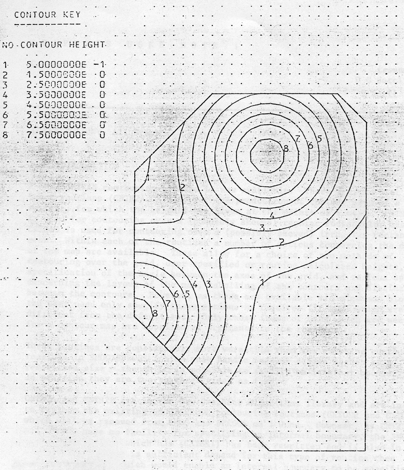
CNTOR1 is a routine for producing a contour map of a surface for which the heights are given on a regular square grid of maximum size 50 by 50. The points are assumed to be one unit apart in the x and y directions starting at (1.0,1.0). Within the square grid an internal boundary is specified by means of the array M. The routine constructs an approximate boundary by filling in, between the specified points, extra points one grid square apart. It is this boundary that is subsequently used by the routine and contours are only drawn within it. Only those heights corresponding to points on or inside this boundary are accessed. The method of contouring is that used by CNTRH1 (see Section 1.4). Contour heights may be specified or calculated from the heights at the grid points. A key to the. contour heights is plotted and this may be on the same frame or a separate frame.
The arguments of the subroutine are defined as follows:
RMESH is a one dimensional REAL array containing, the heights at the grid points in the order (using ordinary x,y coordinates) (1.0,1.0), (2.0,1.0),.., (XN,1.0),(1.0,2.0),...(XN,2.0),...(XN,YN).
XN is the size of the mesh, and. has a maximum, value of 50.0.
HEIGTS is a one dimensional REAL array, containing, the contour heights if they are specified or is set to the heights if they are calculated - see XNCONT.
XNCONT is the number of contours to be drawn. If XNCONT is positive the contour heights are specified; if it is negative they are calculated by the routine.
XMK indicates whether the grid points are plotted (XMK>0) or not (XMK≤0) and if the key appears on the same frame (ABS(XMK)≤1) or a separate frame (ABS(XMK)>1).
M is a one dimensional INTEGER array containing the x,y coordinates of grid points on the boundary which must be specified in an anti-clockwise direction. (M(1) = number of points, M(2)= null, M(2*I+1) , M(2*I+2) are the x,y coordinates of boundary point I).
BDRY, TMPLT, MAINCO, CP1, DRWBDY, CONTHT, ANDLOG, QRITE, FLCONT, REDUND, ARK, CNTKEY
The example below illustrates the use of the routine. If the program is in a file EXAMPLE then the following SMOG call can be used to run it on the 1906A
SMOG *CR EXAMPLE,LIB :GRAFLIB.CRAFLIB,JT25
The lineprinter and FR80 output from the example are shown. Note that if the LIB parameter is omitted the old version of this routine; will be used; (until 1 June) which will produce different output.
On the 360/155 the ordinary JCL for running a SMOG job should be used to run the example. (Note that the LIST and. MASTER statements are 1906A specific and irrelevant to the 360/195.)
      LIST
      MASTER   EXMPLE
C     EXAMPLE   Of    USE   OF    CNTOR1
      INTEGFR   M(12)
      REAL RMESH(2500),Heights(10)
C     SET UP DATA FOR BOUNDARY AND CONTOUR HEIGHTS
      DATA M/5,0,31,3,41,3,41,37,25,40,17,17/
      DATA HEIGTS/0.5,1.5,2.5,3.5,4.5,5.5,6.5,7.5/
C     SET UP CAMERA AND VISIBLE AREA
      CALL FRNCS
      CALLCINE
C     SET UP VALUES FOR MESH
      DO 10 J=1,50
      Y=0.14*J-0.1
      DO 10 K=1,50
      X=0.14*K-0.1
      Z1=8.0*EXP(-((X-2.3)*(X-2.3)+(Y-2.3)*(Y-2.3)))
      Z2=8.0*EXP(-((X-4.2)*(X-4.2)+(Y-4.6)*(Y-4.6)))
   10 RMESH(L)=Z1*Z2
C     DRAW CONTOUR MAP
      CALL CNTOR1(HMESH,50.0,HEIGTS,8.0,1.0,M)
C     END PROGRAM
      CALL ENDSPRE
      STOP
      END
SUBROUTINE CNTOR1 HAS BEEN ENTERED
==================================
 THE CONTOURS DRAWN ARE :-
 CONTOUR NO     CONTOUR HEIGHT     NO DRAWN
     1          0.5000000E 00        2
     2          0.1500000E 01        2
     3          0.2500000E 01        2
     4          0.3500000E 01        2
     5          0.4500000E 01        2
     6          0.5500000E 01        2
     7          0.6500000E 01        2
     8          0.7500000E 01        2