
Two computers that marked the early days of computing on the Harwell site are:
Early on at Harwell, most calculations were done with desk calculating machines, both manual and electric. These were followed by a succession of card based accounting/calculating machines.
The 555 Electronic Calculator was at the top of the Hollerith range and the first delivery to a customer was around 1957. It had a drum which could hold 105 registers and a large double plugboard which could hold up to 150 program steps The exterior of the drum was wound with steel wire.
From correspondence between Cecil Ramsbottom and Jack Howlett.
In its early years the Atomic Research Establishment at Harwell employed a number of operators using desk calculators to perform its computation. As the work load increased, a computer was sought to release the operators from the tedium of their task, so that their skills could be better employed on more interesting projects.
The computer was designed and built at the Establishment. Initial studies indicated that reliability was far more important than speed, and after considering the possibility of using valves or relays as storage elements, the arithmetic circuits were designed around the Dekatron cold cathode counting tubes made by Ericssons at Nottingham. At that time dekatrons were widely used in decimal counting circuits, and especially so in counters used by radio-chemists. They were also used by the Post Office in the random number generator known as Ernie to select the lucky numbers of the then recently introduced Premium Bonds.
The organisational, control and switching circuits were designed around conventional Post Office 3000 type relays. In some situations, up to twenty four changeover contacts were operated simultaneously, with the benefit of complete isolation between input and all output circuits, these features made the power of the logic very high, and when it first went into operation in 1951, this computer was almost unique in its ability to perform the four rules of arithmetic automatically from a single instruction without the use of subroutines. Six paper tape readers, as used for transmitting teleprinter data, accepted arithmetic instructions, which were obeyed as soon as they were read and parity confirmed, or numerical data for transfer to the dekatron storage units for processing. Results of computations were normally printed on to a teleprinter modified for five wire operation, or a reperforator which produced paper tape suitable for re-entry and further processing.
All the arithmetic functions were, in operation, the electrical equivalent of the mechanisms used in hand operated mechanical calculators, which had two registers and an accumulator to receive sums and products, and to which dividends were transferred before division. In the computer, any two store locations which were not in the same tens address group, could function as the registers, each store consisted of nine dekatrons, the first indicated the sign And the rest the eight digits of its content, the decimal point always followed the first digit. Originally twenty stores were fitted, this was soon increased to forty and then to eighty. Each store was addressed by a two digit number between 10 and 99. The accumulator operated exactly as its mechanical equivalent but was of double length, first half being addressed 09 and the later digits 08.
The dekatron had ten cathodes, and the cathode glow normally rests on one of these, indicating the number which it stores, indeed A unique virtue of this computer was that every digit in store could be read directly through the perspex panels. Between the cathodes were two sets of guide electrodes to which paired pulses were applied to move the cathode glow to a different digit. To transfer a number from a store, ten pairs of pulses were applied to the guides, driving the glow round the complete circle of cathodes; if for example the glow stood at digit 4, six pulse pairs representing the complement against ten, would take it forward to cathode 0, And another four returning it to its origin. On passing cathode 0 a gas-filled trigger valve struck and changed the bins conditions of a double triode which had trains of ten pulses fed to its common cathode, thus one anode provided pulses representing the tens complement And the other the number in store. All digits in a store were transferred in parallel and the receiving store cathodes were connected to further trigger valves to transfer the carry digits in sequence After the original train of ten pulses.
During multiplication the multiplicand was added into any store and then successively added into the accumulator, whilst the multiplier was counted down to zero by successive subtractions of one unit, commencing at the most significant digit, decimal shifts being provided between each digit in turn.
Subtraction was performed by adding the complement of each digit against nine, this was achieved by reducing one of the trains of ten guide pulses to nine, and caused a carry digit to be sent from the sign digit to the least significant place. This meant that zero could be represented in two ways, one positive and the other negative. A series of subtractions were made to perform division, these started at the most significant digit and were repeated until the accumulator changed sign, at this point the divisor was added back once before the shift relays operated and the sequence continued.
A notable feature of the Dekatron Computer was the instructions code which everyone liked because it was so easy to remember. Each order consisted of five digits, the first denoted the operation And the last four the addresses of the sending and receiving stores, other non-arithmetic orders commencing with 0 gave comprehensive control over the source of instructions, decimal shifts and print layout.
In operation, addition and subtraction took about one second to complete each instruction, multiplication about five seconds and division up to eight. The various functions produced distinctive rhythmic chatter in the relay sets, and given a little practice, the progress of a programme could be easily judged by ear.
The Dekatron Computer gave faithful service at Harwell, and for those days had an excellent maintenance record, but because of the pace of computer development, which accelerated with the development of semiconductor devices, it was replaced in 1956. It was offered as a gift to an educational establishment, and forty institutions completed the application forms which required submissions stating how the computer might be used if awarded to them. The Wolverhampton and Staffordshire College of Technology was finally selected from a short list of nine.
It was collected from Harwell and delivered to the College by a local furniture remover. Re-assembly in a demonstration room with direct access to a small lecture theatre took a week, but it was another month before it was considered to be in a ready state to run a programme. The first attempt to square 1.3 occupied four mathematicians for two hours before the teleprinter eventually thumped out 1.69.
For convenience it was renamed Witch, an acronym for Wolverhampton Instrument for Teaching Computation from Harwell, but also appropriate because of its relative age and temperament. It was officially inaugurated in December 1957 at an open day for sixth form students in local schools who continued to come to the College and use it, full time degree and diploma students frequently used it for their projects, but the greatest demand came from Colleges of Education, and two day courses from them were run almost every week for many years, as the catchment area had a radius of almost a hundred miles.
Several calculations were made for local industry, which had provided funds for the project, most of the tasks were not difficult but reflected the experience at Harwell, as special tables were often provided for use in situations which otherwise required tedious calculation. Perhaps the most interesting of these involved the preparations of lists of combinations for making safe keys, the only alternative method is to write them in order within the limits of half a dozen restrictions.
During its first years at Wolverhampton, a few modifications were made, not only did these facilitate its use, but they also enabled the circuitry to be better understood. The most important of these was the installation of the spare bank of ten stores, so that the maximum capacity of ninety addresses could be used. Indicators were added to the sign examination circuits and the relay sequence modified to enable manual control to be regained, where previously a programme had gone beyond recall.
By 1974 Witch was the senior and perhaps the most respected of the three computers at the new Wolverhampton Polytechnic, but now students were able to work out problems on the electronic calculators which they carried in their pockets, moreover it was imporant that they should learn how to manipulate computer languages. Reluctantly it was decided that it should be retired in full working order.
Witch was still working until the day that it was dismantled and installed in the Birmingham Museum of Science and Industry as their only operational computer. After enquiries in Europe and America it was discovered that no other computer had been in continuous use for so long, and it was proclaimed by the Guinness Book Of Records as the most durable computer in the World.
The Dekatron was the third computer built in the UK (construction began in 1947) and was only the 17th computer in the UK when it was retired to Wolverhampton in 1957.
Bacon, R.C, and Pollard J.R. An Electronic digital computer. Electronic Engineering; 1950, Vol.22p.173.
Barnes R.C.M, Cooke-Yarborough E.H. and Thomas D.D.A. An Electronic digital computer, Electronic Engineering, 1951 Vol 23 pp. 286, 341.
The Harwell Computer. E.H. Cooke-Yarborough. Proceedings of Symposium, Automatic Digital Computation, N.P.L. March 1953.
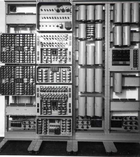
The Harwell Computer (Fig. 1) differs very markedly from other automatic computers designed up to the present. It may be of interest, therefore, first to relate the reasons for adopting this unorthodox design, and then to show In what ways the design has influenced the use of the computer.
In 1950 the Harwell Computing Group were finding that an increasing amount of their work involved much computation of a simple but repetitive nature. Such work performed on a desk calculator is extremely tedious for the operator and there is a real danger of errors arising from sheer boredom. Moreover such computations divert computing effort from other work which would make better use of the flexibility and adaptability of the human Intellect. Accordingly the Harwell Electronics Division began to consider the possibility of designing an automatic computer to do this work.
Only a small amount of effort could be assigned to the development and construction of a computer, so the design had to be made simple and had to use well established techniques where possible.
It appeared that a high-speed computer was not essential, since much time would in any case be spent in feeding data into and out of the machine. What was needed was something which would plough steadily and relentlessly through the mass of data presented to it. An all-relay computer was first considered, since adequate speed seemed attainable and experience with quite complex relay apparatus at Harwell had shown reliability to be excellent. Moreover, a multi-contact relay is an almost ideal component for circuit switching in a slow computer; Indeed, designers of fast computers must often wish for a high-speed circuit element as convenient and adaptable. Relays are however far less convenient when used as storage elements, and in existing all-relay computers it is necessary to use a very large number of relays to make up the quite modest amount of quick-access storage provided in these machines. Consequently it was decided to use relays only for switching and, after examination of other possibilities, dekatrons (ref. 1) were chosen for the quick access storage, since these were already coming into wide use in scaling circuits at Harwell and their properties were well known and seemed to offer many advantages. For example, each dekatron can store one decimal digit, thus doing the work of at least four storage relays with a power consumption of less than 100 mW. The associated electronic circuits can be relatively simple, since a dekatron delivers a pulse large enough to be used directly in arithmetical circuits without amplification, while the power required to register information in a dekatron is conveniently small. Several other convenient features of the dekatron emerged as the design proceeded.
It is not proposed here to discuss the detailed circuit design of the computer which has been fully described elsewhere (ref. 2). The design philosophy was that circuit simplicity and reliability were all-important, speed being a secondary consideration.
It was soon found that a decimal machine presented difficulties and complexities of a logical, not a circuit nature, which might not have been encountered in designing a binary machine. After some time had been spent in investigating the principles involved in long multiplication and division, a pilot machine was built, using three decimal digits plus the sign, to help resolve these problems.
The information thus obtained greatly facilitated design and construction of the full-scale machine which worked for the first time in April, 1951, Just over a year after the commencement of the project. Within a few weeks It was performing simple but useful computations connected with particle size data. A good deal of work remained to be done on the circuits and wiring, so, although the machine performed increasing amounts of useful computation during this period, it was not finally handed over to the Computing Group until May 1952.
The machine obtains its instructions and numerical data from standard 5-hole teleprinter tape. There are seven mechanical tape-readers; some of these usually carry repetitive routines in the form of closed loops of tape. Results are printed by a modified teleprinter. A two address code is used and each arithmetical instruction contains two pairs of decimal digits identifying the two addresses involved, preceded by a digit defining the operation to be performed. The reading of each instruction takes about a second and its execution takes a further second if the operation is a simple one; multiplication or division take ten to fifteen seconds. The speed is thus comparable to that of a normal desk machine. The computer handles numbers between +10 and -10 containing eight decimal digits; negative numbers appear as complements. There are 40 quick-access storage locations using dekatrons (with provision for adding a further 50) and a double length dekatron accumulator. The machine is designed for unattended running, so there is a comprehensive system for electrically checking the correct functioning of the circuits. Arithmetical checks are usually included in the programme to detect the small proportion of errors which may elude the functional checks. When the machine is set for unattended operation the occurrence of an error or other difficulties causes the machine to recommence the computation, to go back a few steps in the computation or to start the next problem. if the machine falls three times without completing the current computation it shuts down. If, however, after one or two failures it successfully completes the computation it begins the next computation with all its "lives" returned. This arrangement has been found very valuable in preventing the computer being shut down- by a trivial fault.
A slow computer can only justify its existence if it is capable of running for long periods unattended and if the time spent performing useful computations is a large proportion of the total time available. There appear to be as many ways of assessing computer serviceability as there are computers. The method used here is to take the number of hours the computer runs out of the possible maximum of 168 hours in a week. This therefore gives the total computing time plus the time spent on fault finding or maintenance with the computer switched on. The latter time seldom exceeds four hours per week and is usually much less, so it does not very significantly affect the results.
Over the period May 1952 to February 1953 the computer averaged 80 hours a week running time. This includes one week when the machine was serviceable but no programme was available and four weeks when the machine was out of action following an accident which caused severe mechanical damage. If these five weeks are excluded the average weekly running time becomes 92½ hours or 55% of the possible maximum. Most of the lost time was due to the machine failing during unattended running and having to wait until the next working morning for the fault to be corrected.
A further way to assess serviceability is to consider on what proportion of occasions when the machine was left to run overnight it worked until the following morning (15 hours later). This has been the case on 56% of the occasions. The corresponding figure for working over the weekend (63 hours) is 33%.
These percentages exclude occasions on which failure was due to errors in setting up the machine or in preparing the programme; they also exclude the occasions when the machine successfully completed the computation before the end of the period. On many of the occasions when the machine failed, the computation had reached a useful stage before failure occurred, so that the night's work was by no means wasted.
Most of the failures tend to be of a fleeting, intermittent nature, so one fault in the computer may cause several failures before it is detected. Faults in the relays and in the gas-filled cold cathode tubes have been commendably few. Most of the faults have been due to more conventional components, such as thermionic valves, metal rectifiers etc. Clearly there is room for improvement. It is hoped that this will be achieved by replacement of components prone to failure and by arranging for regular preventive maintenance.
Even at present, however, serviceability is sufficient to make the machine a powerful computing tool. Few, if any, other computers show comparable serviceability reckoned on the same basis, especially as maintenance of the Harwell computer represents only a small part of the work of one man.
The Harwell computer provides almost all the facilities of a large computer except high speed, so programming is in principle very similar. In practice, however, many of the subroutines and procedures used with fast machines become excessively time-consuming and alternative methods are used whenever possible.
The main difficulty arises in reading instructions or data from the paper tape in an order which cannot be predicted when the tape is prepared. This situation arises, for example, if the tape contains a table of functions or a rather complex subroutine containing many conditional instructions. Under these conditions the machine has to search along the loop of tape for the desired address. Computation is interrupted until this address is found, so if a long search is necessary much time may be lost. Numerous long searches also tend to reduce the life of the tape.
The need for long searches is minimized by splitting subroutines into as many small loops as possible to make best use of the available tape-readers. A consequence of this is that it is difficult to prepare economical subroutines which are flexible enough to be used in many different computations.
When the computer was first put into service it had only 20 dekatron stores and this made programming very difficult. The increase of the number of dekatron stores to 40 has almost completely removed this difficulty and shortage of quick-access stores is now seldom an embarrassment. Of course, if there were enough of these stores to accommodate long subroutines or tables of functions, the difficulties mentioned in the preceding paragraphs would disappear. The cost, however, would be prohibitive, because, unlike magnetic drum storage, the cost of Dekatron storage is almost directly proportional to the storage capacity provided.
Experience has shown that certain changes would simplify the programming or speed up the computation without adding much complication. While the changes could easily be included in a new machine they have not been incorporated in the present one as it is considered that extensive modification of an existing machine of this type would cause permanent deterioration of reliability.
The changes are indicated below.
Although of relatively simple design and low speed, the Harwell Computer has shown itself capable of performing a very useful amount of computation, because it can run for long periods unattended.
The combination of dekatrons, relays and teleprinter apparatus has been found very suitable for a computer of this size and speed. Modern dekatrons are capable of much higher speeds, but their use would add little to the speed of this type of computer. To exploit their increased speed successfully, very different methods of switching and storage would be necessary. Such a computer would undoubtedly be very useful, but it is perhaps questionable whether it could be constructed, run and maintained with as little technical effort as is needed by the Harwell computer.
1. BACON, P. C. and POLLARD, J. R. An electronic digital computer. Electron. Engng. 1950, 22, 173.
2. BARNES, R. C. M. , COOKE-YARBOROUGH, E. H. and THOMAS, D. G. A. An electronic digital computer. Electron. Engng, 1951, 23, 286, 341.
Jim Hailstone's paper: The Use of the Hollerith Type 555 Electronic Calculator for scientific calculation.
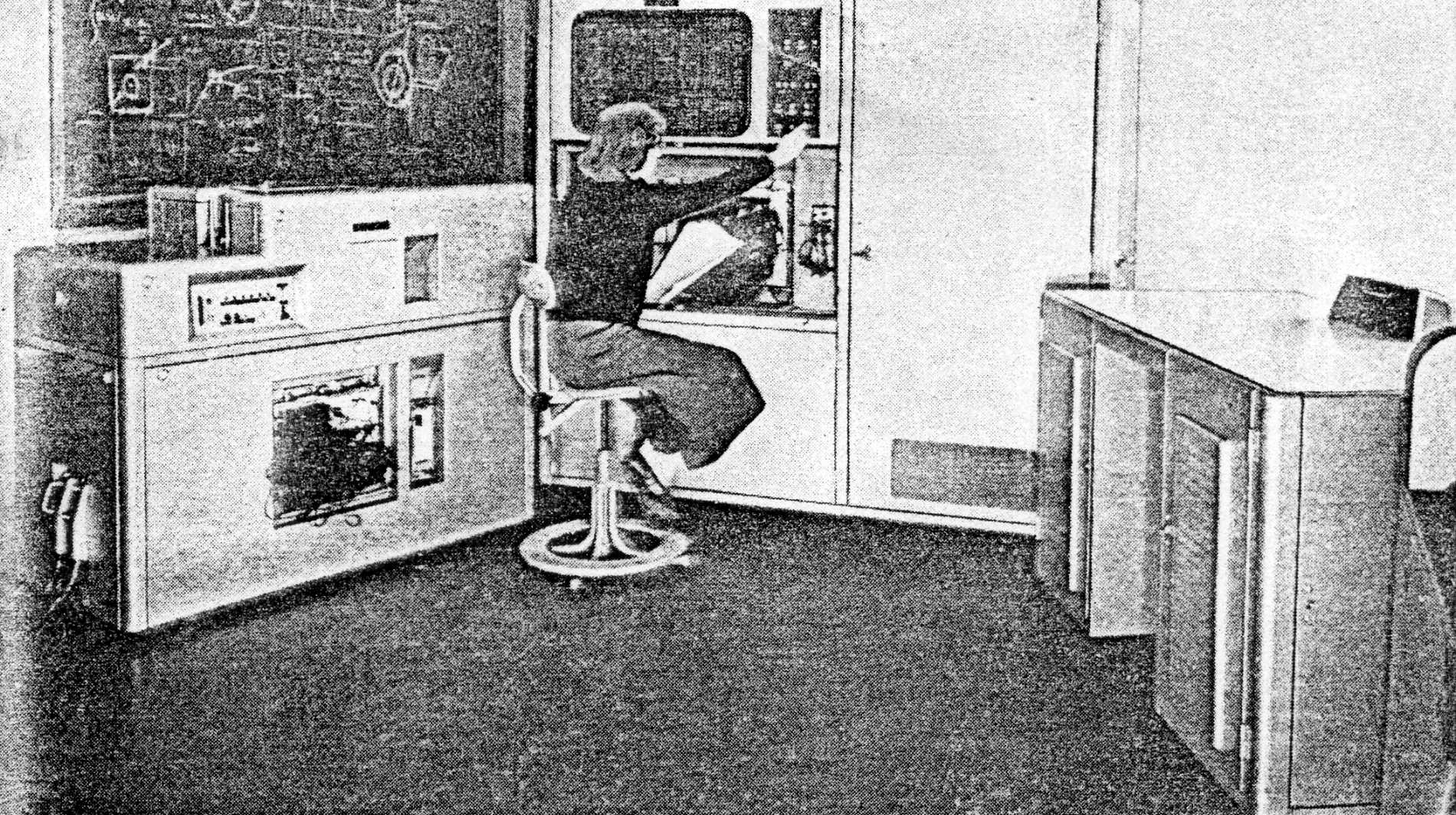
The Hollerith Type 555 Electronic Calculator is manufactured by The British Tabulating Machine Co. Ltd., and is a development of their Types 542 and 550 Electronic Calculators. The 555 was designed primarily for commercial and accounting work, but it has now proved to be also a machine which can be used usefully and efficiently in scientific computation.
The following account is intended to show, by means of some examples, the powers of the Type 555 Electronic Calculator in various types of scientific work. These examples have been chosen from problems dealt with by the Computer Group at A.E.R.E. Harwell, which has a Ferranti Mercury electronic digital computer and a Hollerith punched card machine installation including two Type 555 Electronic Calculators. The latter installation which is complementary to, and not in competition with, the Mercury computer is used in general for two types of work; Monte Carlo calculations in connection with reactor studies, and the processing of experimental data.
Although the Type 555 Electronic Calculator has been chosen primarily to carry out this work at Harwell, various other problems have been dealt with and this account includes a selection of such problems. It is intended to show what order of complexity and size of problem can be conveniently handled within the capacity of the machine, and to give information about the time required to program such problems.
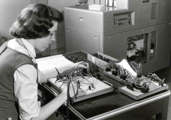
The Type 555 is an Electronic Calculator with card input and output, controlled by means of manually plugged control panels; the machine reads information from a punched card, performs a sequence of arithmetical or logical operations on this information (as defined by a program), and punches the results into the same or following cards. The program comprises a maximum of 150 steps but any group of these can be repeated, either a fixed number of times or until some desired result is achieved. The machine operates at a maximum speed of 6,000 card passages per hour. At this speed of input a fixed time of 600 milliseconds is allowed for reading in the numerical data and carrying out the calculation regardless of the complexity of the program. Should a calculation on a job call for more than this standard time allowance then card feeding will be held up until the calculation is completed.
Experience here ranges down to the feeding of one card every 50 minutes.
The machine uses decimal arithmetic with words or numbers of 10 digits; the internal representation is in binary coded decimal, each digit being represented by four binary digits which in all operations are dealt with in parallel. There is a magnetic drum store for 105 words of numerical data arranged in five channels each of 21 words. In a program step a number is withdrawn along either or both of two highways, put through functional units (e.g. adder, divider) according to the operation to be performed by that step, and the result returned to store. All operations take place in multiples of a word time or cycle (13/14ths milliseconds) during which, for example, the sum of two numbers can be formed and stored. Some operations, including multiplication, although constituting only one program step, occupy a varying number of word times depending on the size of the numbers involved.
Among features which make the Type 555 Electronic Calculator a powerful and efficient tool for scientific computation are:-
To summarise, the important features are:-
The general logical design of the machine is straightforward, and apart from a few special operations the instruction code is quickly acquired. The limit of 150 program steps and some slight restrictions on other facilities is countered by the fact that there is scope for considerable ingenuity in programming, especially when the program as first written exceeds capacity. This has frequently happened at Harwell, but it can be said that some means has always been found to overcome this apparent difficulty.
The actual plugging of a program by means of the control panel might seem at first sight to involve difficulties because of the closely packed plugs; plugging, however, can be reduced to an almost faultless operation if it is carefully planned at the outset. A simple code and routine is used, which enables even a stranger to a program to follow a calculation when checking through all its stages of plugging and operation; this greatly assists in fault-finding.
The design of the control panels is such that the number of times a particular function may be used is variable; there is an upper limit to the total number of functions of all kinds which may be called, but experience so far shows that this limit is unlikely to be reached and it is therefore not a factor which has to be taken into account by the programmer.
Examples of current problems have been chosen to show the use of the various features of the Type 555 Electronic Calculator: these have been presented to the Harwell Computing Group by scientists who have a practical need for large scale calculations. Some of these applications have become standard routines on which already hundreds of hours of machine time have been used.
It is almost always necessary in mathematical work to use one of the elementary functions, e.g. log, sin etc.; it is therefore important to have available routines which will evaluate these functions since the storage of tables is seldom desirable or even possible. Much work has been done in the last few years on finding approximations to the elementary functions using rational functions (i.e. ratios of polynomials which are sometimes obtained by means of continued fractions). There are a number of rational approximations which can be used.
Rational Approximations of Functions. B Carlson and M Goldstein, Report LA-193, Los Alamos.
When a specified accuracy is required it is imperative that an efficient routine is chosen for the Type 555 Calculator which uses only the minimum number of program steps consistent with the required accuracy. The fact that the division and square root routines are built in is, of course, instrumental in making the machine a powerful computing tool, for without these being available immediately and occupying only one program step much of the work which can be done would be impossible if sub-routines for these had to be programmed.
Experience with the Type 555 shows that between 20 and 30 steps are needed to evaluate such functions with maximum relative errors in the range 0.001 to 0.0001. For example, one such routine for evaluating abs(logex) takes 28 steps for a maximum relative error of 0.0004 over the range 0 to 1.
The rational function taken is:
x which may initially be 9 decimals, is scaled first by powers of 10 to obtain significant digits in the first five decimal places, and then by powers of 2 to bring it within the range 0.5 ≤ x ≤ l. This scaling and the subsequent correction by adding multiples of loge2 and loge 10 takes 18 of the 28 steps, the remaining 10 steps being used to evaluate y above.
Where two functions e.g. |loge x| and sin 2πx, are required in the same program it is possible to obtain rational functions which differ only in the numerical coefficients, thus allowing the same routine to be entered to evaluate both functions. (The |loge x| routine is given in Appendix A).
The active agents in a nuclear reactor are the neutrons, and the essential purpose of all reactor calculations is to find out something about the neutron population. This population is discrete, that is, it is made up of individual neutrons whose behaviour is governed by known physical laws which involve the nuclear properties of the materials of the reactor. The number of neutrons is so great (1010/c.c. is a low value for this) that no accuracy if the population is assumed to be continuous, and an analytical mathematical treatment of the problem developed as is done in hydrodynamics; a vast amount of reactor calculation has been, and will continue to be, done on this basis. However, problems have arisen in which the analytical treatment leads to mathematical difficulties insuperable even with the most powerful computing machinery, and in such cases, the only method of attack is one which takes into account the discrete nature of the neutron population. The laws describing this neutrons' behaviour are all expressions of probability: for example, the probability of travelling the distance x before making a collision with a nucleus is proportional to e-px where p depends on the medium. This collision can result in absorption or scattering of the neutron, or fission of the nucleus, with given relative probabilities. One can therefore study the behaviour of the system by computing theoretical life histories of sample batches of neutrons, using random numbers having suitable distributions to decide the course of each history; this is the mathematical equivalent of throwing dice or spinning a roulette wheel. Standard statistical theory can then be used to infer from the results of the sample calculation the properties of the population as a whole. This type of approach, called the Monte Carlo method, from an obvious analogy, has the great advantage of side-stepping all formal mathematical difficulties, but the disadvantage of giving a result subject to statistical error. This error can be estimated, and can be reduced by increasing the sample size (apart from using more refined techniques), but for high accuracy a very large sample may be needed. It is common practice to use samples of a few thousand neutrons from which one may usually expect to obtain final results correct to about 1%. This result is a generalisation, however, and is not necessarily reliable for particular applications. The basic operation in this process is the tracking of a neutron from one collision to the next; the 150 program steps of the Type 555 will often accommodate this even in systems which seem complicated, so that a collision is accounted for in a single card passage.
The following is a simple problem of reactor design, in which subject the application of Monte Carlo methods has received considerable impetus. A sample of neutrons is to be tracked through a system consisting of a series of plane parallel-sided cells. A specified number of these cells, which may be of different materials and widths, make up one block, and the system consists of an infinite series of such blocks. Each neutron having a given starting position, and a random direction, may travel a certain distance before collision with a nucleus. This distance depends upon the material through which the neutron passes and its magnitude is the result of sampling from a known probability distribution. A neutron having a collision will be absorbed or scattered with given probabilities, according to the material in which the collision occurs. The proportion of neutrons absorbed in each cell of a block is required, together with the neutron collision distribution for a block, each neutron being tracked until finally absorbed.
The program written for the Type 555 deals with a maximum of 10 cells per block, so that any system of 10 or less cells can be studied. for the purpose of calculation only the distribution and proportion of neutrons absorbed across anyone block is of interest. Therefore, neutrons having collisions outside block are considered as having their collisions in block 0.
The following information is given:
The card sequence:
Master Card A contains hi Pi, i=1 to 6
Master card B contains hi Pi, i=7 to 10
Master card C contains H, constants for generating random numbers and
                          constants for evaluating logex
Detail Card D contains Z=Z0, different for each of say 20,000 sample neutrons
Summary Card E1 contains the number of neutrons absorbed in each of the 10 cells
Summary Card E2 contains the distribution of collisions across the ith cell, i= 1 to 10
The Master Cards supply the constant information to be placed in the drum store, all calculation is performed on card D as below, and the Summary Cards cause the transfer of information from the working section to the output locations of the drum:
Since a sample neutron may have a random number of collisions before being absorbed, it is not possible to give an exact calculator speed, but, where the average number of collisions per neutron was ten, the rate was approximately 1,000 cards per hour.
It should be noted that apart from the initial preparation of the starting values, no card handling is necessary. The results are punched in eleven cards which have only to be listed to provide the record of the run. No exact figures are available for the time required to prepare this program, but it was certainly less then 10 days from its conception.
The program takes 130 steps and it is of interest to note how much the program depends upon the Repeat and Special Repeat functions. Clearly, in the sequence of calculations above there is a good deal of searching through the drum store, not only to locate values, but also to find the correct counter to store the number of collisions.
There is an increasing demand from physicists and chemists who require to summarise and transform results from large scale scientific experiments. The automatic output of data on to punched cards or tapes, which are then processed by a computer or calculator, saves great manual effort and also allows results to be inspected soon after an experiment has been completed. In many cases the calculation required is only of moderate size, but it may have to be repeated a great many times. It is therefore important to have a computer which can readily cater for a steady stream of such data.
In the design of nuclear reactors the nuclear properties of the materials to be used are of great importance; these properties are the fission, absorption and scattering cross sections of the fuel, the moderators and coolants, which in general vary also for the different energies of the free neutrons. These cross sections are simply the probability of anyone of the three events ocurring when a free neutron of a particular energy has a collision with a nucleus. There are several methods for determining these cross sections; the neutron velocity selector or chopper, the neutron crystal spectrometer, the Van de Graaff electrostatic generator, the linear accelerator, and the reactor itself. In almost all methods the behaviour over wide ranges of energy must be observed, so that for each material examined a large amount of data may be obtained, usually in the form of counts of neutrons as indirect functions of energy. The experimental physicist using these machines cannot make use of this information as it is obtained, because of its volume and because it is not in the form he requires, Le. cross sections as a function of energy.
The Type 555 is an efficient machine for this kind of work, and an illustration, dealing with cross section data from the linear accelerator, as carried out on the machine, is discussed. Although the calculation is small it will be seen that the amount of input and output data is considerable.
Information obtained from 1,000 sources, gives rise to 1,000 numbers ni. Several runs of the experiment are made giving input data of, say r sets, each of 1000 numbers jni, i=1 to 1000 and j=1 to r. It is required to calculate:
The calculation of 1/n |loge Ti| = σi makes use of the rational approximation discussed previously. In order to deal with a wide range of the numbers which can arise during the calculation, double length arithmetic has been used in steps 3, 5, 7 and 8.
The card sequence is as follows:
Master Card containg constants T C R K etc and constants for calculating loge Ti
Detail Card 1ni
Detail Card 2ni
...
Detail Card rni    for i=1,1000
Summary Card Source i - Output and Input of Ci, Si
The time taken to calculate 4 sets of 1,000 such numbers followed by 1,000 summary cards is 50 minutes; i.e. the calculator is running at full speed. The program, and the job itself, were dealt with entirely by junior staff.
There are other similar processes at Harwell and the demand for schemes such as that described above is increasing as the potentialities of automatic recording and processing are realised.
The following calculation is again one of nuclear physics and is unusual because very little arithmetic is required. For each stage of the problem numerous decisions must be taken, following a set of given rules, to determine which of a group of numbers on the drum store is to be operated upon. The Table Look Up feature, one of the facilities of the Type 555, is at the heart of the problem, and the following notes explain its essential points and the program instructions.
A table is in channels 1 and 2 having 42 entries assumed to be at equal intervals of the argument, e.g. F(E) for E ranging from 0.01 to 0.42 in intervals of 0.01.
As the result of a calculation of E we have, say E0 , and we wish to find F(E0). With the value E0 in the product register P, the following routine is entered.
(1)  Set TCOl> 0 by the transfer of a positive number and reset the channel selector.
     From the product register P on path A.
     Emit 21, on the path B (Complement if TCOl > 0).
     To the Product register.
     Set TCO1 and move channel selector.
     Repeat Program Step if TCOl > 0.
     Word time, instantaneous.
(2)  From P on path A.
     Emit 1 position 1 on path B. Complement
     To P.
     Set TCO1.
     Special Repeat step if TCO1 ≥ 0.
     Word time 19.
(3)  From Channel 1, path A. if Channel Selector = 2
                  2  path A, if Channel Selector = 3
     To Multiplicand register.
     Word time, instantaneous
N.B. There is an important difference between the repeat and special repeat functions. repeat will repeat a program step, under the control of a TCO, either consistently at a specified word time, or, instantaneously to progress through successive word time in sequence. Special repeat must have a specific starting word time and will then use, in sequence, subsequent word times. Both functions are controlled by numbers passing through the adder and when a control condition no longer exists, that is TCO1 ≤ 0, in (2), the repeat automatically causes one more operation before passing on to the next program step. Program step (2) illustrates this, 21 being subtracted until the result in the product is zero or negative; the complement function is then cut off and the further operation restores the fractional part of 21 to the product register. The channel selector can then indicate which channel holds the number, the fractional part selects the appropriate word time by means of program step (3). Program step (4) then performs the required operation on the selected number.
This routine can be used also for placing constants on the drum and also when convenient for selecting numbers for output.
Many of the problems of mathematical physics involve the solution of differential equations. Analytical difficulties are however often encountered, and it is frequently necessary to obtain numerical solutions for which various numerical methods have been devised. An approximate method is to replace the differential equation by a finite difference equation which for many cases leads to an adequate approximate solution. Such a situation arises in heat flow equations, and the following account is concerned with the solution of the finite difference equations which approximate to the differential equation.
In this type of problem, an initial state j is given for a series of positions i, i = 1, 2 ... n, and it is required to compute values for each position at state j + 1. where the relationship between the jth and (j + 1) th state is given by a finite difference equation.
A program has been written for the Type 555 which deals with n ≤ 10; 63 steps are required in the calculation of all 10 positions of the jth state. Because one card cannot contain all values for the jth state, a second card to be punched is inserted. The card sequence is simple, the constants and starting values are read in from two master cards and all subsequent values are punched on the blank cards. The speed is such that 1,000 values can be obtained in approximately 3 minutes, further illustrating the advantage of the Type 555 for the output of a large amount of data. The programming time required only a few hours, the possible value of n having been decided previously. In common with the Monte Carlo and Combinatorial problems, the ability to select numbers from the drum store according to given rules is vital; without it the solution of many problems would not be possible on the Type 555 and it is this ability which brings the machine into the border line class between electronic calculators and general purpose digital computers.
Since the Type 555 is restricted to 150 program steps, and a relatively small numerical store for this kind of work, matrix operations would not, at first sight, appear to be convenient, but it is of interest to consider what can be done in this field.
Another inherent difficulty when the equations are ill-conditioned, is that of scaling; the Type 555 is not easily programmed to deal with floating point arithmetic, because the shifting operations are not simple. However, this can be overcome to some extent by careful attention to the basic logic of the machine and by ingenuity in programming.
For operating on large size matrices a large fast general-purpose digital computer is essential, but, for matrices of a small order r say, in the range r=3 to r=12, the Type 555 can be used to solve a set of equations and evaluate the determinant; the inversion of a matrix and the evaluation of its latent roots seem to be unsuitable because of the difficulty of storing all the elements of the matrix, together with the subsidiary matrices which are needed. From the many methods for the solution of simultaneous linear equations, a choice has been made of the Choleski method where A=LL'. So far only symmetric matrices have been considered, and the following discussion is exclusively concerned with them. There are two reasons for considering this method to be suitable for the Type 555. First, it is not necessary to keep all elements of L' in the drum store, so that matrices of order less than 12 may be considered; second, the method of solution allows one element of L' to be computed for each input of an element of A, thus allowing the cards to be used as a temporary store of L'.
A program has bee n written for the Type 555 based on this, and experience will show how successful it is in dealing with ill-conditioned sets. The general scheme adopted is as follows:
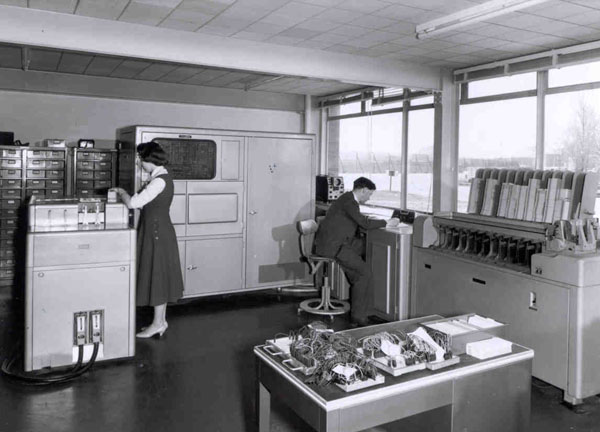
THE FIRST HOLLERITH 555 ELECTRONIC CALCULATOR is now in use by the Computing Group of the United Kingdom Atomic Energy Authority at Harwell. The machine will be employed almost exclusively for data processing and for computations involving use of the Monte Carlo technique. The first concerns the interpretation of measurements made with experimental facilities attached to the research reactors (BEPO, DIDO, etc.) and to the various high-energy particle accelerators.
Nuclear physicists at Harwell are undertaking very large programmes of measurements of fundamental properties of matter, essential to the proper development of reactor technology, as well as to the understanding of nuclear physics. In this, a great deal of calculation is needed to obtain from the data the information the experiment is designed to produce. The whole of the process is being mechanised by means of Hollerith Power Punches, directed and controlled by the apparatus concerned; by which readings are automatically recorded in punched cards. Calculations are made by the Electronic Calculator, at the rate of 6,000 card passages per hour, and their results are recorded in punched hole form. These can subsequently be printed out by Tabulator machine, or produced in graph form by a Dobbie-McInnes card-controlled plotter. It is estimated that the amount of calculating work required for even one major job at Harwell would need no fewer than thirty human computers; hence the decision to employ electronic machine aid.
The Monte Carlo mathematical-statistical method for studying physical phenomena, in which random processes occur, is being employed with the aid of the Electronic Calculator to trace the life history of neutrons, entirely by calculation. The first problem posed for Harwell's Hollerith Electronic Calculator concerned the leakage of neutrons down channels in a reactor, as, for example, those which carry cooling ducts. The method involves tracing the life histories of several thousands of neutrons - a sample survey - and using this information to predict the behaviour of the very much larger number of neutrons in the actual reactor. This type of problem, intractable by conventional mathematical methods, now becomes capable of solution with the assistance of high-speed electronic calculating machines.
THE HOLLERITH TYPE 555 ELECTRONIC CALCULATOR embodies features hitherto only available in electronic computers. These include magnetic drum storage; extended (pluggable) programming facilities, with limited conditional transfer; provision for the extraction of square roots and for carrying out iterative operations, and facilities for complete checking and marginal testing. The storage capacity is 1,050 digits (105 words).
