
The Image Processing Algorithms Library has been developed jointly by the Rutherford Appleton Laboratory and the Numerical Algorithms Group Ltd. (NAG Ltd.), Oxford with support from the Alvey programme.
Since even simple English words can hide a technical meaning it is worth explaining what is meant by an "image" in this context. An image is a picture which has been broken up into smaller pieces called pixels (picture elements). The intensity within each pixel is represented by one number. For this to give a good representation of the original picture the pixels must be small or, to put it another way, the picture must be broken into a lot of pixels. Typically these pixels are rectangular and in this demonstration most of the large images have 512 lines of pixels with 512 pixels in each line. The computer may be processing an image to make it easier for a person to understand or the processing may simply be the first stage before the computer goes on to try to extract information about what the image contains. The library deals with the first stages of image processing not the later reasoning to decide what is in a picture.
Work for the first release of the library has concentrated on images shown as shades of grey rather than colour. Alternative but complementary versions of the library have been developed in two computing languages; Fortran and C.
This demonstration uses code from both versions and illustrates some typical image processing functions, concentrating on four types of operation:
An original image as taken by a video camera and stored on a computer may be lacking in contrast and not ideally suited for viewing. In order to improve contrast for the human viewer an operation called "Histogram Equalization" is performed. This makes better use of the range of intensities allowed within the image so that the eye has an easier job to do. This is somewhat similar to adjusting the contrast control on a television set. The distribution of intensities before and after the operation is shown. This illustrates one important aspect of image processing, namely presenting the image in ways that make it easier for the person viewing it to extract information. A look at the new intensity distributions shows that the information between the peaks is now being squeezed into a smaller range. This illustrates that this operation is for the benefit of the observer rather than the computer which may have further processing to do and can make better use of the original information.
A common but far from trivial problem is to identify boundaries between different parts of a picture. (This is an example where the combination of the eye and the brain does a remarkably good job.) The first stage of one approach to this problem is shown using parts of the larger images.
First the size and direction of intensity changes near each pixel are calculated. The boundaries have relatively high values of intensity change. This operation is called a "Sobel" filter but we also show the results of two other ways of calculating the size of the intensity changes. One is a "Laplace" filter which shows up boundaries as a very sharp swing between bright and dark. Another uses a simple operation which replaces each pixel value with the difference between the brightest and dimmest pixel in a group which includes the pixel in question. The demonstrations continue with the results of the "Sobel" filter since it gives the direction in addition to the size of the change. The next step shows the result of selecting the brighter parts of the image. Instead of displaying the size of the intensity change (which we used to make the selection so we already know that it is a large number) we use colour to display the direction. We would therefore expect that along a boundary running in one direction the colour would stay the same.
This demonstrates how some simple operations can still lead to useful results. The brightness of each pixel is adjusted in different ways depending on its own brightness and that of other pixels which are nearby. First we show the effect of replacing each pixel by the dimmest pixel, then by the brightest and finally by the difference between these two. This last operation enhances boundaries. It is possible to adjust the number of neighbouring pixels used in these operations from just one to twenty. In the examples shown just the central pixel and its four nearest neighbour are used. The technical name for this type of operation is "grey-value morphology".
A major problem in storing and transmitting images is the large amount of data involved. There are techniques which can be used to reduce this amount and an example of one of these techniques is included in the demonstration.
The picture shown in this example originally contains 256x256 pixels or units of information. An operation called a "cosine transformation" is performed and the information is reduced to 64x64 units before the operation is reversed to recover the original picture. This is a very drastic reduction and this shows in some small spurious features which are introduced into the image. However the reduction in size of the image data by a factor of one sixteenth could be very useful if the image needs to be transmitted over a network.
In a short demonstration we can only show a few operations to try to give some feel for what is meant by image processing. It is worth pointing out that images contain a lot of data and as most of the main images displayed were 512x512 pixels, each of which is represented by 8 bits in a computer, the number of bits needed to record one image of this size is typically 512x512x8 or roughly two million. Our eyes and brain do a quite remarkable job in making some sense out of the real world!
The AMT DAP510 consists of 1024 processors arranged as an array of 32-by-32. This parallel computer was originally designed by ICL Ltd., but since 31 October 1986 it has been further developed and marketed by Active Memory Technology Ltd. of Reading. Its mode of operation is based on the principle of Single Instruction Multiple Datastream (SIMD), that is binary operations such as addition and multiplication can be performed on each of the 1024 processors simultaneously. Each processor can communicate with its 4 nearest neighbours (north, south, east and west) and data can be passed at high speed along row and column highways. This allows considerable flexibility for movement of data between processors. Opposite edges of the array can also be connected together to form cylindrical and toroidal arrangements of processors. While the DAP is running, its channels of communication are controlled by a host machine - in our case a SUN 3/160 workstation.
With all 1024 processors operating at the same time, the DAP has a peak performance of 10,000,000,000 operations per second!
The following demonstrations will be run in a continuous sequence on the DAP and all in one way or another make use of the capability of the DAP to carry out many operations at the same time. The pictures are displayed on a screen consisting of 1,048,576 picture elements which is driven directly from the DAP itself.
This demonstration illustrates the production of lifelike images by the method of ray tracing. The light intensity at each pixel (picture element) is computed by tracing light rays from the eye point through each pixel to object in the scene. This results in an image which features soft shadows, multiple lights, reflection and refraction.
Random displacements of an image are corrected in "real time" to freeze the image.
This is the problem of placing a number of queens on a chessboard such that no queen attacks any other; sizes of chessboard up to 32-by-32 are considered. The DAP solves the problem by generating boolean matrices to mark the lines of attack of the queens. The display shows the search for solutions in two phases;
This demonstration displays two members of a special class of fractals known as the Mandelbrot Set. Fractals form beautiful images of amazing complexity. Much computing power is expended in generating each of these l024-by-1024 pixel images.
An important feature of this demonstration is that "load balancing" is performed. That is, a processor can begin fresh work without having to wait for its neighbours to finish their work. This is illustrated by the "rippling" effect on the screen as the work progresses.
This example shows a relief map of the Isle of Wight and the shadow pattern cast by high ground as a radar scanner moves round the island. The scanning direction at any moment is indicated by an arrow.
This display shows the development in time of a disturbance starting from the centre of a square region. It is analogous to the effect of a pebble falling into a square pond.
A common task in image analysis is to label all the parts of an image which are connected. The DAP can solve this problem at very high speed because its processors are tightly connected and can communicate with each other at very high speed. As it recognises each component in an image it "labels" it by covering it with a checker pattern.
Yet more fractals - just enjoy the pictures!
Compared with a conventional workstation, the Stardent ST2000 has significantly greater computational and 3D graphics power. The demonstrations show these capabilities.
This demonstration shows a crankshaft and a piston as they move through their regular cycle. They can be viewed from any direction. Not only can the crankshaft and piston be shown in shades of grey, but lighting effects can be simulated. Lighting can help us perceive the gradients and shapes of a complex object.
Results of a pressure calculation can also be shown, by displaying the values encoded as colours on the head of the piston. The colours change as the pressure field changes as successive phases of the cycle are traversed.
To understand the structure of a molecule, it is useful to build a model, inside the computer. Some complex molecules can be modelled in this way. One of the molecules here is immunoglobulin which contains about 3500 atoms.
There is no single best way of visualising the molecule. Some ways focus on the atoms, others on the bonds between them. Several ways of visualising the molecule are possible with the program. One method displays the atoms as balls. Another displays the bonds as ribbons.
This demonstrations simulates the motion of up to 50 bouncing balls inside a box in 3D. Gravity is simulated and also the effects of elasticity when the balls collide - the effect can be bouncy or a dull thud.
Different starting patterns and different values of elasticity can be tried. The whole box can be turned over while all this is going on.
This shows the effect of harmonic oscillations on an elastic sphere. Just enjoy the distortions. Will it turn itself inside out?
Scientists and engineers know that one way to understand complex data is to use some graphical method of representing that data. Today's technology is opening up new ways of visualizing that data, using 3D methods. The AVS system is an example of a system that helps us do that. Data points inside a volume can be perceived using a number of techniques. If appropriate, data can be represented as a surface and the user can inspect the resulting surface.
This software shows the use of a new graphical input device, the spaceball. Where a mouse only works in 2D, the spaceball has other degrees of freedom. It responds to pressure from any direction and can also respond to an attempt to twist it. This can be particularly useful when trying to browse around and through a computer model of a 3D object.
Mathematica, described by its author, S. Wolfram, as "A System for Doing Mathematics by Computer", is essentially a computer algebra package with graphics capabilities
As well as performing numerical calculations, one of the most important features of Mathematica is that it can work with algebraic formulae as well as with numbers, including a large variety of mathematical functions.
On the Stardent ST2000, Mathematica can plot functions of one or two variables. One possible plot is to display a function, f(x,y), as a surface in 3D space, with the height of the surface representing the value of the function, and with the surface shaded or coloured according to height.
This program shows the vibrations of a disc being calculated and displayed by the ST2000. Each step takes a fraction of a second. (This program is not interactive)
Colour is determined by the spectral distribution intensity of visual radiation. The spatial distribution of the radiation sources may also be a factor. For example, "fake" colours are produced by patterns of moving black and white lines. Indeed, all the colours on a colour television are produced by only three monochromatic phosphors. Here, the phosphor dots arc so closely intermingled that the visual system is fooled into adding together the separate colours. It is fortunate that the mapping from spectral distribution to perceived colour is injective i.e. many physical colours will map to the same physiological colour. In this way, a television monitor can simulate a wide sub-range of colours without necessarily matching their spectral distribution.
What is clear, is that colour perception is a complex phenomenon and very much an artifact of high-level visual processing. Both physiological and psychological mechanisms are involved.
Colours may be represented by a number of models. Some of these models renect the method by which a particular technology reproduces colours (e.g. colour printing or VDU technology). Others correspond to the more intuitive artist's notions of colour, hue and shade. In fact, our own experience with red (a colour editor, see later) has shown that these anist's models are the easiest to interact with, and so tend to be the most useful.
A model which encompasses ALL light sensations we experience with our eyes is the Commission Internationale L'Eclairage (CIE) model. This forms an international standard that specifies all colours in terms of three distinct primaries. The whole range of colours covered by the CIE model, cannot be displayed by any current technology.
Any model used in computer graphics must ultimately be mapped to the representation that the output device employs, which in many instances is a description in terms of red, green and blue components. Therefore, there must be mathematical transformations to change between the numeric representations for the different colour models. Indeed, it is often such a transformation that defines a particular colour model in terms of another. All the models used by red are defined in terms of red, green and blue components.
Most colours models represent colours as a volume in "colour space". Any particular colour is represented as a point within this volume and is specified by three coordinates. A number of common colour models are described below. The names of these models are formed by concatenating the standard variable names used to represent the three coordinates.
Red is an interactive graphical colour editor. Frequently, to specify a colour for computer graphics you must supply the red, green and blue components (as three numbers from 0 to 255 inclusive). Choosing a colour is thus an iterative procedure involving first specifying the numbers, and then visually inspecting the results. A problem with this is that humans do not naturally think of colours in terms of numbers. It is not intuitively obvious how one should change the numbers of the currently visible colour to those of the desired colour.
Red attempts to circumvent these problems by presenting an easy to use what you see is what you get (WYSIWYG) interface, that allows colours to be chosen visually, without recourse to an intermediate numeric representation. Red supports all the colour models described above.
A typical display for a colour workstation will have the ability to display on screen 256 different colours simultaneously. However, each of these colours can be chosen from a much larger set of colours, usually 16,777,216 (i.e. 2124). A set of colours chosen for onscreen use is called a colour map.
To display a blue vase with as smooth shading as possible clearly requires a large proportion of the colour map to be devoted to shades of blue.
A colour map gives the advantage of being able to display any desired colour, despite the limitations on the total number of colours. Set against this, is the problem of resource contention which could arise if a smoothly shaded blue vase was to be displayed simultaneously with a smoothly shaded red vase.
A colour map can be regarded as a look-up table that determines the mapping between colour number (0 to 255) and visual appearance (red, green and blue components from 0 to 255). Skilful use of colour maps can provide many special effects such as transparency, animation and control over graphical object visibility.
Red allows colour maps to be manipulated as units. For example storing a colour map in a file, will allow another application to subsequently use this set of colours.
It will be possible to use red and gain experience of different colour models. There will also be an opportunity to match a given colour by adjusting the colour model components
The DataGlove is a light-weight glove-shaped input device. It senses relative hand movement, position and orientation, in real time. It converts this information into a computer-readable form. The glove monitors flexion and extension of the fingers and the position and orientation of the hand. The glove is made of lycra and is correspondingly light and elastic. The currently available version is called "The Data Glove Model 2".
The DataGlove is an example of a device that begins to create a virtual world for its operator. Physical reality is the thing we find on the other side of our sense organs: eyes, ears, and skin. Virtual Reality (VR) is perceived when computerised clothing is worn over these sense organs to give the impression the wearer is in a different or virtual world. These suits are sometimes called DataSuits. Examples of the Virtual Worlds that have been created include: -
The information on relative hand movement is obtained from fibre optics. Usually fibre optic cables transmit light. In the glove, the fibre optic cables at the joints are treated so that light escapes when the fingers bend. The greater the movement - the greater the loss of light. The remaining amount of light transmitted is measured. The glove includes a Polhemus device to give absolute position and orientation. It can also detect Yaw, Pitch and Roll. It is possible to buy extra sensors to detect abduction (the movement of the finger sideways) and for the minor joints. The Glove comes in both right and left handed versions.
The glove supports RS232 and RS422 communications and returns up to 60 records per second. The software supplied can detect a variety of gestures. A library of 25 commands is available to interface to the glove.
Only one glove is being used, but two handed input may be important for some applications. A dual system synchronization package is available to integrate two handed input.
Feedback is the information provided to the user about what they have done in the environment. Feedback would allow a user sense when they had 'touched' an object within the virtual reality. Currently the glove gives no feedback to the user but research is being actively pursued in this area. It could be possible to provided stimulation to the fingers to imitate tactile feedback, or sound could be used to indicate when an object has been touched. Some techniques for providing feedback are being considered :-
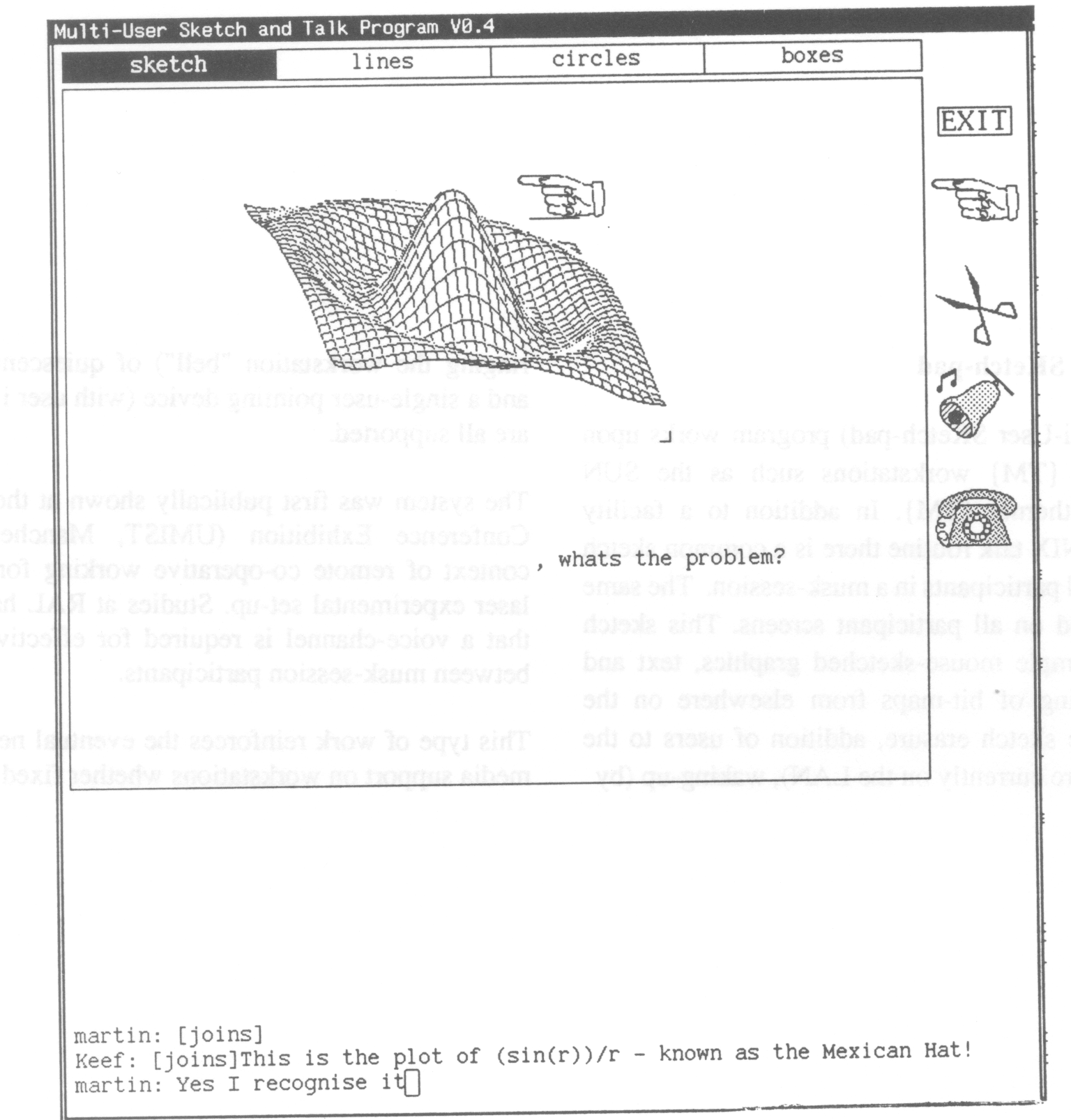
The Musk (Multi-User SKetch-pad) program works upon standard UNIX workstations such as the SUN connected by Ethernet. In addition to a facility similar to the UNIX talk routine there is a common sketch area shared by all participants in a musk-session. The same copy is displayed on all participant screens. This sketch area supports simple mouse-sketched graphics, text and "cut-and-paste"-ing of bit-maps from elsewhere on the screen. Selective sketch erasure, addition of users to the system (if they are currently on the LAN), waking-up (by ringing the workstation "bell") of quiescent participants and a single-user pointing device (with user i.d. displayed) are all supported.
The system was first publically shown at the 1987 Alvey Conference Exhibition (UMIST, Manchester) in the context of remote co-operative working for design of a laser experimental set-up. Studies at RAL have indicated that a voice-channel is required for effective interaction between musk-session participants.
This type of work reinforces the eventual need for multimedia support on workstations whether fixed or mobile.
Figure 1 (below): A Multi-User Sketch and Talk Program (musk) session. Each participant in a session gets the same presentation on their musk window. The major area of the musk window is taken up by a shared "sketch" area.
Crampton, C.M. (1987) MUSK - A Multi-User Sketch Program In Proceedings of the 1987 European Unix User Group Conference.
As part of the European Community's funded COMETT initiative the Zentrum fur Graphische Datenverabeitung (ZGDV) in Darmstadt, West Germany co-ordinated a project to provide an initial training and education programme in different application areas based upon computer graphics techniques. Partners in the collaboration came from West Germany, Portugal, Spain and the United Kingdom.
The major thrust of the project was directed at supporting both the tutor and the student(s) in a CAD training environment with appropriate hardware and software tools. Effort was expended upon courseware to give an introduction to human factors issues in the design of the user interface to computer systems. The emphasis of the course is upon design for the current high-power technical workSlltio!1s such as the SUN-3. It is expected that course participants (for the current version of the course) will have some familiarity with computers. Each person attending the course has access to a machine throughout the course. Emphasis is upon hands-on use of the machine and individual experimentation. This emphasis is supported by the newer instructional techniques being used in the course.
These newer techniques arc based upon the dedicated use of a high-power technical workstation for each course participant. These machines offer a highly interactive, multi-process, windowed working environment. Much of the interaction relics upon use of a pointing device (mouse) rather than keyboard. Although this style of working may be viewed as currently only applicable to a small range of users mainly working in engineering and science, this type of environment will increasingly be the norm for business and even home computing systems of the near future. Various firms connected with the City of London are currently making the transition from a standard PC to such an environment. The highly interactive, direct manipulation style of working with these powerful graphics workstations is not capitalized upon by a more static presentation style (that would be suitable for conventional "glass teletype" interface aspects of design). There are still some aspects of design that are common over a variety of systems (e.g. font-size and spacing for particular tasks) that can be shown in a static manner, but the ability to set-up comparisons interactively adds to the level of participation in the course and also reinforces specific points of design.
The course incorporates significant dynamic and novel "teachware" features in a context that permits the effectiveness and acceptability of these newer techniques to be evaluated. In line with this dynamic approach the following "teachware" techniques are being provided for the course:
Parts of the courseware on show today are the colour editor, red, and the Multi-User-Sketch-Pad, MUSK.
