Contact us Heritage collections Image license terms
HOME ACL Associates Technology Literature Applications Society Software revisited
Further reading □ PrefaceContentsMembers1 Welcome2 Introduction3 EDSAC4 EDSAC Demo5 Relay Computers6 Discussion7 CRT Storage8 Coding9 Library10 Sign Correction11 Nozzle Flow12 Magnitude13 France14 Checking15 Large Integers16 Discussion Storage17 Magnetic Storage18 Magnetic Recording19 Photographic Store20 EDSAC Auxillary Store21 Circuit Checking22 Circuit Checking23 Addition Circuit24 Trigger Circuits25 Checking26 Discussion27 USA28 Comment29 Holland30 Ficticious Traffic31 Sweden32 Manchester33 Discussion34 Bibliography
ACD C&A INF CCD CISD Archives Contact us Heritage archives Image license terms

Search

   
ACLLiteratureOther manualsCambridge Conference 1949 :: High Speed Automatic Calculating-Machines 22-25 June 1949
ACL ACD C&A INF CCD CISD Archives
Further reading

Preface
Contents
Members
1 Welcome
2 Introduction
3 EDSAC
4 EDSAC Demo
5 Relay Computers
6 Discussion
7 CRT Storage
8 Coding
9 Library
10 Sign Correction
11 Nozzle Flow
12 Magnitude
13 France
14 Checking
15 Large Integers
16 Discussion Storage
17 Magnetic Storage
18 Magnetic Recording
19 Photographic Store
20 EDSAC Auxillary Store
21 Circuit Checking
22 Circuit Checking
23 Addition Circuit
24 Trigger Circuits
25 Checking
26 Discussion
27 USA
28 Comment
29 Holland
30 Ficticious Traffic
31 Sweden
32 Manchester
33 Discussion
34 Bibliography

4 Demonstration of the EDSAC: W Renwick

Account prepared by Miss B.H. Worsley.

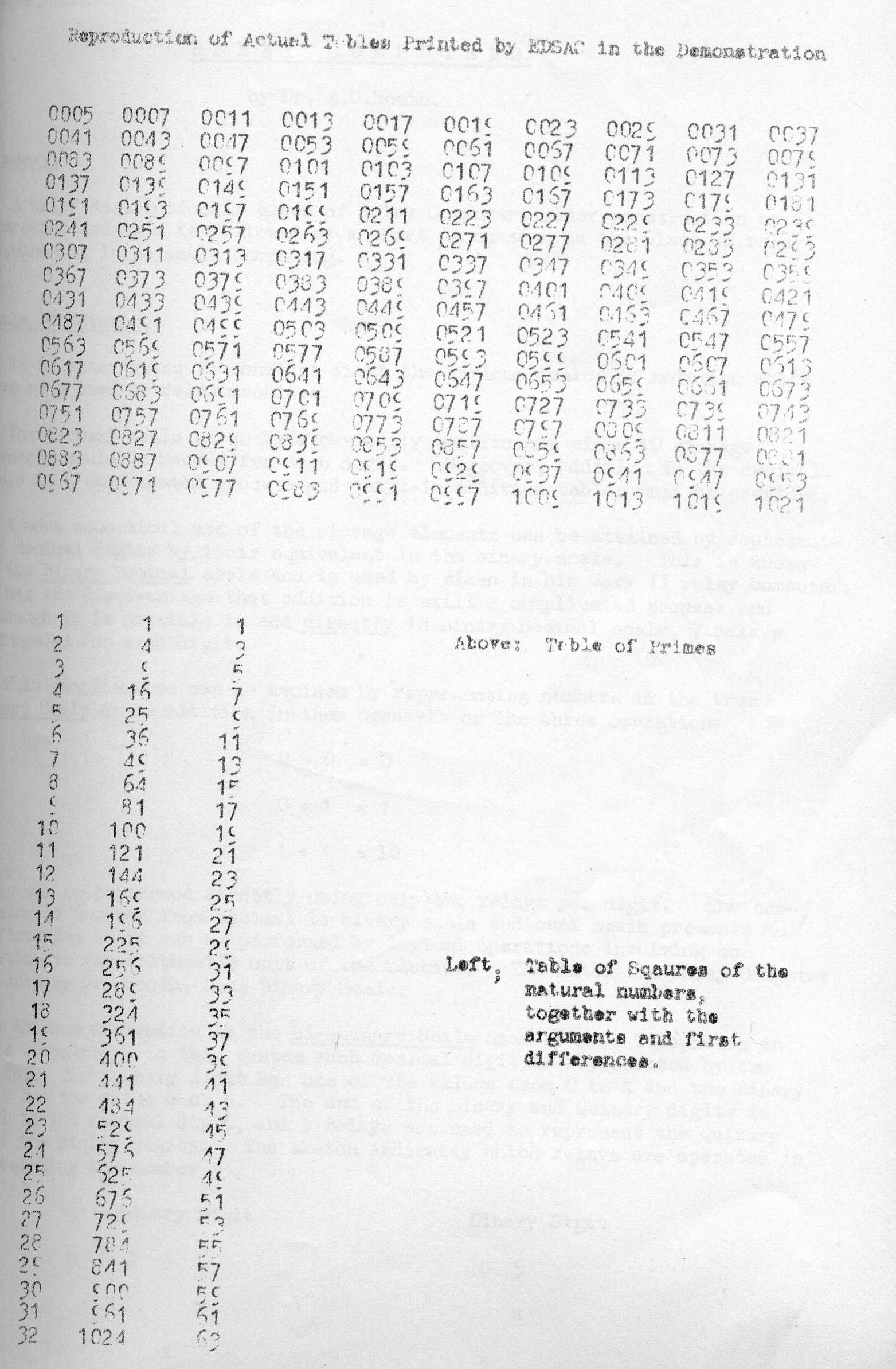
During the first day of the Conference, a demonstration was given of the new Cambridge Calculator, the E.D.S.A.C. In this demonstration, tables of both squares and primes were printed. These two problems have served as test routines for the machine, and are detailed here for the record rather than as examples of elegant programming. No attempt will be made to explain all the tricks and devices available to the programmer. However, it is hoped that the following notes, flow diagrams, and annotations will render the actual routines used in the demonstration intelligible.

Description of the Demonstration.

The following sequence of events was observed:-

  1. The teleprinter tape, punched with the orders (ii) or (iii) (see [below) was put in place on the tape reader, and the start button was pressed. The remainder of the operation then proceeded without further intervention on the part of the operator.
  2. The initial orders (i) (see below) were then input directly into the first 31 short store positions through the action of the uniselectors. These orders, used in every problem, are pre-wired in their binary coded form on the uniselectors, from which they are transferred automatically to their appropriate store locations. This operation took about 5 seconds, and was accompanied by a series of clicking sounds at the rate of about 6 a second.
  3. The tape-reader was next brought into action so that the orders (ii) or (iii) were synthesized to their binary-coded form, and placed in consecutive store positions starting from position 31. This action was under the control of the initial orders (i), thus utilising the machine itself to effect the necessary conversion. Input was at the rate of one symbol per 150 milli-seconds; or, on the average, 1½ orders per second, one click being heard for each symbol.
  4. Finally, the teleprinter was seen to begin operation, the computation and output then being under the control of the internally stored |orders (ii) or (iii). The time between the output of consecutive primes became appreciable as the numbers tested became larger. The printing of the squares was about as fast as the typing action, namely, one symbol per 150 milli-seconds.

Throughout the entire operation, the contents of the following tanks were displayed on Cathode Ray Tube screens in the binary form in which they are used in the machine:

1.   The 16 words (32,short numbers or orders) in any one of the long storage tanks desired.
2.   The Accumulator. 
3.   The counter tank.
4.   The multiplier.
5.   The multiplicand.
6.   The order sequence tank.

Notes on the Routines.

  1. The E.D.S.A.C. order code was given by Mr. M.V. Wilkes in his description of the machine, and need not be repeated here.
  2. The Initial Input orders have been designed to take in orders in the following standard form:-
    (Code letter, for the operation) (Address in decimal form) (Code letter for long or short number) 
    
    Note that this is not the only possibility, but has been adopted as being the most servicable one.
  3. The initial input is only able to synthesize symbols into the standard order form. However, since, inside the machine, orders are represented as numbers, it is possible to input certain numbers in the form of orders. These will be called pseudo-orders. Thus, for example, P5S represents the number 5×2-15 inside the machine, and so may be interpreted as the number 5 multiplied by the scale factor 2-15. In these test problems it happens that all the numbers required can be built up from simple integers in this way.
  4. The layout of the printing is also under the control of the programmer. Thus, for example, by using the order OnS, where store position n contains ΔS, he can effect a line-feed on the typewriter. Special attention has to be given to the suppression of non-significant zeros, if that is desirable.
  5. In the routines, the store position is listed for external reference. Only the orders are punched on the input tape. Standard five-hole teleprinter tape is used, with a slightly modified code.
  6. The arrow indicates an entry point from another position in the routine. Normally, orders are obeyed consecutively.
  7. Quantities in brackets are changed in the course of the execution of the orders.

Notation.

S(n)    denotes store position n. 
C(n)    denotes the contents of store position n. 
A       denotes the contents of the accumulator. 
R       denotes the contents of the multiplier register.
n   =   0. 1. 2 .... 1023, i.e. a short store position. 
a to b  means to replace b by a.

ROUTINES:

(i) Initial Input

Memory    Order.   
position      
0         T    0   S
1         H    2   S    Set multiplier

2         T    0   S    Transfer control to 6
3         E    6   S

4         P    1   S    Pseudo-orders
5         P    5   S

6         T    0   S    
7         I    0   S    Input function digits;
8         A    0   S    shift to correct position in 0
9         R   16   S    x1 = 0

10        T    0   L

11        I    2   S
12        A    2   S
13        S    5   S   Input next symbol. Test for
14        E   21   S   digit or discrimnant
15        T    3   S

16        V    1   S
17        L    8   S   10x1 + b to 1
18        A    2   S
19        T    1   S

20        E   11   S

21        R    4   S   Length discriminant digit to acc
22        A    1   S

23        L    0   L
24        A    0   S   Form order and transfer to n
25       (T   31)  S

26        A   25   S
27        A    4   S   n+1 to n
28        U   25   S

29        S   31   S   Test for start of programme
30        G    6   S

A fuller description was included in a poster at the time.

FlOW DIAGRAM (i) Initial Input 10/16 to r Clear input relays Input of function digits and shift to correct position Input of symbol = b - + b - 10 Add length discriminant digit to the Acc Form order Transfer to n n + 1 to n M - n - + Start programme

Note: The first order to be punched on the tape for any routine must be T n S, where the last order is to be input to position n-1. Control is then automatically transferred to the beginning of the routine after the last order has been input by the above initial input routine.

(ii) Print squares

31        T  123   S   As required by initial input
32        E   84   S   Jump to 84
33       (P        S)  Use to keep count count of subtractions
34       (P        S)  Power of 10 being subtracted
35        P 10000  S   For use in the  decimal binary conversion
36        P  1000  S
37        P   100  S
38        P    10  S
39        P     1  S
40        Q        S
41        π        S   Figures
42        A    40  S
43        Φ        S   Space
44        Δ        S   Line-feed
45        θ        S   Carriage  return
46        0    43  S
47        0    33  S
48       (P        S)  Becomes number to be printed
49        A    46  S
50        T    65  S   Put O 43 S in S(65)
51        T   129  S   Clear S(129)
52       (A    35  S)  
53        T    34  S   Put power of 10 in S(34)
54        E    61  S   Jump to 61
55        T    48  S   

56        A    47  S
57        T    65  S 
58        A    33  S   To control printing
59        A    40  S 
60        T    33  S 
61        A    48  S 
62        S    34  S
63        E    55  S 
64        A    34  S
65       (P        S)
66        T    48  S
67        T    33  S  Print contents of S(48)
68        A    52  S
69        A     4  S 
70        U    52  S 
71        S    42  S  
72        G    51  S 
73        A   117  S 
74        T    52  S
75       (P        S)  End print
76       (P        S)  Becomes x
77       (P        S)  Becomes x2
78       (P        S)  Previous x2
79       (P        S)  Becomes Δx2
80        E   110  S
81        E   118  S
82        P   100  S
83        E    95  S
84        O    41  S   Set on print figures
85        T   129  S   Clear 129
86        O    44  S
87        O    45  S
88        A    76  S
89        A     4  S   x+1 to S(76) and S(48)
90        U    76  S
91        T    48  S
92        A    83  S   Set switch z
93        T    75  S
94        E    49  S
95        O    43  S
96        O    43  S   Double space
97        H    76  S
98        V    76  S   x2.215 to S(77)
99        L    64  S
100       L    32  S
101       U    77  S
102       S    78  S
103       T    79  S   Δx2 to S(79)
104       A    77  S
105       U    78  S
106       T    48  S   x2 to S(49) and print
107       A    80  S
108       T    75  S
109       E    49  S
110       O    43  S   Double space
111       O    43  S
112       A    79  S
113       T    48  S
114       A    81  S   Δx2 to S(48) and print
115       T    75  S
116       E    49  S
117       A    35  S   Test for finish
118       A    76  S
119       S    82  S
120       G    85  S
121       O    41  S
122       Z        S

A fuller description was included in a poster at the time.

FlOW DIAGRAM (ii) Print squares Preparatory: set on "print figures" etc Line feed Carriage return x + 1 to x x to S(48) Set switch Z to 1 Print C(48) as decimal integer Z 1 Calculate x2 , Δx2 x to S(48) Set Z to 2 2 Δx2 to S(48) Set Z to 3 3 x - 100 Stop + -

(iii) Print Primes (from 5)

31        T  107   S   
32        O   92   S   Figures
33        O   93   S   Line Feed
34        O   94   S   Carriage return
35        S    5   S   Set p
36        T    6   S
37        O   95   S   Double space
38        O   95   S
39        T    7   S
40        A   96   S
41        R    4   S
42        S   97   S
43        E   42   S   Test whether m a factor of n
44        L    4   S
45        A   97   S
46        G   45   S
47        S   98   S
48        G  100   S
49        T    7   S
50        A   97   S
51        A    4   S   m+2 to m
52        T   97   S
53        H   97   S
54        N   97   S
55        L   64   S   if m > sqrt(n) stop testing
56        L   64   S
57        A   96   S
58        E   39   S
59        T    7   S
60        A   96   S
61        U    1   S
62        A    4   S
63        T   96   S
64        A   99   S   go to next factor
65        T   97   S
66        S   88   S
67        T    7   S
68        H   91   S
69        A    1   S
70        E   72   S
71        V   91   S  If n Prime transfer to S(0)
72        S   89   S
73        E   71   S
74        A   89   S
75        T        L
76        O        S
77        H   90   S
78        V    1   S
79        L    4   S   Print C(0)
80        T        L
81        A    7   S
82        A   98   S
83        G   67   S
84        A    6   S   Test -p
85        A   98   S
86        G   36   S   If the 5th no. printed, linefeed, carriage return
87        E   33   S
88        P    2   S   = 4
89        P  500   S
90        J        S   = 8/10
91        P   16   S
92        π        S   Pseudo orders
93        θ        S
94        Δ        S
95        Φ        S
96       (P    2   L)n
97       (P    1   L)m
98        P        L = 1
99        P    1   L = 3
100       T    7   S
101       A   99   S
102       T   97   S
103       A    4   S   if n not a prime
104       A   96   S
105       T   96   S
106       E   39   S
FlOW DIAGRAM (iii) Print Primes n = 5 m = 3 Set to "print figures" p = -5 Line feed carriage return Find remainder of n ÷ m r=0 n + 2 to n 3 to m r≠0 m + 2 to m n - m2 - + d = - 5 Print digit d + 1 to d d - + Double space p + 1 to p p + n + 2 to n 3 to m n = Number being tested for factors m = Number being tested as factor p = Position on line of printed page d = Digit counter

Note:

  1. The odd numbers, n, beginning from 5, are tested
  2. Testing is done, by effecting division by repeated subtraction.
  3. Factors tested are 3. 5, 7, ..... m, where m need not exceed sqrt(n).
  4. L or S digit is treated as the least significant digit.

Fig 1: Reproduction of Printed Output

Fig 1: Reproduction of Printed Output
Full image ⇗
© UKRI Science and Technology Facilities Council
⇑ Top of page
© Chilton Computing and UKRI Science and Technology Facilities Council webmaster@chilton-computing.org.uk
Our thanks to UKRI Science and Technology Facilities Council for hosting this site