1. In the Radar method of locating objects, reliable information is not obtained from a single echo pulse; generally from five to ten pulses are required to produce a reliable measure. In the transmission of signals in the Central Nervous System a sensation or command is represented by a continuous pulse train of varying frequency. In a digital electronic computer however it is hoped that each piece of information can be represented by at single pulse; there is no question of repeating this information; there must be no question of this information being misread. The situation raises the problem of reliability in an acute degree. A single problem may involve the transmission and correct reception of 1010 pulses, and the correct functioning of 103 valves and 104 other components. The signalling system at Waterloo station involves about 107 relay operations per week, there are generally about 10 failures per week.
It seems fairly certain therefore that for some time faults will occur during computation. Three principles may be stated.
Various methods have been considered for achieving some or all of these results.
Doing it twice. This procedure checks the existence of intermittent faults but not of an identical fault in each trial. The method is similar in principle to that of using 10 pulses in radar.
It is significant in this context that with the B.T.L. Relay Computer about two thirds of faults are cleared by mere repetition, in other words intermittent faults form a large fraction of all faults. However, in the B.T.L. machine faults are detected in quite a different way and these facts are not adduced in support of the method of merely repeating each sequence.
This method is of great power. The disadvantage is that a fault is located only approximately, i.e. within a certain sequence. The computation can be stopped and previous work saved, but there is no guide as to what action should be taken to clear the fault. One concludes that there is an onus on the machine designer to assist in the closer location of physical faults.
From the coefficients of a binary number
x = a020 + a12-1 + a22-2 + ...
one can form a new number
w = a0b0 + a1b1 + a2b2 + ...
which has been called the weighted count of x.
In the Raytheon Computer (1.2) which is a serial machine
a0 = a3 = a6 + ... = 1
a1 = a4 = a7 + ... = 2
a2 = a5 = a8 + ... = 4
w = 1 + Σa0b0 is formed modulo 16 and carried with x in the computer in all cases.
Although 0 is represented by the absence of a signal the following checks are possible.
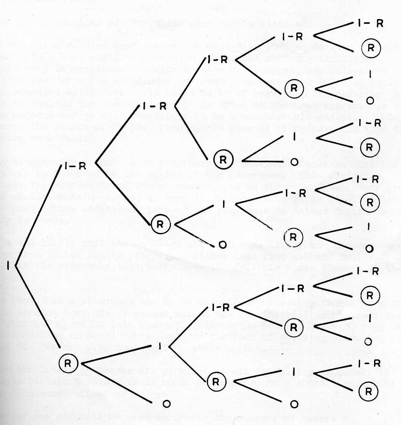
3.2 The fact that w is unchanged after a simple transfer, for example, does not completely check the transfer.
Suppose w max / x max = R
Then if wnew =w old and 1 error has occurred the probability that
xnew = xold is
If 2 errors have occurred the probability is 1-R
If n errors have occurred the probability is (1-R)n-1
In the Raytheon Computer R = 1/16, so that there is a probability that two errors will not change the weighted count.
It can be shown (Appendix I) that if between two checks there are a number of independent opportunities for error, and if λ is the product of the chance of one error and the number of opportunities then
(a) the chance of an error is ... 1 - e-λ
(b) the chance of an undiscovered error using a weighted count method is .. c-λR λ2/2l
so that:-
(c) the fraction discovered is approximately 2/Rλ
3.3 The properties of the method are:-
Gross checking at all key points.
Here for 100% increase in equipment, a fault can be located precisely in theory with one exception, namely the simultaneous occurrence of the same fault in the two computers. This effect is not quite zero. Imperfections of design will occur at the same points in both computers. Two human beings can both make the same mistake when performing the same task. The method is probably ruled out because of the 100% increase in equipment.
All the above methods have been devised to discover faults of which a very large fraction could be made self indicating.
The representation of 0 by the absence of a signal makes it difficult at the very start to distinguish 0 from a failure to transmit 1. This fact has been realised and avoided in the B.T.L. relay machine where two relays are used to represent a single digit, one is used for 1, and the other for 0. It is easy to check that one and only one relay has operated. It is believed that this idea is a fundamental step in the right direction, although for the relay machine the equipment is doubled.
The problem for the electronic computer is then to represent 1 and 0 actively in as economical method as possible.
5.1.1 On a single conductor positive and negative voltage levels lend themselves obviously to represent 1 and 0 respectively. Complements are obtained by simple reversal of polarity. A random series of 1's and O's will contain a d.c. component so that d.c. couplings are desirable.
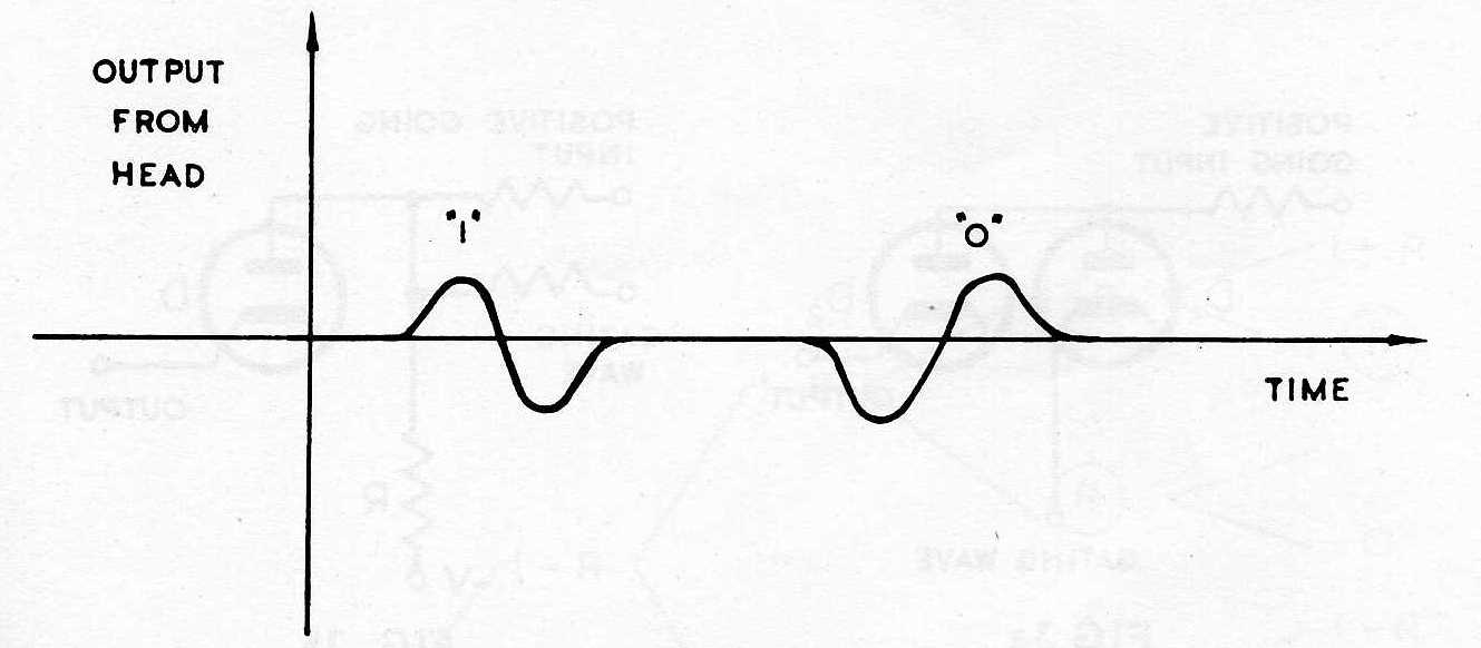
5.1.2 On a magnetic recording which is a kind of transformer balanced waveforms are desirable. Digits are represented by deltoid functions of flux, which are differentiated by the reading head as in Fig. 1.
5.1.3 As with relays two two-state methods, can be combined. The system can deal with all 1's, a corresponding system can deal with all 0's. This may lead to a doubling of equipment. The principle can be applied of storage systems, and conductors.
5.1.4 Special three-state trigger circuits have been evolved, in one example a pair of amplifiers in cascade are arranged normally to have overall negative feedback so that with no input both anodes rest at mid values. If however sufficient input current is supplied the anodes move so as to cause diodes to conduct. These diodes are in feedback paths which provide overriding positive feedback and cause a triggering action. These paths are called conditional feedback loops. The addition of four such loops to the basic two valve circuit results in three states of stable equilibrium. (Ref. 3)
Every subsequent introduction of four such conditional feedback loops results in two further states of stable equilibrium.
5.1.5 Special circuits for arithmetical and logical operations have been evolved which produce no active output if any input quantity fails to arrive. (Ref. 4)
By the above methods it is possible to check faults in transfer and arithmetic, and to locate them to within one or two values. See Fig. 2.
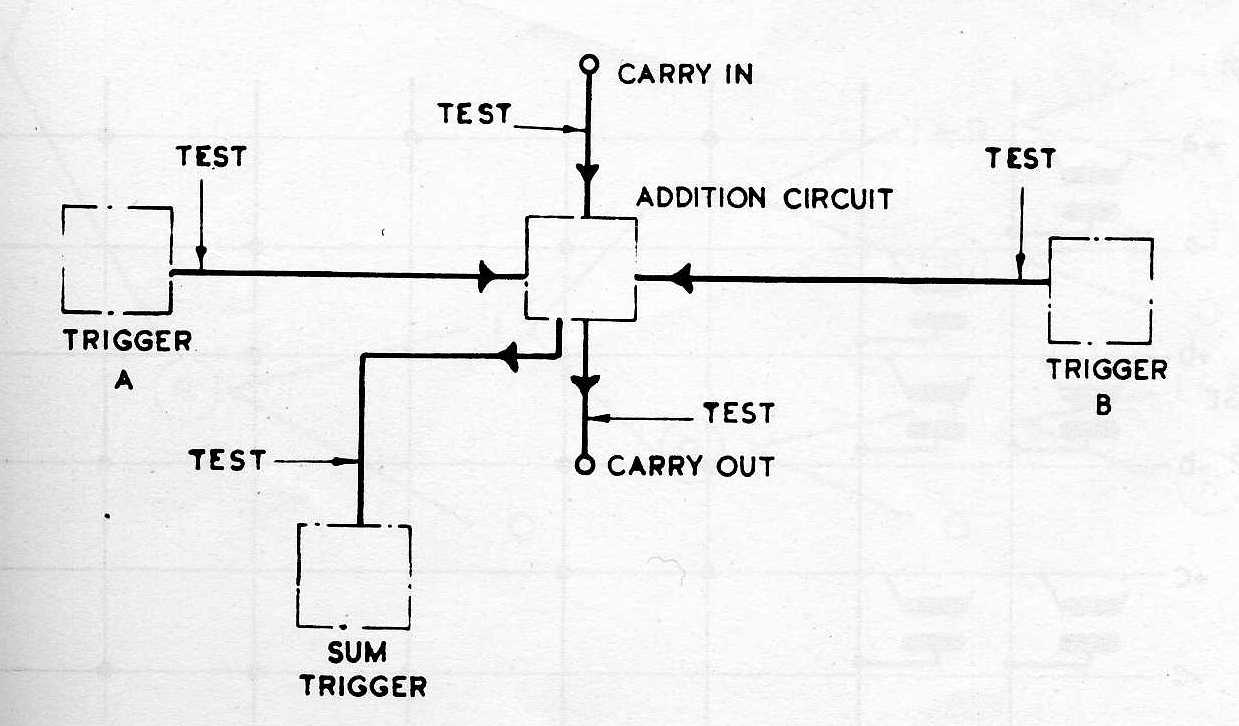
It is of course easy to stop the machine without losing past work.
In Railway Signal Engineering two causes of faults are distinguished; right side failures cause no incorrect information by merely halt or slow down traffic; wrong side failures result in incorrect information.
If a green light through some fault goes red, this is a right side failure. If a red light through some fault goes green this is a wrong side failure. If a red light goes out, this is a wrong side failure, and is analogous to the failure of a pulse to arrive in a two state computing system.
A century of progress in Signal Engineering has result in the almost complete elimination of wrong side failures.
Examples will be given of bad and good circuit design, from this point of view.
6.1.1 Diodes are frequently used to open gates according to one or more conditions. So that wrong side failures cannot occur diodes should be non-conducting in the inactive state; if then they fail to conduct the machine can be stopped with work unharmed. If diodes are cut off to open gates then diode failure will lead to permanently open gates. Examples of correct and incorrect diode gate circuits are given in Figs. 3a and 3b.
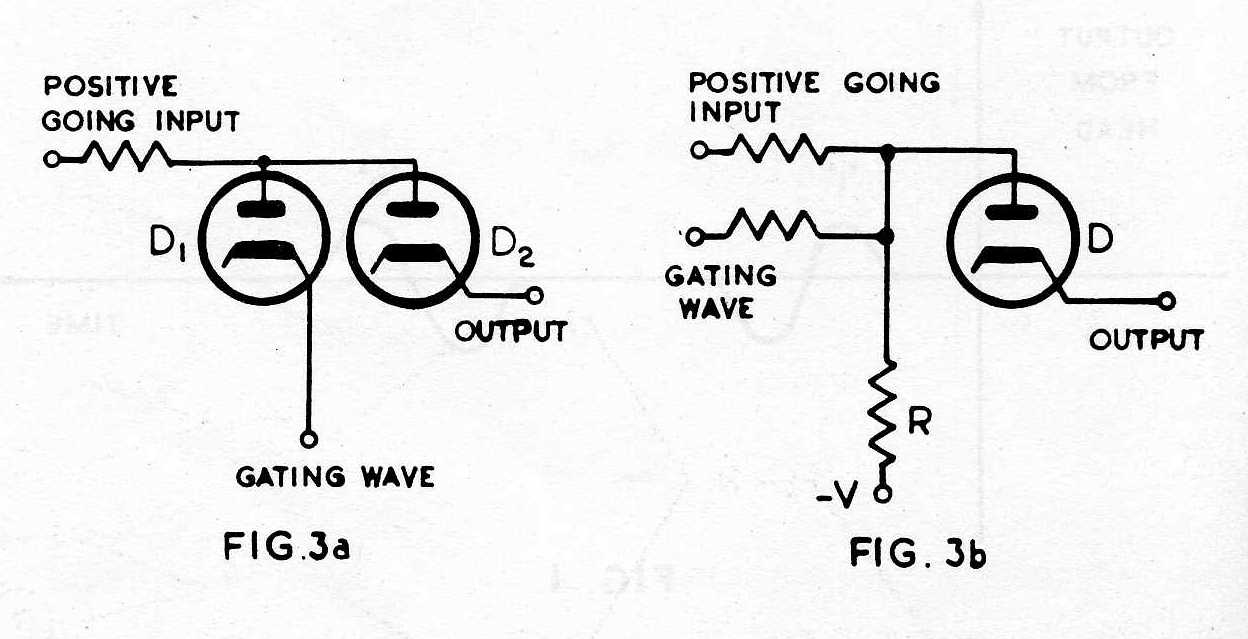
Assume that input, output, and gate points are normally at earth, and that it is required to gate through a positive pulse. In Fig. 3a if the gating point is held at earth potential the diode anodes cannot go positive for a positive input. Current is merely drawn through Dl; if Dl fails the gate opens.
In Fig. 3b the application of a positive input pulse causes, a certain current to flow in R, which will be insufficient to raise the diode anode above earth. The diode is non-conducting. If in addition the gating wave produces a current the diode anode will rise further and be caught at earth potential. No more current than V/R can now flow in R, the excess flows in the diode providing a current output. If D fails no signal can pass through the gate.
The added reliability is paid for by the introduction of two additional resistors.
A matrix frequently used is shown in Fig. 4.
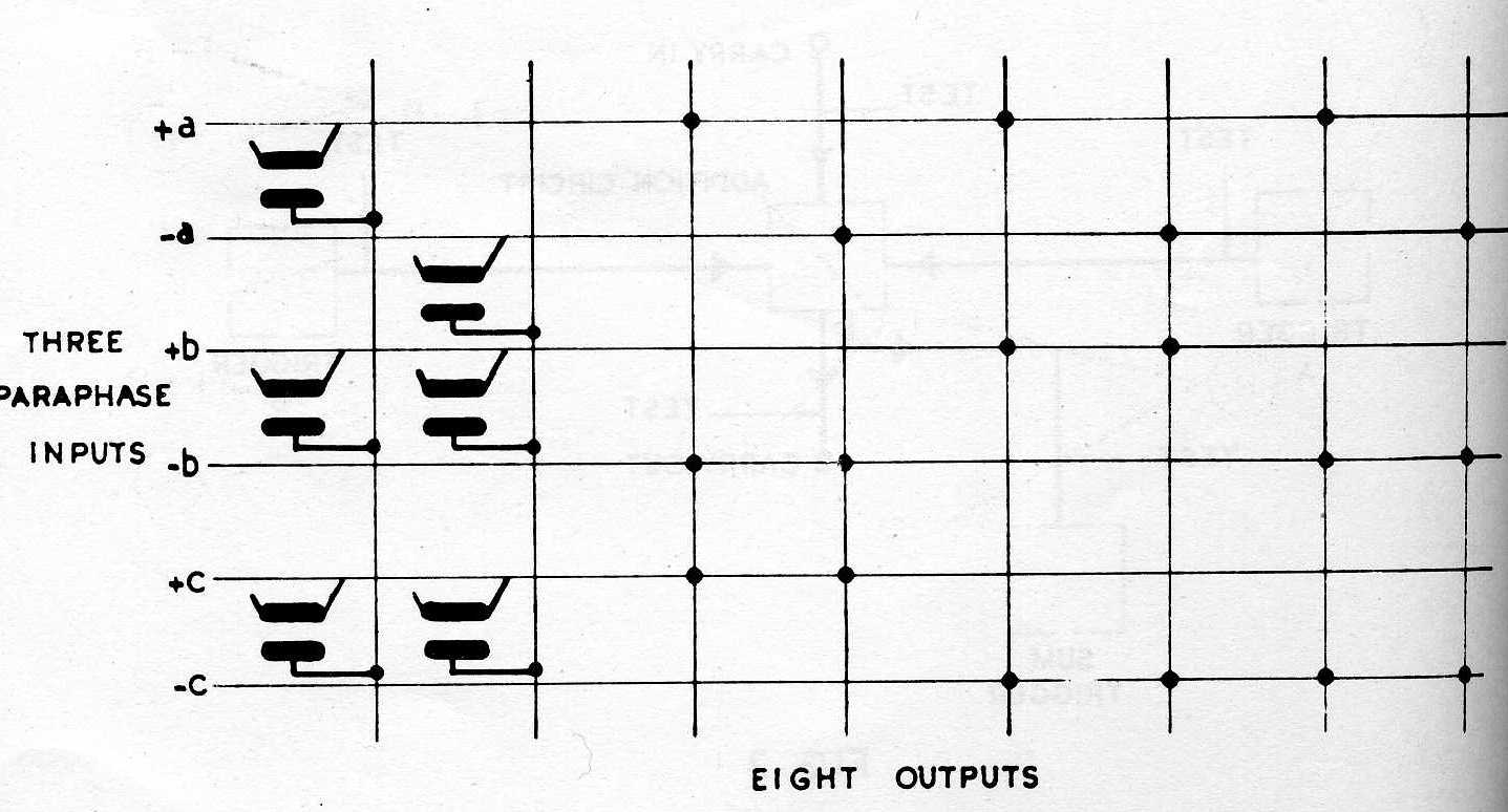
Output 1 can go positive only if three diodes are non-conducting. The whole circuit is full of wrong-side failures and can be redesigned on the lines of Fig. 3b.
6.1.2 Triodes A faster acting gate than 3b can be obtained by using a triode. The input is applied to the anode and a positive gating wave to the grid, current can flow only in the presence of both signals. This principle was used in Radar strobing circuits during the war. There are no wrong side failures. Accurate resistors are not used.
6.1.3 One concludes that thermionic elements must not be used in parallel as in Fig. 4. but serially. The grid and anode of a valve act serially on the electron stream. Extensions of the principle have been obtained by the use of pentodes, serial diodes and triodes with floating control of anode-cathode and grid-cathode voltage respectively; photo-multiplier tubes with many stages of secondary emission multiplication may prove a useful tool.
The failure of one valve in a trigger circuit will result in wrong information; it is a wrong side failure. If the principle of two active and one neutral state is used the trigger is cleared to the neutral state before information is gated to it. Two routine checks are carried out.
Ultimately, high speed electronic storage should have the three state property possessed for example by the magnetic storage method.
1. R. M. Bloch, R.V.D. Campbell, and M. Ellis. "Logical design of the Raytheon Computer". Mathematic Tables and Aids to Computation, National Research Council, Washington, D.C., Vol. 3 No. 24., October, 1948.
2. C. F. West and J. E. DeTurk. "A digital computer for Scientific Application". Proc. I.R.E. Vol. 36, No. 12, December, 1948.
3. S. W. Noble. "Electronic Trigger Circuits having several states of stable equilibrium". Conference Note.
4. R. H. A. Carter. "Checkable addition circuits". Conference Note.
Between any check and the next, there are many independent opportunities for error, each having a very small probability. The errors may be in different digits or the same digit of the number. If each independent chance of a single error is the same, then the probability of there being n errors altogether in this time is
λne-λ/n!
(Poisson, with mean equal to λ. λ is the product of the very small chance of a single error and the number of opportunities.)
If the independent chance were not equal, further information would be required.
The chance of the weighted count being altered by one error is certainty, but let the chance that an error will correct it be R.
Below the derivation is given of probabilities for an unaltered weighted count due to the combination of several errors. The ringed numbers apply to unaltered counts.
Chance of an unaltered count with
1 error   =  0
2 errors  =  R
3 errors  =  R(1-R) + R
4 errors  =  R(1-R)2 + R2
5 errors  =  R(1-R)3 + 2R2(1 - R)
6 errors  =  R(1-R)4 + 3R2(1 - R)2 + R3
etc.
Hence the total chance of undiscovered error
= e-λ [(λ2/2!)R + (λ3/3!)(2R-R2) + (λ4/4!)(R - R2 + R3) + ...]
Without weighted count it is 1 - e-λ
The efficiency of check measured by
Chance of undiscovered error or errors / Chance with weighted count ≈ (1-e-λ) / (e-λ R λ2/2!) ≈ 2λ/(Rλ2) = 2/Rλ
The 1/R is due to the inefficiency of the weighted count. The 1/λ is due to the fact that one error is ruled out. The factor 2 arises from Poisson distribution.