
Historically, the first step taken towards the construction of this machine was the development of the storage system [1], which uses charge distributions on the screen of a cathode ray tube as the storage mechanism. To nullify the inevitable loss of charge by leakage, this system necessitates sequential scanning and regeneration of the stored information during the so-called scan beats. In order to provide rapid access to any required stored data, these scan beats are interleaved with action beats, during which any desired address, of the main storage is scanned, as a result of a coded instruction. Decoding of instructions is arranged to occur during scan beats.
In the present machine, which is of the binary series type, the instructions have the simple basic form (s,f) where s is the line of the main storage to be selected, and f is the function to be performed on the content of that line.
The underlying principles of the present machine may, perhaps, be best understood by considering the schematic diagram of a miniature machine which was made, and operated, in June 1948. This diagram is shown in Figure 1.
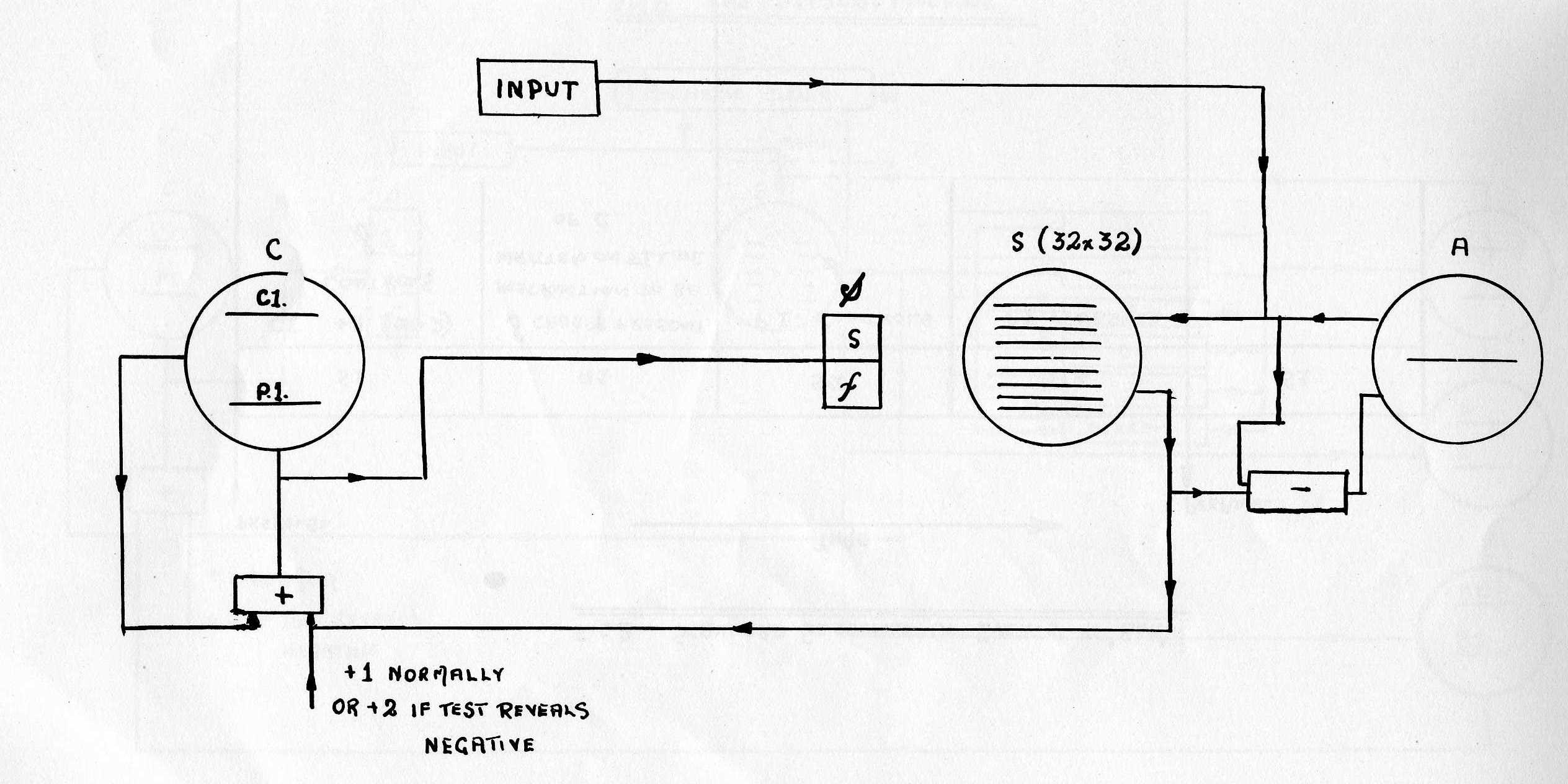
On the left of the figure is Control, C, a storage tube holding two lines and having an adding circuit in its regeneration loop. When a new instruction is required from the table of instructions stored in the main storage tube, S, a prepulse initiates the standard sequence of events summarised in Figure 2.
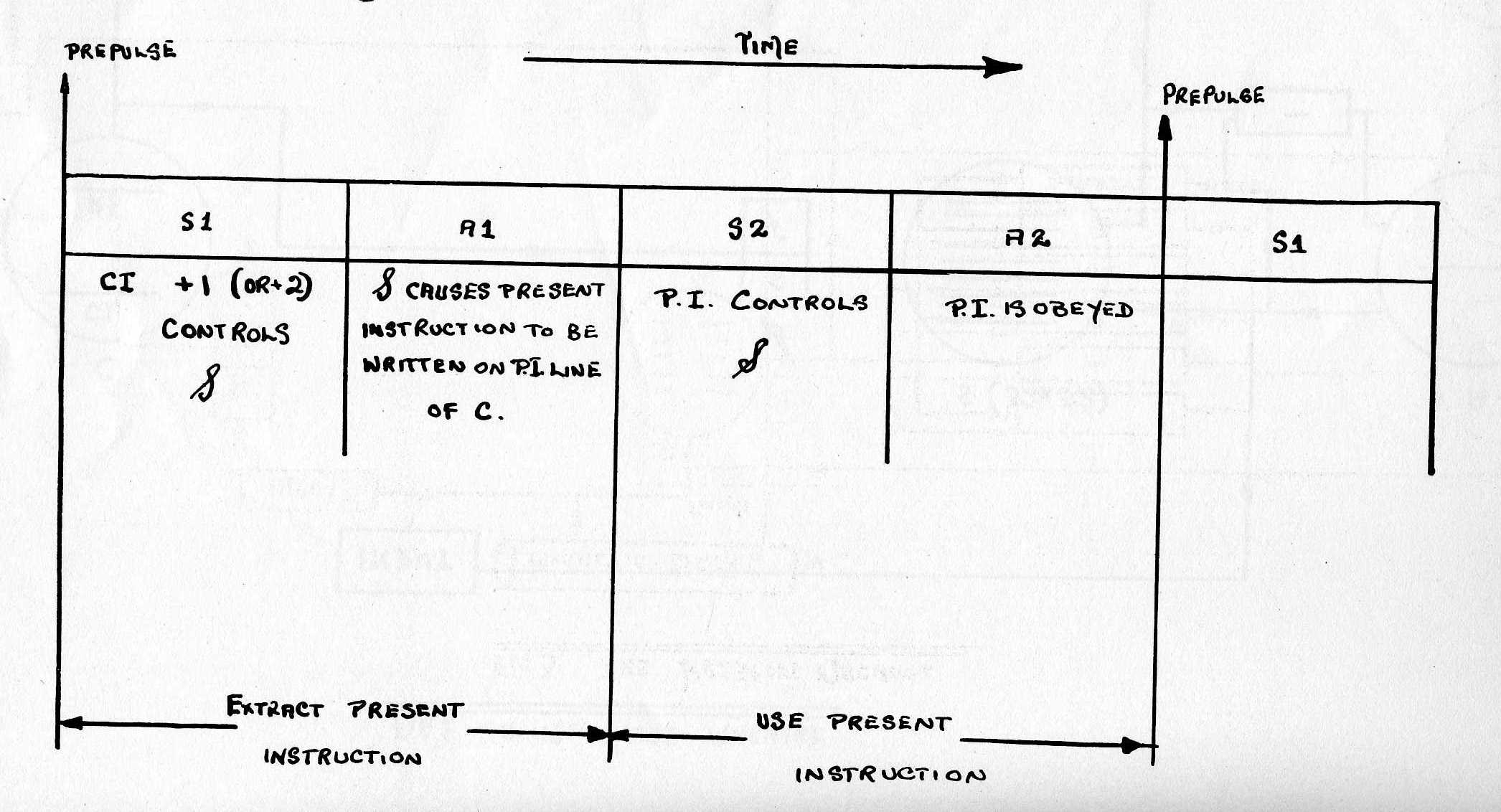
The beat following a prepulse is always a scan beat, S1, and during this beat unity is, in general, added to the C.I., or control instruction line of C, and the new content of C.I. controls the staticisor, S. During the following action beat, A1, the new or present instruction is selected from S and written on the P.I, line of C, as a result of the condition of S. During these two beats the content of C.I. has operated as an instruction to extract the next present instruction from S. These two beats are followed by two similar beats, S2, and A2, during which P.I., not C.I., is controlling S. Thus, in general, P.I. selects a line of S and causes some function to be performed on the contents of that line. At the end of the A2 beat the present instruction has been obeyed and a further prepulse is given. The time elapsing between adjacent prepulses is called a bar, and in this machine one bar contains four beats.
The function number, f, of an instruction may, during A2, cause a word (in general a number) to be (1) read from S and written, or added into, C, on the C.I. line; (2) written into the accumulator A, which is a single line storage tube, via the subtracting circuit; (3) subtracted from the content of A; or (4) the content of A may be written into a selected line of S. Two further functions are (1) to test the content of A to determine whether this is negative or not negative; and (2) to stop the machine when desired.
The facility of being able to add any stored number into the C.I. line, enables the position in the table of instructions to be changed in a relative manner and will be of assistance in connection with sub-routines. The decision to change the position in the table of instructions will be either unconditional or conditional. In the latter case, the sign of the content of A as determined by the test instruction is the criterion. If the content of the accumulator is negative, 2 is added to C.I. after the next prepulse, and one instruction in the table is omitted. This instruction, which may or may not be omitted, is one of the two by which the number on C.I. can be modified by transfer of a number from S. This method of obtaining a conditional change of the position in the table of instructions fits conveniently into the structure of the machine and the division of its operation into standard bar time units. Multiple branching at any point of the instruction table is arranged by modifying the number in S during the solution of a problem before transferring it to C.I. The remaining instructions mentioned in the preceding paragraph are self-explanatory.
The input mechanism of this machine consisted of a series of press buttons and switches by means of which the state of any stored digit in S could be reversed. Output was by visual inspection of a monitor CRT wired in parallel with S.
In this miniature machine the storage capacity of S was 32 lines, one line holding either one instruction, or one number. Each line held 32 digits. The bar period was 1.2 milliseconds.
The machine existing at present at Manchester University is shown schematically in Figure 3, and, as comparison with Figure 1 indicates, is a logical extension of the miniature machine just described.
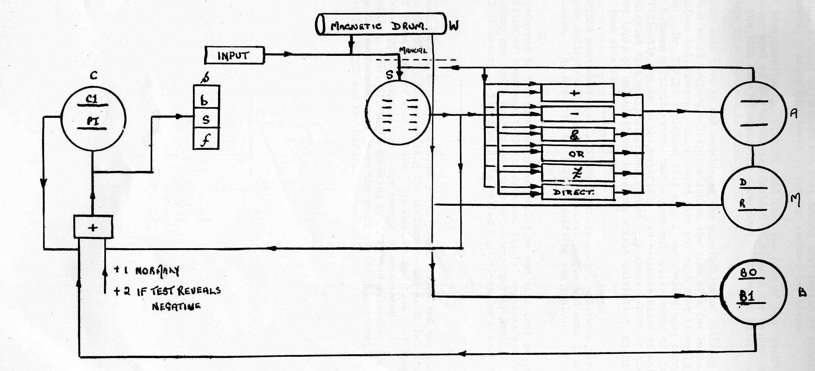
Detailed points of difference are the extension of the length of a line to 40 digits; the facility for putting two 20 digit instructions or one 40 digit number on a line; and the increase in the bar period to 1.8 milliseconds due to the increase in digits per line and the extension, for convenience, of the digit period to 10 microseconds (previously 3.5 microseconds). Important points of difference are:-
These -points are now discussed.
Associated with A are various computing circuits which deal with the numbers (words) received from S arithmetically or, in a logical manner, digit by digit. The adding and subtracting circuits are of the former type, whilst the and, or and not equivalent to circuits are of the latter type. Any of these circuits can be switched into the regenerative loop of A, as a result of particular instructions (see Appendix), but in the passive state regeneration of the contents of A is maintained via the so-called direct channel. In the active state any of the five computations above stated may be carried out between a number (word) from S and the content of A. When multiplying two numbers, the multiplicand is initially written from S into the multiplicand, of D, line of the multiplying storage tube, M. Then the multiplier is written into the multiplier, or R, line of M and multiplication occurs. The product, which, of course, contains 80 digits, is added into the accumulator A, and is stated on the two 40 digit lines of A. If all the 80 digits are required later in the computation, they may be written into two selected (40 digit) lines of S in two operations. Shift of a number, in either direction, may be achieved by multiplying by the appropriate power of 2, and writing the appropriate line of A into S. The time for multiplication is ½xT, where x is the number of 1s in the multiplier, and T is the standard bar period. Further prepulses are inhibited until the multiplication is complete. Instructions involving multiplying are relatively rare and thus the overall speed of computation is not appreciable retarded by multiplication.
The 40 digit numbers read from S are normally extended to 80 digit numbers when sent to A, by repeating the most significant digit (1 or 0) 40 times. This ensures the correct mathematical operation of A in terms of 80 digit numbers. In some cases, however, this repetition of the most significant digit is not done. For example, if it is desired to add two numbers of the order of 2400, each number will occupy 10 lines of S. Such numbers are always positive or are made positive by programming. Each of the 10 parts of one number is added to its corresponding part of the other number, commencing with the least significant part, the carried digit of each section being stated on the most significant line of A. The contents of the least significant line of A are then sent to a selected line of S, the least significant line of A is cleared, and the order of scanning the two lines of A is reversed. These processes are achieved in one operation. The carried digit is then in the least, significant position of A, and the remainder of A is cleared. This is the correct condition for proceeding to the next stage of the addition, and the answer finally appears on selected lines of S. It will be seen that this method allows as many as 40 carried digits to be recorded in A. Multiplication of numbers of greater length than 40 digits is achieved by a similar sectionalised process. In this connection, the treatment of the sign of a product may be discussed. When multiplying two forty digit numbers, with regard for the sign of the product, each is tested for sign and, if negative, re-written on the D or R line of M in its positive form. The numbers are then multiplied, and fed to A, via the adding or subtracting circuits associated with A, depending on the product of the signs, which is remembered in a suitable circuit. The net result is to add the product to the contents of the accumulator, as stated above. However, in multiplying long numbers, when the 40th digit of a line has no connection with the sign, the product of the 40 digit sections received from S are multiplied in their unmodified form, and always fed to A via the adder.
Storage tube B is a valuable auxiliary to the machine and is used for modifying instructions. Instructions can, of course, be modified by the normal processes (A and M, etc.) in the same way as numbers, but this is often inconvenient and wasteful of time and storage space. Therefore each instruction (S,f) is preceded by a single digit called the b digit. If b = 0 the content of line BO of B (normally zero) is added into the present instruction as this instruction is written into the P.I. line of C, i.e. before this instruction is used. If b = 1 the content of line B1 of B is used in the same manner. Numbers are written into B from S exactly as they are written into M, say.
The storage of a single 6" cathode ray tube has been increased to 2,560 digits, primarily by improvement in focussing. These digits are arranged in two rasters of 32 lines, side by side on the screen of the tube. Two such tubes form the main electronic storage S. This storage capacity is supplemented by magnetic storage [2] (see Figure 3) of 20,480 digits. Loading between W and S, and vice versa, is at present achieved manually.
Immediate future development of the machine will include the provision of more lines on the B tube; further extension of the capacity of S and W, as required; improved input and output facilities; and automatic interchange of information between S and W.
It is possible to arrange the rhythm of the machine so that each bar contains two beats, and thus increase the operating speed by a factor of 2. Briefly this is achieved by extracting the next instruction, whilst the present instruction is being used. This line of development may be pursued in the more distant future.
1.   s,C              - Transfer content of line s to C.I. line of C
2.   c + s,C          - Add content of line s to C.I. line of C
3.   s,B0             - Transfer content of line s to B0 line of B
4.   s,B1             - Transfer content of line s to B1 line of B
5.   s',D             - Transfer content of line s to D line of M and take note of sign
6.   s',R             - Transfer content of line s to R line of M and take note of sign
7.   s,D              - Transfer content of line s to D line of M
8.   s,R              - Transfer content of line s to R line of M
9.   a1,S             - Transfer content of least significant line of A to line s
10.  am,S             - Transfer content of  most significant line of A to line s
11.  a or s',A    )   Perform logical operations or, and, not equivalent to    |   In these
12.  a &  s',A    )   with  content of A and content of line s, and write      |   instructions
13.       s',A    )   result over the content of A                             |   the content of
                                                                               |   line s is
14.       s',A    )   Write the content of line s, via the adding or           |   extended by
15.      -s',A    )   subtracting circuits, over the contents of A             |   40 copies
                                                                               |   of its most
16.   a + s',A    )   Add to or subtract from the content of A, the content    |   significant
17.   a - s',A    )   of line s, and write the result over the content of A    |   digit
                                                                               |
18.       2s',A       Write double the content of line s over the content of A |

19.   a + s,A     )   Add the content of s (unextended) to the content of
20.   am +s,A     )   A, or to the most significant line of A

21.     0   ,A         Clear A
22.      Rev A         Reverse the significance of the two lines of A
23.  a1,S:0,A1:rev A.  Write a1 to S, clear a1, and reverse the significance
                       of the two lines of A
24.  am,S:0,am         Write am to S and clear am
25.       Test         Test the content of A for sign, as indicated by the
                       most significant digit in A
26.      Stop
[1] "A storage system for use with binary digital computing machines". IEE Journal, vol 96, Part III, No 40, March 1949; and Professor Williams lecture.
[2]G.E. Thomas' paper on "Magnetic Storage".
Prof, WILLIAMS said that the machine had run on one occasion from 9 p.m. to 6 a.m. without adjustment and that during that period it produced answers. After adjustment it ran for another two hours.
In reply to a question Dr. KILBURN said that the form of the "test" or conditional order used at Manchester was decided on because the technique they were using at the time made it specially convenient. It would be specially suitable for use in a two-beat machine.
Dr. KILBURN said that he had considered the possibility of building a multiplier which would perform multiplication in the time of a few beats. The mathematicians had, however, discouraged this and said that it would not be worth while. Dr. TURING explained that with a one address code there is so much to do between multiplications that a fast multiplier would not increase the speed sufficiently for it to be Justified. An estimate based on actual programmes indicated that multiplications formed only about 1/20th of the whole work. In some types of calculations, however, a fast multiplier, might be of greater value than this figure would suggest.
Prof. HARTREE mentioned Prof. AIKEN's estimate that 4 additions were required to each multiplication and said that other people had come to a similar conclusion. He did not know whether shifting was included in this estimate.
Mr. REY referred to the question of nomenclature and said that he thought the usual division of computers into analogue and digital machines was not satisfactory since one could imagine machines which were partly analogue and partly digital in nature. These might be called digital-analogue machines.
At the last session of the conference Prof. NEWMAN expressed the thanks of everyone to Mr. WILKES for organising the conference and said that the alternation of formal papers with informal discussions had been most successful. He also expressed appreciation of the large amount of work which such a conference entailed. Mr. WILKES in thanking Prof. NEWMAN said that the credit for organising the conference must go to the staff of the Laboratory, particularly to Mr. MUTCH and Mr. FARMER.
