
1.1. The machine is to be parallel operated using C.R.T. storage. The accuracy will be to 20 binary places or about 6 decimal places.
The digits 0 and 1 will be represented as far as possible in equally active manners, so that the failure of a 1 to arrive will be distinguishable from a 0; this will make possible simple checking circuits to detect electronic failures; this will be additional to mathematical checking procedure.
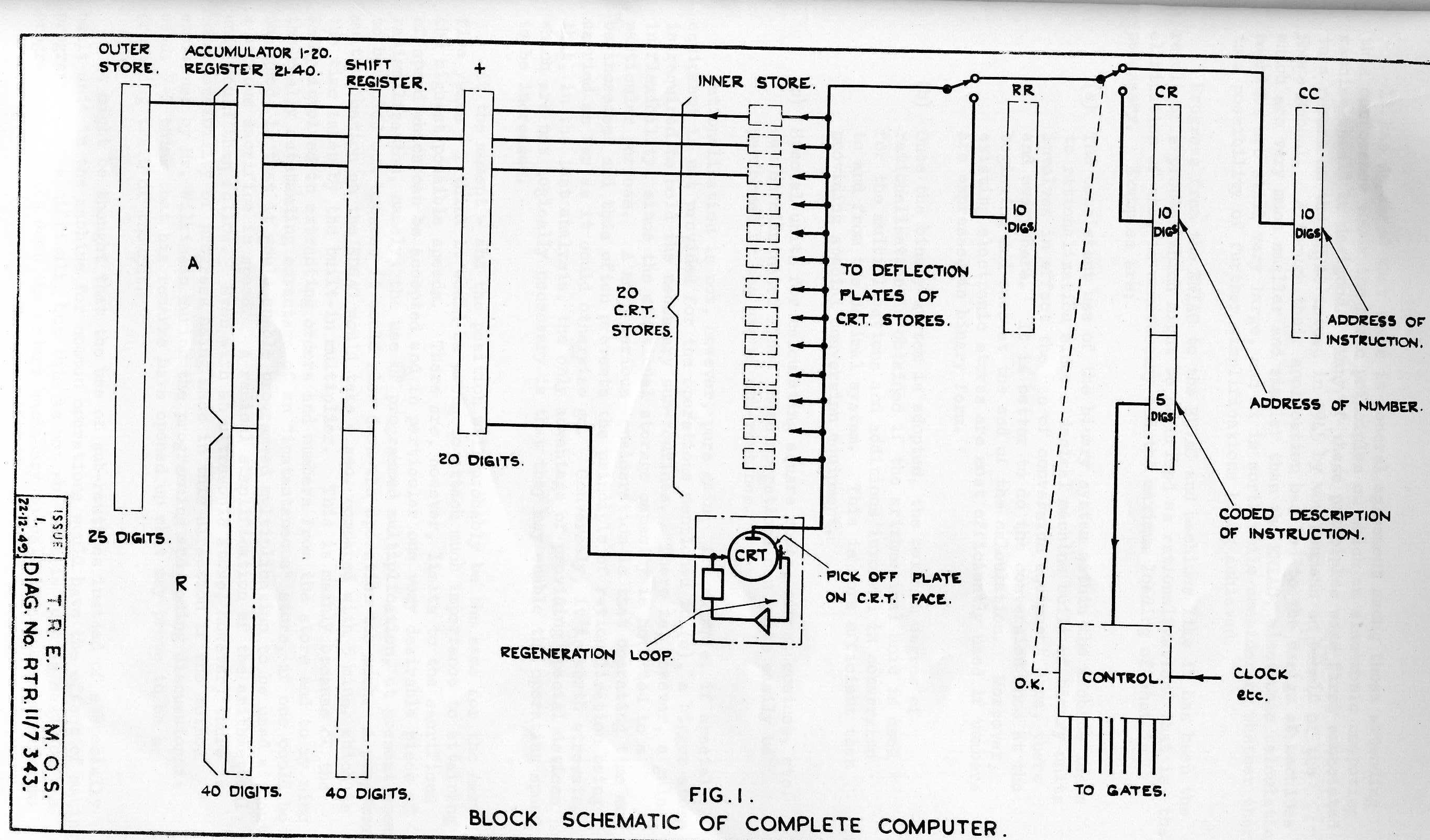
1.2. OS is the outer store which will use a magnetic drum and store instructions and results in coded decimal form using 25 write/read heads operating in parallel. A 26th head will provide a basic waveform which times the operation of the whole computer. Conversion to true binary form will be effected by the computer itself.
1.3. IS is the inner store consisting of 20 CRT's each storing one binary place for 1024 numbers.
1.4. R is a register to which a number can be transferred from IS for mathematical operations such as multiplication and division when two numbers are required simultaneously. This is not possible from the CRT store which can emit only one number at-a time.
1.5. A is the accumulator register similar to R but able to compute partial sums. This is done by sending the contents of A and IS simultaneously to +, the adding circuit.
1.6. The output of + is stored in SR, the Shift Register. To complete the accumulative operation the contents of SR are transferred to A. It is possible by means of SR to shift the contents of A and/or R by one binary place in the direction of either more or less significance.
1.7. The position of the CRT being used at any instant is determined by one of three registers RR, CR, or CC; the contents of the register being used at any instant being converted into analogue form as a deflection voltage.
1.8. RR is the Regeneration Register which is a scale-of-two counter of 10 stages counting regularly and so causing all digits of the CRT to be regenerated sequentially regardless of how or when they are used mathematically.
1.9. Alternating between moments of regeneration are moments of acting when instructions are either (a) being read or (b) being carried out. The deflection plates are then connected to CC and CR respectively.
1.10. CC the Control Counter contains the address of the Current Instruction, and this is the same thing as the number of the instruction in the list of instructions. There are 10 places in this register.
1.11. CR the Control Register contains the address of the number in IS being used (10 binary digits) and the type number (see below) of the instruction to be carried out (5 digits).
1.12. AC is the Arithmetic Control which accepts the instruction type in coded form from the 5 lower digits in CR, and causes the different transfer gates to operate in their correct sequence, the whole series being related to a basic clock waveform. Initially, multiplication and division will be programmed.
Let x be the address of a number in IS.
2.1. x → A : Clear accumulator and add the number located at x in IS to it.
2.2. -x → A :
2.3. A+x → A : Add the number located at x in the contents of accumulator and place it there.
2.4. A-x → A
2.5. A → x
2.6. x → R
2.7. L : Multiply contents of A and R by 2 leaving it there.
2.8. R : Divide contents of A and R by 2 leaving it there.
2.9. A and x → A : Compare A and x digit by digit and place a 1 in A for every place where a 1 occurs in A AND x. (Digital multiplication).
2.10. A and/or x → A : Compare A and x digit by digit and place a 1 in A for every place where a 1 occurs in A AND/OR x. (Boolean addition).
2.11. A or x → A : Compare A and x digit by digit and place a 1 in A for every place where a 1 occurs in A OR x. (Addition Mod.2.).
2.12. A + x → CR : Add contents of the accumulator to the instruction located at x and place the sum in CR.
2.13. x → CR : Write the contents of x in CR.
2.14. Test : Add most significant digit of A to CC. If A is negative so that this digit is 1 the routine will omit the next instruction 2.15. If A is positive the transfer instruction will be carried out.
2.15. x → CC : Transfer instruction. Write contents of x in CC and so leap to the beginning of a new sequence of instructions.
2.16. OS → x : Transfer contents of the 25 heads of OS to A and the 5 most significant places of R. Carry out decimal/binary conversion and place result in position x in IS.
2.17. x → OS : Carry out binary/decimal conversion of x placing results in A and 5 most significant places of R. Transfer to OS.
2.18. Stop
3.1. OS will contain on the 26th parallel track a waveform which may be regarded as a series of ones (See Fig.l). This waveform passes through a scale-of-two counter to form the Act/Regenerate Waveform (See Figg. 1). By means of this A/R waveform and an electronic switch the CRT plates are connected alternately to CR or CC for computing, purposes.
Instructions consist of single acts and take place during a single A/R period. It follows that the CRT plates are switched during act periods alternately to CR to obtain the address of a number and to CC for the address of an instruction. The switch for this purpose is controlled therefore by a second scale-of-two counter.
3.3 RR is a 10 stage binary counter capable of dealing with 1024 digits per CRT.
CC is a 10 stage binary counter with facilities for writing in a new number.
CR is a 15 place trigger register storing in its 10 most significant places the address of a number and in the next 5 places the instruction type. These 5 places are connected to AC to determine the sequence in which different gates open.
Note that RR, CR, and CC each have input or write points and output or read points.
3.3. IS consists of 20 CRT's. Each CRT has a regeneration feedback loop connecting the read point to the write point. Separate read and write gates are required at different points for each CRT. When writing, the regeneration or memory loop is broken.
3.4. The output of IS is switched to CC for instruction 2.15. The output is switch to CR for instruction 2.12. The output is switched to R for instruction 2.6. The output is switched to A in all other cases.
3.5. The output of IS is changed into its complement during instructions 2.2 and 2.4.
The various units of 1 digit machine have been completed. CRT storage for parallel use has been achieved. Checkable circuits have been completed for arithmetical, logical, and control operations. Magnetic storage has been achieved with a density of 6000 digits per square inch. The input and output organs for a complete machine have been built.
Mr. M.V. WILKES said:-
It has appeared that there is general agreement among those attending this conference about the basic principles on which an electronic computing machine 'should be designed. Many of these principles were first enunciated in a report on the EDVAC issued in 1945 by von Neumann on behalf of the Moore School. Although their application has led to the design of machines which are very much smaller and simpler than the ENIAC, electronic calculating machines are still very large, and it is worth while considering whether there is a possibility of further simplifications being achieved.
Progress from the ENIAC to the EDVAC and machines like it has been the result of a process which might be described as rationalization, that is, the elimination of what is unnecessary and the maximum loading of what is necessary. Examples are:
Rationalization is not, however, pure gain; for example, if special equipment is not provided for the operations mentioned in (c), a bigger store is required to hold the necessary sub-routines. There is, however, a gain in flexibility, since the additional storage capacity is not tied to a particular purpose. A more serious consideration is that operating time may be increased and this often prevents the principle of rationalization being carried as far as it could otherwise go. Conversely, it is worth stressing that, in the last analysis, the only advantage of providing special devices which are not logically necessary is that they may enable the operating speed to be increased.
At the moment - and the position will probably be the same for the next five years - I think it would be wrong to attach much importance to attaining the highest possible speeds. There are, however, limits to the sacrifices of speed which can be accepted and in particular one very desirable piece of rationalisation, namely, the use of programmed multiplication, at present seems to be ruled out because it would slow down the operation too much. A programmed multiplication on the EDSAC would take ½ sec. compared with 5 mins. which is the time taken by the built-in multiplier. This is mainly because of the delay involved in extracting orders and numbers from the store and to my mind the really outstanding advantage of an instantaneous store, if one could be designed, is that it would enable programmed multiplication to be used without a serious sacrifice in speed. A radical simplification of the arithmetical unit would then follow. Even with an ultrasonic store, however, there is some possibility of progress being made in this direction if the method explained by Mr. Wilkinson during the programming and coding discussion is used. I think that his remarks have opened up what may prove to be a promising train of thought.
It might be thought that the use of sub-routines instead of a specially built unit in the machine for common operations would have the effect of making programming more difficult, but this is not so. It is just as easy for the programmer to write down the orders necessary to call in a sub-routine as to write down the orders necessary to bring the special unit into action. There is, in fact, a close similarity between a sub-routine and a piece of equipment built to perform the same function. One can either hire a mathematician to build a sub-routine, or an engineer to build a piece of equipment. In either case the work is done once for all; the only difference is that the engineer's work will require maintenance whereas the mathematician's will not. From the point of view of the programmer there is little to choose.
If the store is to be used as efficiently as possible it is desirable that orders and numbers should be of the same length. The address of an order can be reduced to a minimum by making sure that the high-speed store is no larger than is required, having regard to the time taken to transfer blocks of numbers from the auxiliary store. This line of argument leads to a word length which is rather short for the representation of numbers and I suggest that perhaps the most efficient way to design a machine, particularly a parallel machine, is to have a basic word length of 15 or 20 binary digits and to regard double-length or even multi-length arithmetic as standard practice in computing operations. For the counting and control operations which form the major part of any programme, single length arithmetic is quite adequate even with a short word length.
It is sometimes possible to make progress by looking at a problem in a new light and I would like to put forward an unusual way of regarding a calculating machine. It is customary to divide a machine into a store, a control unit, and an arithmetical unit. If the machine is viewed as a computing device this is logical, but if it is viewed purely as a machine an alternative analysis is to divide it into storage elements and coding elements.
A schematic diagram for a possible machine would then be as follows:
The machine is supposed to operate in a succession of beats during each of which the whole of the information in the store is passed into the coder, translated into a new form, and then returned to the store.
For purposes of illustration, I will consider a simple machine using words of three binary digits each and having 8 storage locations numbered from 0 to 7. A programme for the calculation of a + b = c, where a = 010, and b = 101 will be given. The order code will be supposed to consist of two orders as follows:
1 n : transfer the number in storage location n to storage location 7, adding it to the number already there;
0 n : transfer the number in storage location 7 to storage location n to replace what was there before.
It is to be noted that n is a two digit binary number and that storage location 7 plays the part of an accumulator.
Initially it is supposed that storage location 0 contains a and that storage location 1 contains b. a + b when calculated is placed in storage location 2. The programme consists of three orders placed in storage locations 3, 4, and 5 as follows:
3	100
4   101
5   010
The contents of the store at each beat of the machine are given below. Storage location 6 plays the same role as the sequence control tank in the EDSAC.
                         (a)   (b)           o r d e r s     SCT   Acc
No of storage location    0     1     2     3     4     5     6     7
                         010   101   000   100   101   010   011   000
Contents of              010   101   000   100   101   010   100   010
  store                  010   101   000   100   101   010   101   111
                         010   101   111   100   101   010   110   000
The contents of the store at each stage have been divided up into storage locations and labelled as orders or numbers in conformity with the usual practice. The coder, however, treats the contents of the store as one long number and does not distinguish the meanings of the individual digits; it is so constructed that for example, whenever the number 010101000100101010011000 is presented to it, it sends out the number 010101000100101010100010. If this were done along the lines of a code book there would need to be the equivalent of a large number of entries - as many as 27 in the case of this simple machine. The control and arithmetical sections of an ordinary machine can be regarded as a coder in which advantage is taken of the fact that coding is performed according to a system rather than according to an arbitrarily laid down code. The question to be considered is whether conventional methods of designing this coder are the most efficient which could be evolved.
Whether the method of regarding the operation of a computing machine which I have indicated will ever prove to be of use I do not know.
Prof. NEWMAN said that Mr. WILKES had, in the latter part of his remarks, come very near to using a method already used by Dr. TURING in discussing the classes of problems which can in principle be solved by means of a machine.
Mr W.S. ELLIOTT said, I should like first to make some comments on the paper by Dr. Huskey which was read yesterday. A project which was not mentioned is that of Professor Morton at the University of California, Berkeley, California. This project aims at designing a small high-speed computer which could be copies by University Laboratories. In March, I saw a model of the magnetic store which was made by winding a helix of tape on a bakelite drum. The spacing along the tape was 80 tracks to the inch and the digits were spaced at 10 to the inch.
I should also like to mention some of the views of Professor Aiken.
Professor Aiken points out that his Mark III calculator is the slowest electronic machine in the World, taking 12½ milliseconds for multiplications. Even so, it will invert a matrix of order 50 in 90 minutes. It is 300 or 400 times faster than the Mark I calculator and six men are kept busy preparing problems for the Mark I. If all the machines now being built are completed there would not be the mathematicians to run them. When the Mark IV is finished at Harvard it will be slower than the Mark III. A further point about speed which Professor Aiken emphasises is that the resultant speed of getting problems out of a machine may be determined much more by the frequency of occurrence of errors than by the inherent operating speed. Professor Aiken made some calculations in which by multiplying an inherent operating speed by 10 and keeping the same error rate there is very little improvement in overall speed but keeping the same inherent speed and reducing the error rate by a factor of 10, the overall speed is multiplied by 3.
Easing the work of mathematicians in coding problems is another point on which Professor Aiken feels strongly. Quoting him, there is only one way to lick coding and that is to eliminate it. Problems will be coded for Mark III by giving the mathematicians a mathematical button board which understands normal mathematical language and which automatically prepares all the necessary orders and calls up the sub-routines for the machine.
I should now like to describe some of our work at Borehamwood.
We are developing components for a fast series working machine. The logical arrangement and programming of this machine will be less complicated than that of the machines which have been described during the Conference, but a short mention of what we are doing may be of interest.
On Thursday, Professor Williams mentioned the use of anticipating pulse in cathode-ray tube storage. We have measured the amplitude of the excavation and anticipation-pulses at varying writing speed and have found that as writing speed increases, the anticipation-pulse amplitude goes up whereas the excavation pulse amplitude falls off. At these fast writing speeds, the anticipation time is, of course, small and we have to minimise the delay in any arithmetic unit inserted in the regeneration loop. We have an adding circuit with a delay of less than one tenth microsecond which has operated in the regeneration loop of a store (that is, we have run the store as an accumulator) at a digit rate of over half a megacycle per second.
I described our photographic permanent and semi-permanent storage and the similar input-output methods yesterday. I should add that in connection with the Binary-Brunsviga machine for preparing input film we are making a decimal-binary converter to feed the binary desk machine and for the output of the high-speed machine we are making a binary-decimal converter and typewriter.
We have a fast multiplier using circuitry only and making no use of the working store until the precise or rounded-off product is sent to the store. The multiplier takes input numbers a and b in the same number time and forms a rounded-off product ab. The multiplicand pulse sequence passes down a delay ladder, that is a chain of digit-time delays, and outputs from the successive delays are selected by gates set by the multiplier number. The gate outputs are summed in a network of adding circuits of the form known as the wiffle tree. In a system using n-digit numbers there are (n-1) adding circuits which may call for a large number of valves. For this purpose we have made quite a small adding circuit and have built up a high-speed multiplier for 16-digit numbers. A digit slip is used after each adder in the tree and the number of digit slips in the multiplier is equal to the number of digit times between successive numbers in the computer rhythm. The basic multiplier has been operated successfully with positive numbers and is now being modified to handle both positive numbers and negative numbers (as complements).
Brigadier G.H. HINDS expressed gratitude to Dr. Wilkes and the audience for the interesting Conference, and continued:-
I speak as an outsider - a civil servant - a user of science. I am told that this new instrument will open new fields of scientific accomplishment - that the mathematical physicist can now do things he could never do before, and that these include aero dynamics, thermo-dynamics, and the stressing of structures. I want to see Ministry Establishments (which are not all warlike) equipped with these facilities, and I ask Where can I lay my hands on a machine?
During this Conference I have formed the definite impression that there is no machine at present available for use. Many people are making and designing machines in this country in order to learn how to make or use such machines. The Ministry of Supply has no control over institutions such as Universities, and I hope that we shall, before long, build a machine for ourselves. At the moment 1 am looking for the best advice I can get on the many questions that arise. Ought we to build one machine or more? Would it be more economic to have several, or to have one which can be used by all establishments? What would the cost be?
If the cost is relatively small it would cut out the need for continuous working.
But when do we ask for a machine? When will a design be stabilised? Would it be advisable to build a general purpose machine? I also want to know what capacity should be specified and whether it should be a relay machine or electronic. Reliability being of vital importance, the answer seems to depend on the relative reliability of the two types, but are records being kept? Do we know what the relative reliability is for the Manchester and Birkbeck College machines? Is there statistical information over a period? Other points are, the best form of storage - whether we need internal checking - besides a number of mathematical queries. For instance, should we go in for the decimal or binary scale - and series or parallel working?
The programming depends on the type of machine, but who are the programmers to be? Will it be the job of the High Priests of the machine? Will Physicists and Engineers with problems do their own? or will there be a special intermediate class? This question of programming raises another important point. If Establishments have to do it, can they learn Programming in general, or must they wait until they know what kind of machine they are likely to use?
The question of standardisation of nomenclature has been raised, but Standardisation means different things for different men. Today it has become a fetish; but if there is a real diversity of ideas some reconciliation is essential, and if the diversity is only faddism it may be better to clear it up. If there is any danger of misunderstanding we ought to clear it up, but I hope that we can leave it to the Universities. If the Ministry can help to co-ordinate nomenclature we would be willing to do so, but I hope it will be unnecessary.
Mr. T.R. THOMPSON of J. Lyons & Co. said his firm had considered the use of an electronic machine for clerical purposes in order to relieve the heavy load which such work entailed at present. As a machine could not be bought they had decided to build one and he expected that it would cost between £20,000 and £100,000.
Mr. MACHIN said that machines would have to be assessed on a commercial basis by working out what the cost of their services would have to be in order to pay a dividend after taking into account, cost of machine, depreciation, maintenance costs, running costs, etc.
Mr. D.M. Mackay said:-
We have several times encountered the idea of the interchangeability of time and complexity of apparatus, in reckoning up the merits of different techniques. This is an example of the kind of judgment which can be quite precisely formulated in terms of a general theory of Information. Omitting details, this may be said to make possible a quantitative assessment of the upper limit to the information capacity of a method occupying a given space-time tract and involving a given energy-consumption. Moreover it points to certain general principles on which, say, energy may be bartered for speed (i.e. effective bandwidth) or compactness. Thus for example many machines working at moderate speeds provide in each pulse a large amount of information (in this technical sense) which is wasted. What we may call semantic efficiency could theoretically be increased either by widening bandwidths and increasing pulse rate (i.e. increasing the multiplicity of the information-space) or by reducing power consumption, or by extracting more than one unit of information from each pulse.
Assuming that other considerations fix the maximum speed of operation, the second alternative is not very attractive, if only because the power consumption of most elements is fixed within an order of magnitude. (At the same time it has been mentioned that at speeds of the order of 10 M c/s valves of higher power have to be employed to charge the stray capacitances; and a lower limit is set to the latter partly by the relationship between the size of an electronic element and its current-capacity, and partly by considerations of physical stability and the like.)
From the view point of Information theory then the suggestion arises that, other things being equal, a slower machine ought to discriminate between more than two levels, or other characteristics, of each pulse. How the usual argument in favour of the scale of 2 is based on the assumption that cost is proportional to the total number of possible discrete states, and is reinforced by the assumption that electronic relays are reliable only as 2-state elements. Now that circuit technique is making this assumption less justifiable, it might be worth while to examine the advantages of higher semantic efficiency, and perhaps to reconsider the scale of values on which a choice of method should be based.
At a still more primitive level, information theory appears to have some relevance to the problem of division of labour between digital and continuous-variable techniques. It is possible to distinguish between two aspects of information, roughly corresponding to the form and content of a scientific statement reduced to its simplest terms. The first is concerned with structure, the second with magnitude. The first is particularly suited to digital representation, and the second to continuous - variable treatment. Now it is true that all communicable statements can in theory be broken down ultimately into a pattern of two-valued elements; but this is not necessarily the most appropriate representation, any more than a Fourier series is necessarily the most appropriate way of describing a given waveform.
Most digital computers represent magnitude as a two-valued concept, or indirectly in terms of structure; but as Mr, Elliott has mentioned there are some tasks in which a continuous representation of magnitude finds a useful place alongside digital techniques, and which are better performed when an intelligent use is made of both aspects of information in the kind of way that a human computer does.
Similar considerations indicate that in some fields definite advantages should be obtainable from the adoption of continuous-variable methods in preference to digital; but that is another story. What I wish to suggest is that in many matters of current debate subjective preferences could be usefully supplemented by quantitative judgments on these lines, and that the philosophy of machines designed to manipulate general information may find some useful guidance in general information theory.
Major F.A.N. HITCH drew attention to the distinction between binary and decimal machines by comparing two forms of adder circuits both based on the representation of digits by various frequencies in pulses of constant duration, and said,
For the sake of simplicity I have based these examples on the possibility of building a slow speed serial machine in which the most rapid form of storage is that afforded by magnetic recording devices.
Diagram I indicates a crude form of adder in which the digits of the two addends are selected in parallel sequences from the magnetic stores S1 and S2 by means of the two groups of narrow band pass filters F1 and F2 and caused to energise a series of partial sum lines P by means of a matrix of 2 elements.
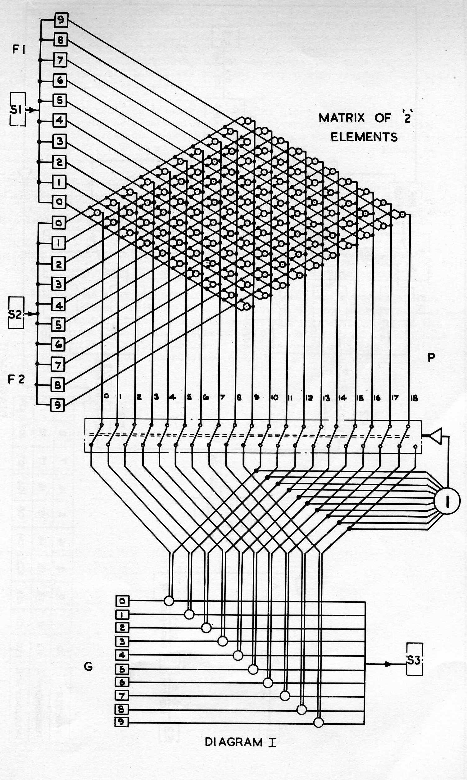
Ten frequency generators G provide the frequencies needed to produce the digits for the product, and their outputs are gated into the product magnetic store S3 in accordance with the signals received over two alternative sets of connections to the partial sum lines P: the multipole switch giving the alternative connections to deal with the carry problem is shown operated by the output of a 1 element delayed by a unit delay.
Apart from the single lines connected to S1, S2 and S3 and those running from the generators to the gates, the presence or absence of a digit is denoted by the existence or lack of a signal on a line allotted to that digit. The form the signals take on these lines is of no consequence and as the only criterion that need be applied to any line when considering the operation of the machine is that of the presence or absence of a signal, the operation can best be thought of as a binary process.
Diagram II shows a technique for adding which I believe has not been previously proposed and which can most easily be thought of as operating on a decimal rather than a binary system.
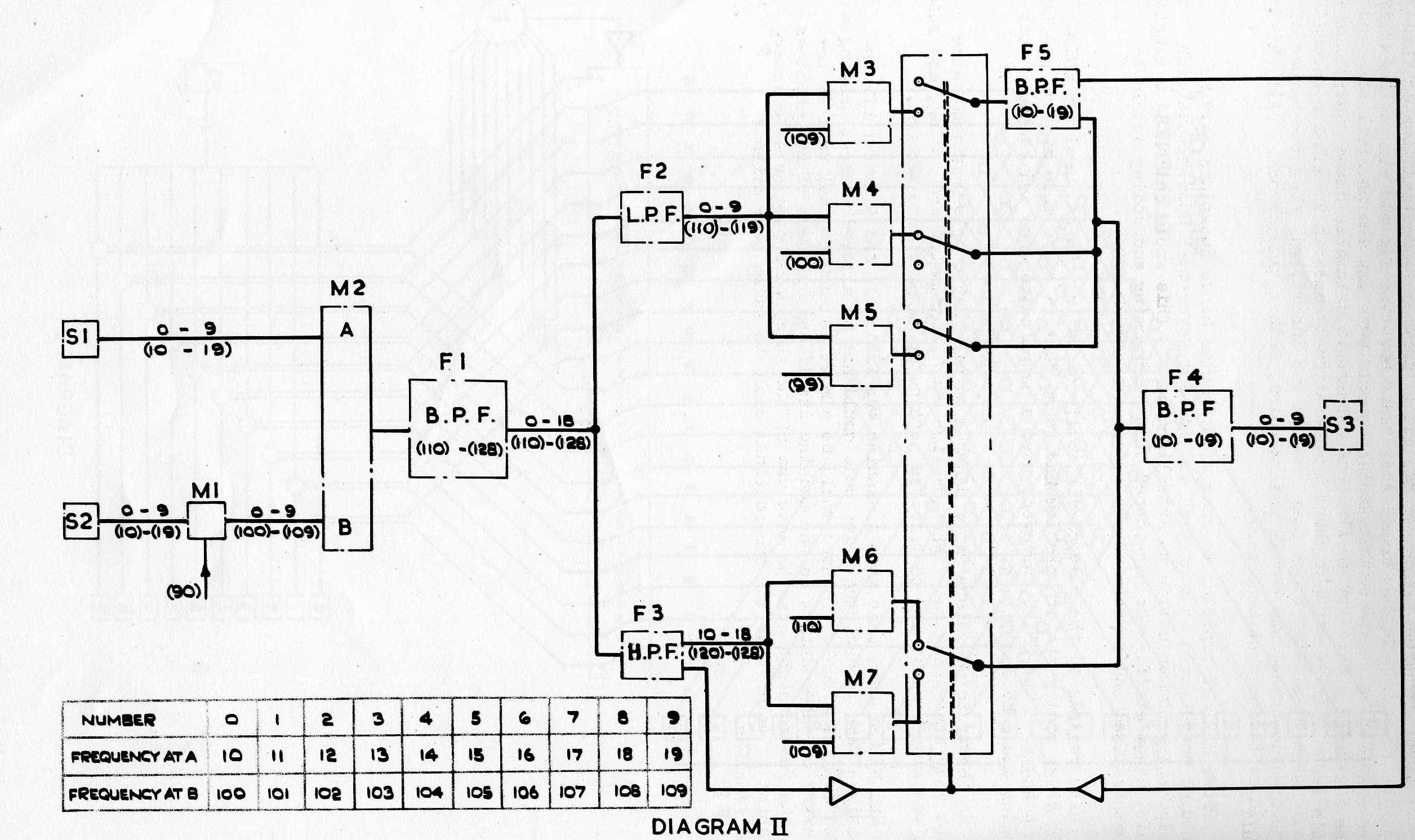
The adder makes extensive use of modulators for the generation of sidebands and although the realisation of the processes indicated might demand the use of a carrier system, only the modulation frequencies have been shown on the Diagram.
The digits of the addends are taken in parallel sequences from the magnetic stores S1 and S2 in which the digits 0 to 9 are represented by frequencies proportional to 10 to 19 respectively. The output from S2 modulates a frequency proportional to 90 in a modulator M1 and the outputs from S1 and M1 are mixed in M2 and generate upper sideband frequencies proportional to 110 to 128, corresponding to the partial sums of (0 + 0) to (9 + 9); the unwanted modulation products are suppressed by the filter F1. Filters F2 and F3 divide these frequencies into two bands, (110 - 119) representing the digits 0 to 9 and (120 - 128) representing the numbers 10 to 18.
Except in the case of the output of F2 representing a 9, the outputs of F2 and F3 are demodulated with frequencies proportional to 100 and 110 respectively in the absence of a previous carry, and by frequencies proportional to 99 and 109 respectively if a previous carry remains; the need for a carry is associated with the existence of an output from F3. The unwanted frequencies are suppressed by the filter F4 and the digits from 0 to 9 are recorded on S3 as frequencies proportional to 10 to 19.
In the special case of a 9 appearing at the output of F2, the lower sideband frequencies obtained from M3, M4 and M5 are proportional to 10, 19 and 20 respectively. In the absence of a previous carry, the carry switch only connects M4 to F4 and so a 9 is recorded. If a previous carry remains both M3 and M5 are connected to F4, but as F4 discriminates against the frequency from M5 proportional to 20, only that proportional to 10 from M3 is passed to S3 and a 0 is recorded. The special new carry which this last case must give is associated with the existence of an output from F5.
Apart from the control of the unit carry, it is thought that the representation of decimal digits by the code suggested makes any attempt to regard the apparatus as a binary system quite unrealistic.
Mr. COLEBROOKE said that his position was the same as that of Brigadier Hinds. He thought we were at the beginning of a new and exciting adventure, and it was most important to realise that the early months were a period for operational research so that we may get to know the potentialities of this new instrument. He considered that there were two aspects viz. mathematical and engineering. The mathematicians should work out the possibilities and the engineers should try to find the answers to Brigadier Hinds' questions. This would only be brought about by operational research in which a record would be kept of what broke down, how it was identified, what the nature of the breakdown was, and how it was remedied, with a time record. All this would be tedious but necessary.
Prof. HARTREE replying to some of Brigadier Hinds questions said he thought there would be a central machine for Government Departments with Teleprinter Communication to Establishments. This would only need a single maintenance staff. He considered that programming and coding should be decentralised and deprecated making these a closed art.
With regards to the alleged difficulty of coding, he had used the ENIAC and after coding the 4th problem had found that he could code his own problem in 4 hours. The ENIAC, however, used a complicated code and he hoped that coding would be simplified.
In answer to questions Prof. HARTREE agreed that people must make sure that they are asking the right question when programming and coding, and said it was always necessary to take the particular machine into account.
Mr. WILKES said that when a machine was finished, and a number of subroutines were in use, the order code could not be altered without causing a good deal of trouble. There would be almost as much capital sunk in the library of sub-routines as the machine itself and builders of new machines in the future might wish to make use of the same order code as an existing machine in order that the sub-routines could be taken over without modification.
