
The use of the magnetic properties of the ferro-magnetic materials for the storage of audio-frequency signals has found very wide application. It is therefore a natural development that these same storage properties be used for the storage of binary data in the permanent memory of a binary computer. The requirements of the storage medium of a permanent memory are that it shall record the two states of a binary digit and that this record may be consulted at will with no deterioration of the record during the reading process. The stored information must also be open to correction or renewal at any subsequent time.
We may for the purposes of illustration of the general principles of a magnetic storage system, divide the magnetic medium into cells each having a finite area. Each of these cells must by reason of its magnetic configuration be capable of defining either state of a binary digit. It is also desirable that the state may be readily interchangeable by a simple process. The state of any cell as represented by its state of magnetisation is a purely static form of storage. To convert this information into a dynamic form we must move the magnetic medium relative to a pick-up head. The pickup head will either be in contact or in very close proximity to the moving magnetic medium. The voltage developed in the windings associated with the head will have a wave-form approximating to the time and space derivative of the stored flux pattern which must be of such a nature as to give clear indication of the state of the digit cell which is at that moment passing the pickup head. The speed at which this information is gained is dependent on the rate of passage of the magnetic medium past the head. The means of loading the information into the appropriate cells may take the same form as the reading process, the magnetic flux produced in the recording head will establish the desired magnetic pattern in the cells. The speed of loading is again dependent on the rate of passage of the material past the head. It is obviously desirable to store as many digits to the inch as possible, the limit at present is set by the construction of the recording and reading heads and densities ranging between 60 and 160 digits to the inch are obtained with systems already in existence.
The first problem of magnetic storage is the representation of digits on a magnetic medium, the methods used being common to all systems whether wire, tape or drum. There are various methods of digital representation in existence, these various systems differing in the magnetic pattern used to define the digit state in each unit cell of the magnetic record. The first system Which I shall call the dipole method has been used at Princeton in their preliminary research into the capabilities of drum storage. Considering Fig. la, plots I and II represent the space distribution of magnetic flux linearly along the plane in the direction of motion of the magnetic material. Thus in the initial state the material is demagnetized for its whole length. Each digit cell has a length 1 and we require to store the number 11101000 serially along these cells. This is done by saturating a small length s at the beginning of each cell either to a polarity A or B, thus for a 1 the segment is saturated to a level A and for a 0 it is saturated to a level B. The resultant flux distribution for the specimen number is of the form shown in plot 2. Each digit has a discrete identification. To recover the information the medium is moved past a pick-up head, the magnetic flux will take the low reluctance path of the head and induce in its associated windings a wave-form as shown in plot 3. This plot has the induced voltage for its ordinate and time abscissa. The tine t being the time taken for the length 1 of magnetic medium to pass the head. We can see from the form of this wave-form that the different states of 1 and 0 produce readily interpretable signals, thus a 1 gives a positive peak followed by a negative while a 0 produces a negative followed by a positive peak. The limit set to the minimum value of 1 is due to the finite width of the flux produced by the recording head and the effective width for pick-up in the reading head. Densities up to 120 digits per inch have been obtained. The process of re-writing is simple, thus in the case of changing a 0 into a 1 the flux appropriate to the 1 will saturate the selected segment into the appropriate direction, its previous state being irrelevant. There is one defect of the system in that the position of each cell must be known to a high degree of accuracy so that the new information may be exactly superimposed on the old. If the necessary accuracy cannot be obtained then the only solution is to completely erase the old information before re-writing.
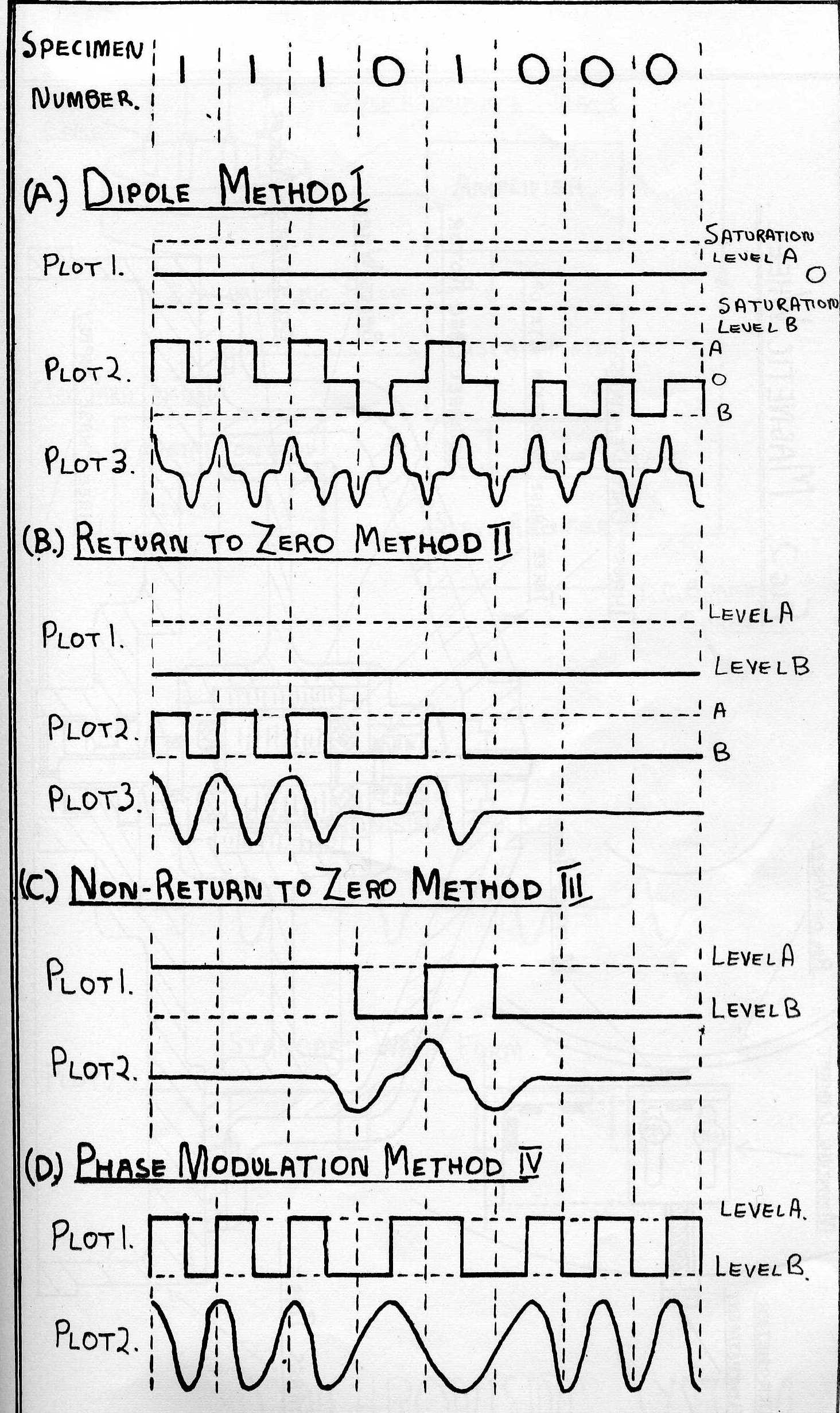
The second method, which is known as the return to zero method, is in principle similar to the previous one where each digit has a definite representation, it differs, however, in that there is no non-magnetised region in any digit cell. Initially the magnetic medium is saturated to the level B which represents the state 0 in each cell. To inscribe a 1 in any cell a segment of length 0 at the beginning of the cell is saturated to the level A. The flux pattern for the specimen number is shown in Fig.1B plot 2, plot 1 representing the initial state. The reading head induced voltage is shown in plot 3, a 1 being indicated by a +ve and -ve peak while a 0 has a zero level. To re-write new information the new configuration can be directly| superimposed on the old as the whole of the magnetic surface is saturated in one state or the other and previous conditions do not affect the new.
The third method which is known as the non-return to zero method employs a new principle in that during the reading process there is no discrete indication of the contents of each cell but only where there is a difference in contents of adjacent cells. This is achieved by the flux pattern shown in Fig.1B plot 1 where a 0 is represented by full saturation of the whole cell to a level B while for a 1 the cell is saturated to a level A. Plot 2 represents the pick-up voltage where a positive pulse denotes the beginning of a train of 1's and a negative pulse the beginning of a train of 0's. Comparing this wave-form with its counterparts in the two previous cases we see that the maximum frequency of the wave-form in this case is half that of the others and that the shortest region of uni-directional magnetisation is twice as long as in the previous cases. It therefore follows that we can pack twice as many digits to the inch as in the other cases. Densities up to 150 to the inch have been obtained employing this method.
The fourth system which I shall call the phase modulation system has a flux distribution as shown in plot 1 Fig.1D. There a 1 is represented by a cell with its first half saturated to a level A and its second half to a level B, while for a 0 the order is reversed and the first half is at level B while its second half is at level A. Plot 2 represents the pick-up voltage obtained, which is built up of a sine-wave with a frequency 1/t for a train of continuous digits and cycles of frequency 1/2t at change-over points. The sine-wave has an inverse phase for a 0 and a 1. Thus for a 1 the negative peak occurs in the middle of the digit period while for a 0 the positive peak occurs at this instant. This system has the advantage that considerable interference between adjacent cells at the pick-up head can be tolerated and that also the writing current required, to produce the flux distribution is of a nearly balanced nature and so can be passed through transformers.
The digit packing densities quoted for the various systems are by no means a fair basis of comparison between them for other factors such as head design and properties of the magnetic material employed greatly influence this quantity. It is, however, inherent in the principle of the non-return to zero case that packing densities double that of any other system can be obtained under the same conditions of head design and magnetic material. From our own experience with the fourth method of digital representation and using nickel as the recording medium with heads having .00025" gaps it seems possible that densities of 160 digits per inch are obtainable.
It is from this point that the various systems of magnetic storage diverge into two classes, one of rotating systems such as drums and the other of magnetic tape and wire. We shall define a drum system as one in which one storage track on the periphery of the drum contains a discrete number of digits. The number of tracks on the peripheral surface of the drum being dependent on the width of this surface and the number of tracks it is possible to place in an inch. The access time to any particular digit in a track will depend on the relative position of the drum to the pick-up head when that digit is demanded but will in the limit only equal the period of revolution of the drum. With the high speeds of rotation which it is possible to achieve this can be made small. The access time may be reduced by providing several reading heads around the periphery of the drum. Apart from particular applications the added complexity of selection required by this system makes it unpractical. The selection of tracks of which there may be a great many, can be treated by usual electronic or relay selection mechanisms and the access time will be that customary to these two types of selection. The drum as described is particularly suited for the storage of data for a parallel machine as the forty or so tracks required for the storage of each digit of a number are easily accommodated on a drum.
With the tape system the number of serial digits is undefined, depending on the length of tape employed, it also being possible to place several tracks along the width of the tape. With the wire system the storage is purely serial. The most obvious difference between the two classes is one of access time to any particular digit. Thus in the drum system the maximum access time is the period of revolution of the drum, whereas in the tape and wire system it is the time taken to run through the whole length of tape. The difference factor here is large as the rotational speed of a drum will be many times greater than the speed of tape through the scanning apparatus.
Using a drum we can attain a small access time to any digit and with the high rotational speeds attainable it is possible to match a magnetic drum storage system with a high speed computer either feeding the machine directly or acting as a supplementary store to the high-speed store. To qualify this statement we must further classify the possible applications of drums into what I shall call the synchronous, self-synchronous and non-synchronous classes. The synchronous class of drums is one in which the drum revolves at a speed in synchronism with the clock of the computer. In this case the problems of digital selection are relatively simple, the drum being in exact phase with the machine the position of any digit in a track will be automatically known. The self-synchronous class covers the case of drums which act as the clock for the rest of the computer the machine being run in synchronism with the drum. This system has the disadvantage in that never more than one drum of this class can be associated with a machine whereas in the first class it is possible to have as many drums as required, so that the storage capacity may be extended to any limit. The non-synchronous class covers the case when there is no frequency connection between computer and drum so that all transferred data has to take place through the agency of a buffer store.
Our work at Manchester has been concerned with drums of the synchronous class and I shall outline the application of this system and the results obtained. The drum is designed to work in conjunction with a high-speed electrostatic store which has a capacity of 2560 digits. The drum transfers digits at the normal machine rate of 1 digit per 10 m.secs. Each track of the drum stores the contents of one complete high-speed store, i.e. 2560 digits. To do this a wheel of diameter 12" is used which gives a periphery of 36" with a peripheral surface of 2" depth giving in all a storage surface of 72 sq.ins. With 2560 digits in the 36" a packing density of 80 digits to the inch is used at present though experiments have indicated that this density may be doubled and a new drum is in the course of construction which will have a diameter of 6" and store the same number of digits per track. To enable the stored digits to be transferred at the rate of one every 10 m.secs, the wheel is run at 2080 r.p.m., the peripheral speed being of the order of 90 m.p.h.
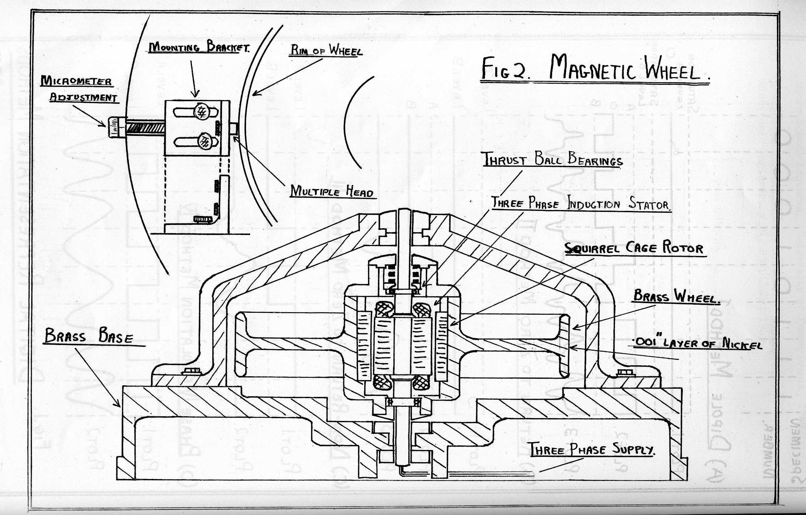
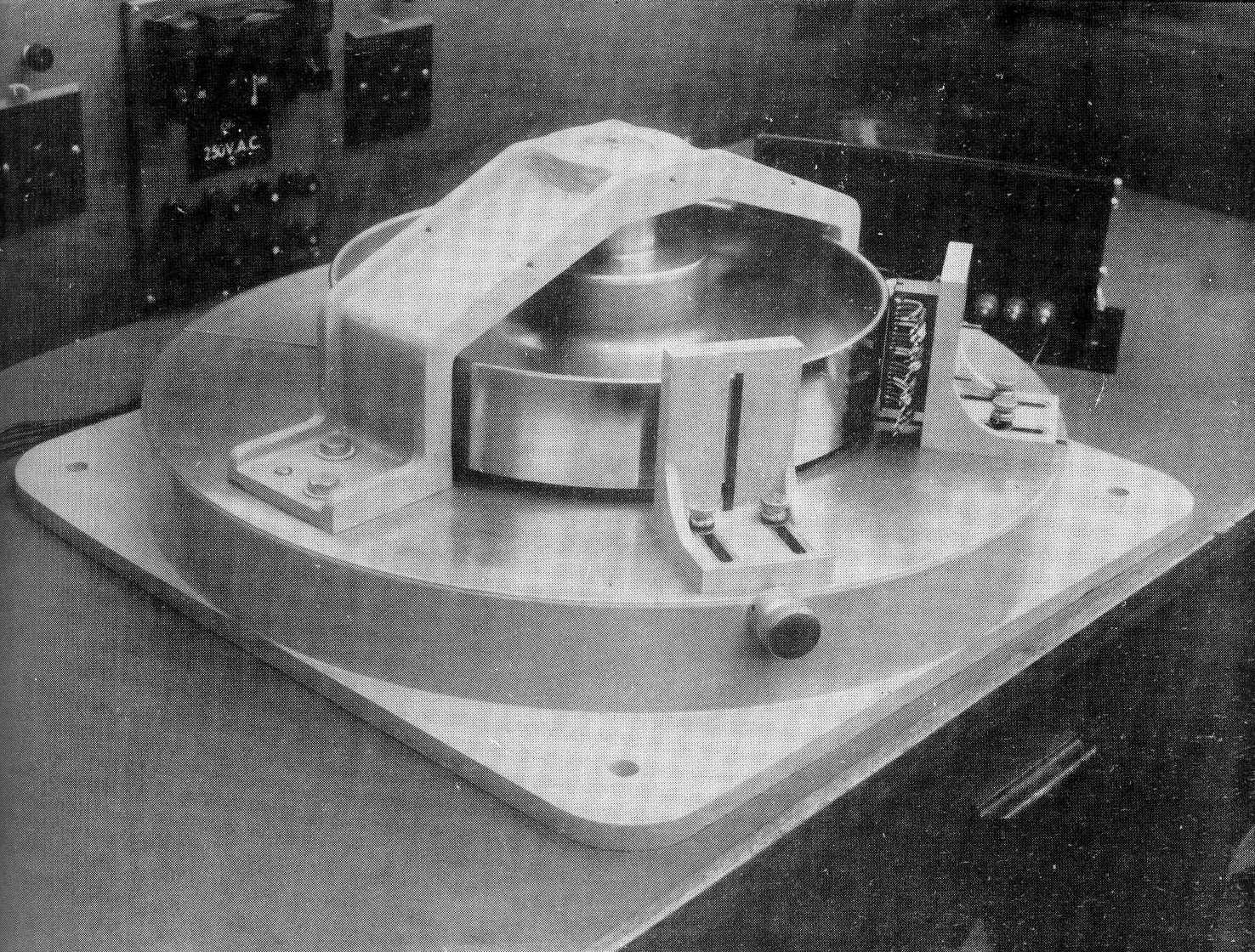
The wheel in use at present is shown in Fig.2 and photograph 1. The wheel itself is cast in brass and is of 11.5" diameter. The rim is of 2" width and the peripheral surface has a plated layer of nickel about .001" thick. The wheel is spun horizontally about a 3 phase induction motor stator as shown, the squirrel-cage rotor being secured to the wheel which spins on the two sets of bearings shown. The synchronous speed of this motor is 3000 rpm. and the required running speed of 2080 rpm., is obtained by braking the wheel with a set of eight relay coils which are mounted above the horizontal surface of the wheel. The braking-current through these coils is controlled by a servo-mechanism which is itself controlled by the clock of the computer. The heads are mounted in right-angle brackets, which are bolted to the massive base plate of the wheel and may be approached to the surface of the wheel by a micrometer drive.
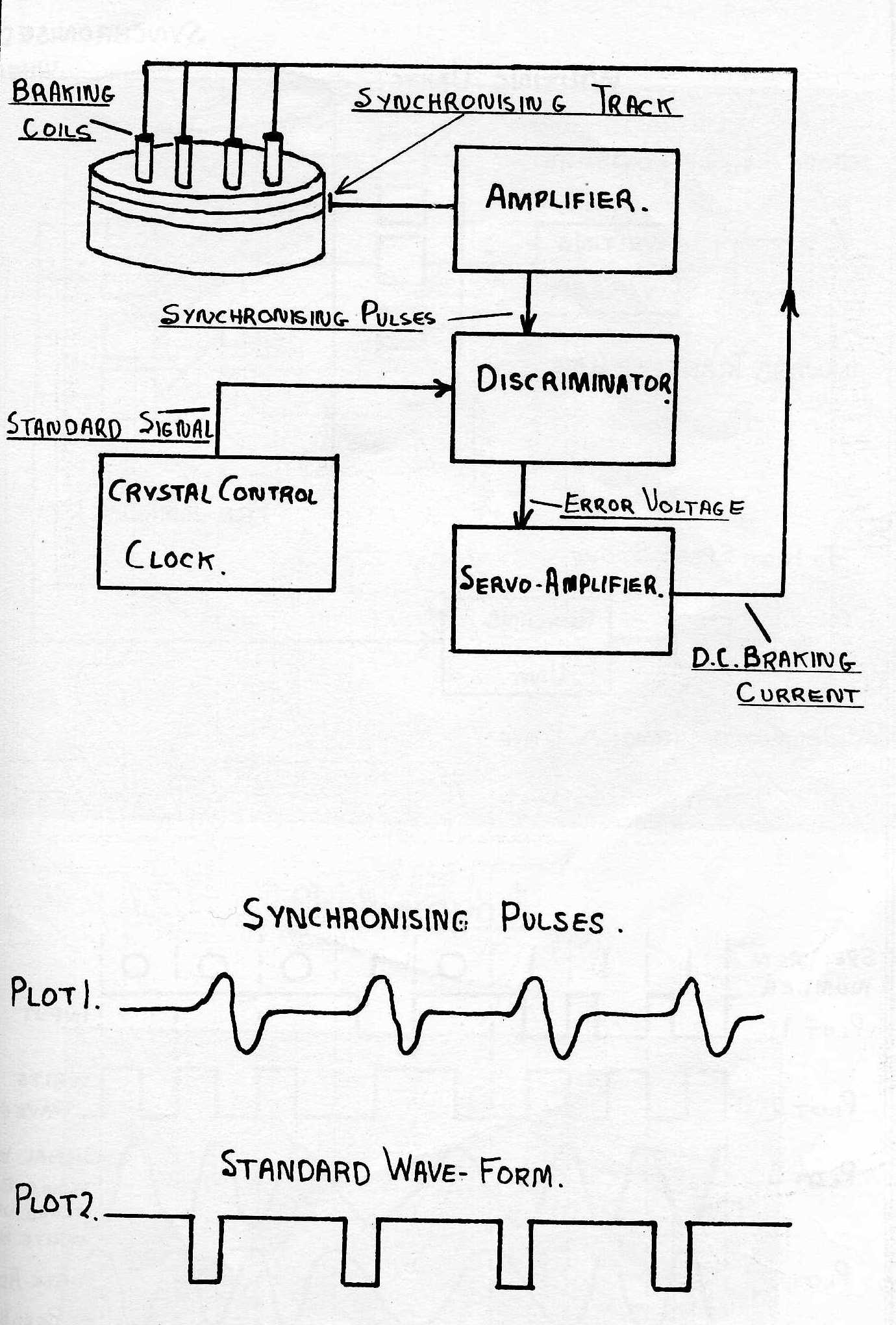
The synchronising system is shown in Fig.3. One track on the wheel is devoted to a set of 64 pulses which are recorded equidistantly around the periphery. These pulses are picked up through the reading head and fed to a four stage amplifier which feeds the output pulses of about 20 volts amplitude to the discriminator, The discriminator is also fed with a standard wave-form from the clock of the computer and is of the form shown in plot 2. The positive peaks of the synchronizing pulses shown in plot 1 are then balanced about the positive going edge of the standard wave-form and any misalignment produces a D.C. voltage proportional, to the error. This D.C. voltage is fed into the servo-amplifier which effectively produces a D.C. current in the braking coils proportional to the input signal. We have therefore a closed servo loop in which the error signal is obtained by comparing the relative positions of a wave-form obtained from the wheel and a standard wave-form from the computer. The action of the servo may be illustrated by assuming that the wheel is tending to run too fast then there will be misalignment between the two sets of wave-forms which will produce an error signal in the discriminator, this feeds the servo-amplifier which in turn increases the braking current in the braking coils and the tendency to increase speed is automatically compensated. The accuracy of synchronism required may be calculated from the requirements of the wheel. Thus there are to be 2560 digits in the 36" which gives a digit cell length of .012" the position of each cell must be constant to the order of .001" if the selection, reading and writing mechanisms are to function. Therefore the accuracy required is .001" in 36", i.e. an accuracy of 1 in 36,000. This degree of accuracy has been achieved with the present system which has now been functioning reliably, for two or three months.
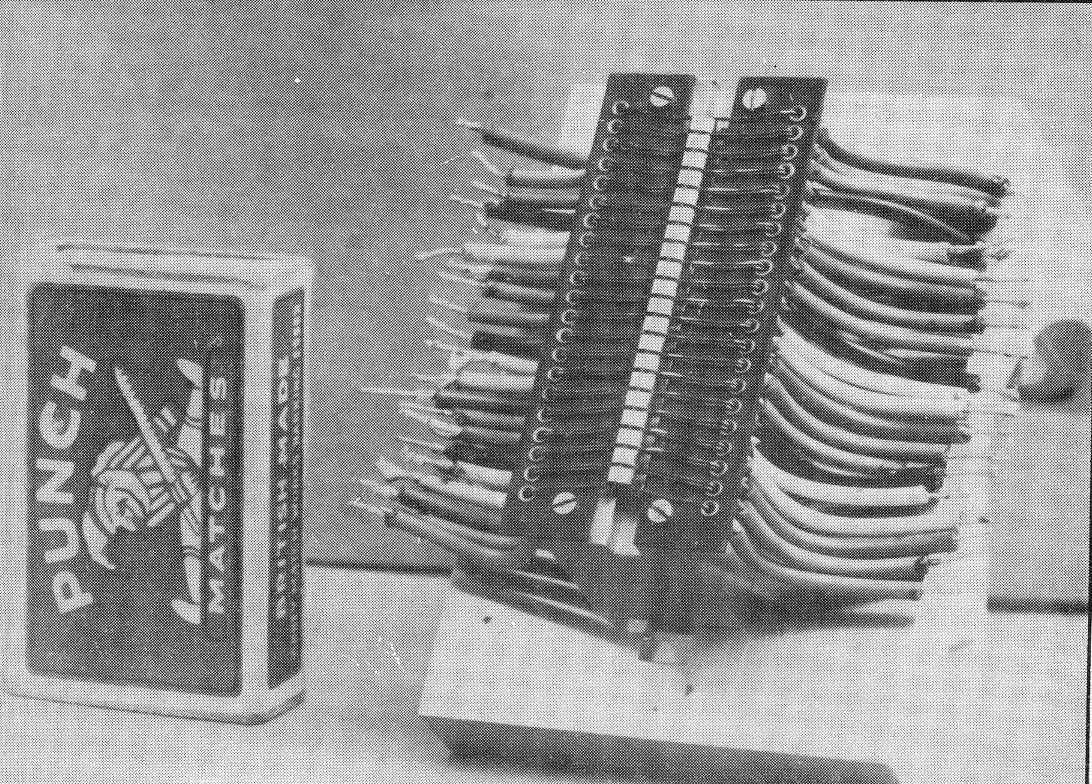
The actual storage system is illustrated in Fig.4. The magnetic material employed is a .001" layer of dull nickel. Separate heads are used for writing and reading, this being necessary due to the delays of digit detection experienced in our method of digital representation which is the phase-modulation method previously described. The heads employed are effectively a single turn of wire enclosed by a .005" thick path of radio-metal which has a gap of .00025" width and of about .1" length. Each of the heads, i.e. writing and reading, are identical and have a separation of about .015". These heads are built at the moment in blocks of 20 which just fills the 2" but we propose in the very near future to extend this to 64 to the 2". An example of the 20 head is shown in photograph 2. The block of heads is bolted to the mounting bracket previously described and by means of the vernier adjustment is approached to between .001" and .002" of the wheel.
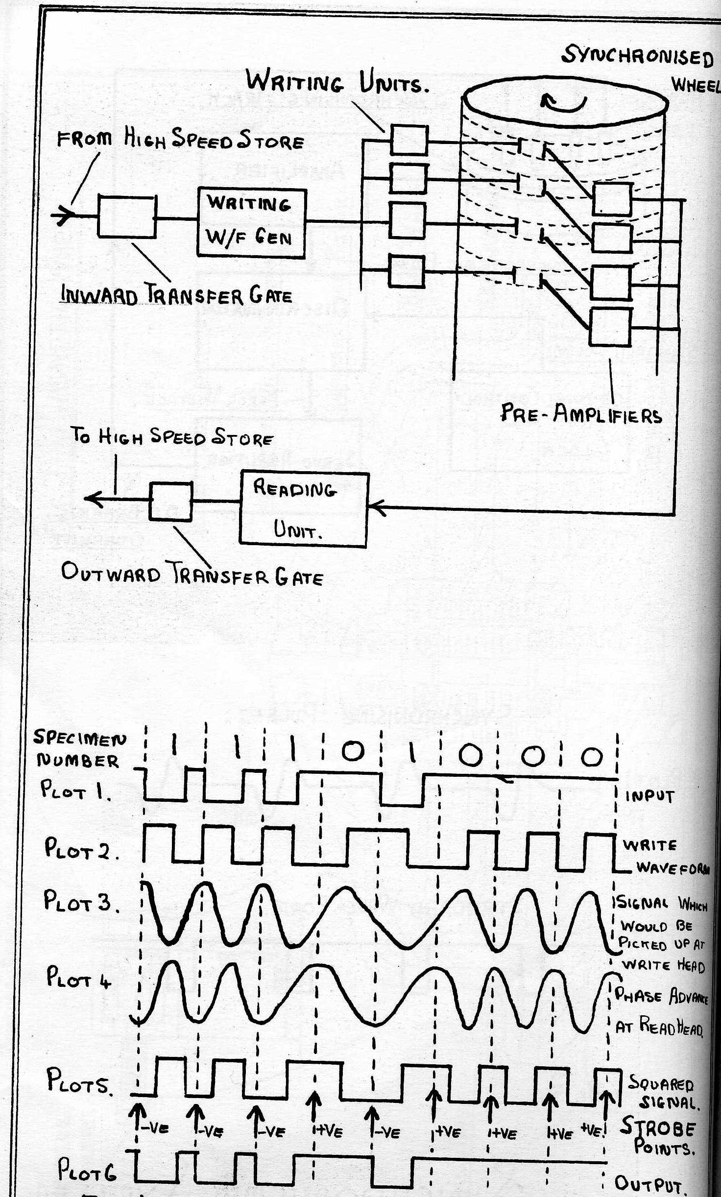
Each track on the wheel is at present loaded completely in one operation, the 2560 digits all being written in one operation. The information from the high-speed store enters the system by an inward transfer gate. The digits in serial form are shown in plot 1 where a 6 m.sec. negative pulse represents a 1 and a zero level represents a 0 this being the standard form of digital representation in the machine. These pulses generate in the next unit which is called the write wave-form generator a voltage waveform of the form shown in plot 2 which is the pattern required for the phase modulation method of representation previously described. This wave-form is now employed to drive a push-pull current amplifier which feeds a current waveform of exactly the same shape and of about 15 amps, amplitude to the selected writing head.. This large current is obtained by the use of two correctly matched pulse transformers, one in the anodes of the push-pull circuit and one directly attached to the writing head. The selection of the writing head is done at the moment by means of a manual switch between the first transformer in the write unit and the head transformer, this system can obviously be made automatic by the use of relays in this position. The alternative method of selection which is represented in Fig.4 requires a separate write unit for each track. Each write unit comprises 3 valves but the selection in this case would be purely electronic and correspondingly faster. Both systems of selection have their advantage, however, and for tracks which are not written on to any large extent relay switching will probably be used. The write unit is activated for one complete revolution and the 2560 digits are written on the periphery each digit being inscribed in its appropriate cell due to the accurate timing of the wheel.
The reading head is displaced by about .015" from the writing head in a direction opposite to that of the direction of rotation of the wheel. This head is therefore effectively 12 m.secs in advance of the writing head as regards timing. Each reading head is connected to a single valve preamplifier which is switched electronically by means of address trees on its suppressor. Therefore when the contents of a particular track are required the appropriate pre-amplifier is opened and the output is fed to a reading unit which is common to the whole bank of pre-amplifiers. The signal is first amplified to the 10 v. level and then squared to give the wave-form shown in plot 5. The level of this square wave is tested by a fine strobe of about .5 m.sec. duration at the beginning of each digit period. The phase advance of the pick-up signal is controlled by the adjustment of the two heads so that this strobe lies in the middle of the square wave and so allows a maximum of tolerance. Thus assuming no phase losses in the reading circuit the waveform which is picked up by the write head would be of the form shown in plot 3, this is 5 m.sec. too late if we require the wave-form shown in plot 5. Therefore we must give the read signal an advance of at least 3 m.sec. to produce a wave-form of the form shown in plot 4. To further compensate for phase losses in the amplifier the actual separation of the heads is about double this. If the strobe finds a negative level then a 1 is indicated and the unit releases a 1 which is a 6 m.sec. negative pulse, and if the strobe finds a positive level then a 0 is indicated and the output level is unchanged. This string of output pulses is then gated by the outward transfer gate.
The drum as described is capable of filling one high-speed store in 30 m.secs. and each digit position on a track has its exact counterpart in one of the 2560 possible storage positions on the storage tube. It is of course possible to transfer, with suitable gating, any one particular digit or group of digits but due to the limitation of access time it is not contemplated to transfer other than whole tracks at a time. When a transfer is required in the course of a computation a special magnetic instruction contained in the instructions present in the high-speed store directs the transfer. This magnetic instruction specifies the address in the high-speed store and the address in the magnetic store between which the transfer is to take place and it also dictates the direction of transfer and any other condition applicable during the transfer. Using such instructions, the high-speed store may be continually reloaded during the course of a computation and this will enable programmes longer than the available high-speed storage capacity to be solved speedily. Using this system we may cut down on the size of the high-speed store as long as the computational time is considerably greater than the time occupied in transfers during the course of the computation. In this application we see that the magnetic wheel, is acting as a subsidiary to the high-speed store and acts as a saving in the size of the high-speed storage which is of necessity more intricate and difficult to maintain. Apart from this picture of a drum with a large number of tracks which are immediately available in the course of a computation it seems practicable to maintain other drums all running in synchronism with the machine for the storage of other permanent data such as tables and previous programmes for which the access time required may be small. This envisages a library of drums any track of which is immediately accessible on demand.
This brief outline will give some indication of the fascinating possibilities of a method of storage which is still comparatively in its infancy.
(1) "First Progress Report on a Multi-Channel Drum Inner Memory for use in Electronic Digital Computing Instruments." by Bigelow, Panagos and others. Electronic Computer Project. Institute for Advanced Study, Princeton, N.J. 1948.
(2) "Selective Alteration of Digital Data in a Magnetic Drum Computer Memory." - Engineering Research Associates, St.Paul, Minn. - Dec. 1947.
(3) "Survey of Magnetic Recording." - Otto Kornei. page 223. "Magnetic and Phosphor Coated Discs." - B.L.Moore, page 130. Vol. XVI. Annals of the Computation Lab. of Harvard University. Harvard University Press, 1948.
(4) "Memory Devices".' - C.B.Sheppard. 21-1 ... 21-28. Vol. I. II. "Magnetic Recording". - Chuan Chu 27-1 ... 27-17. Vol. II. III. Moore School Lectures. University of Pennsylvania, 1947.
(5) "A Magnetic Digital Storage System." - A.D.Booth. Electronic Engineering 2l, 234, July, 1949.
