
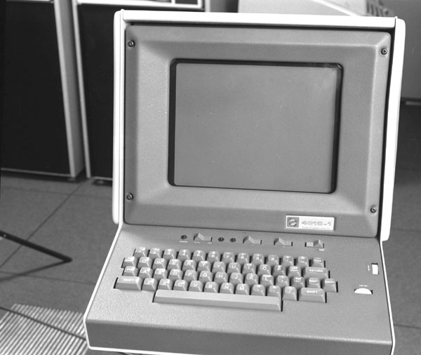
The Tektronix 4010 was available from the early 1970s. It could be used as a VDU, or as a graphics display. The display was a storage type cathode ray tube which means that once the image is drawn it remains on the screen until a complete refresh takes place. This was particularly attractive for the interactive systems of the ICF as the load on the central system was quite low especially if the driver for the display was optimised to keep the graph drawing commands to a minimum. The two thumbwheels on the right could be used to move the cursor. If the screen was hit with a low intensity drawing command, the image did not become stored which was how the cross hairs were moved but it did mean that they were of quite low intensity.
The display had a resolution of 1024 by 768 in graphics mode. It was used in the ICF for simple graphical output (charts and graphs). For any CAD activity, the newer and larger 4014 was much preferred.
The 4010 could be switched into Graph Mode after which subsequent output was interpreted as vector drawing commands until it was switched back into Alpha Mode. The first command always moved the beam and subsequent ones drew vectors. To get a set of unconnected vectors, it was necessary to insert another Enter Graphics Mode control before each pair of points.
D The command consisted of four bytes (5 low bits per byte define the coordinate, the high order tag bits determine the command). Thus the four bytes defined (HiY, LoY, HiX, LoX) and either the beam was moved to that position or a line was drawn from the current position to this position dependent on the state. For example, if the 10 bits defining the Y coordinate was abcdefghij and the 10 bits defining the X were klmnopqrst, the four bytes including the tag bits would be:
01abcde 11fghij 01klmno 10pqrst
The LoX byte caused the vector to be drawn.
The first three bytes were stored in registers in the terminal and did not need to be resent if they were the same as the previous command although the LoY byte had to be sent if the HiX byte had changed. This was the major method of optimising the line usage and speed of the machine.
