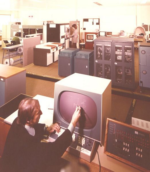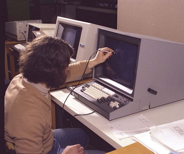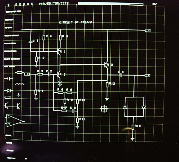


To use a fully interactive display on a multi-user computer, it is necessary that the basic systems tasks needed to be handled in a local processor to the display. Early on, in the ICF, an assessment of potential systems was done by Len Ford. The main contenders were the DEC GT41/VS60, the IMLAC PDS-4, Vector General, Evans & Sutherland and the Ferrant GT7. To encourage the UK industry, it was recommended to the ICF Committee that a Ferranti system should be purchased for assessment and the Department of Trade and Industry agreed to fund it. Unfortunately, Ferranti decided not to sell the system and we opted for the proven IMLAC PDS-4.
IMLAC were formed in 1968 and had initially sold a PDS-1 that became unintentionally famous for its use as a games machine, it was designed as a terminal for the stock exchange! By 1977, they had sold about 700 PDS-4s. The first system was installed at RAL for assessment and software development and two others were installed in universities by the end of 1977. About 15 IMLAC systems were eventually purchased. There was a back-end called DINO that allowed the PDS-4 to talk to GINO-F.


The IMLAC had a conventional CPU that handled the interaction with the remote computer (in our case a Prime 400 initially). It could also obey a display list that was interpreted by the display. When changes were required on the display, the commands to update the display list were sent from the Prime to the IMLAC PDS-4 Processor. The PDS-4 had the following order code:
7-bit Op Code and 11-bit address, N stands for number, *N stands for contents of an address, AC stands for Accumulator and PC stands for Program Counter.
LAW N    004 N  Load AC with N
LWC N    104 N  Load AC with 2's complement of N
JMP N    x10 N  Load PC with N
SAD N    x14 N  If *N ≠ AC, increment PC
DAC N    x20 N  Deposit AC into *N
XAM N    x24 N  Exchange AC and *N
ISZ N    x30 N  Increment and skip at 0
JMS N    x34 N  PC into *N, jump to N+1
DCM N    x40 N  Decrement *N by 1
AND N    x44 N  AND *N into AC
IOR N    x50 N  IOR *N into AC
XOR N    x54 N  XOR *N into AC
LAC N    x60 N  Load *N into VAC
ADD N    x64 N  Add *N to AC
SUB N    x70 N  Subtract *N from AC
SAM N    x74 N  If *N = AC, Increment PC
This gives a flavour of the basic machine order code. It also had a stack on to which values could be pushed and popped from either the Accumulator or Program Counter (useful for subroutine jumps). It also had a set of commands for starting and stopping the operation of the display processor
In Long Vector Mode it was capable of drawing full length vectors. The DVLM command entered long vector mode and could define the vector command as being with the beam off, solid, dashed or dotted.
The end position was defined by two words:
0 100 0Sm mmm mmm mmm M
R HTB CSn nnn nnn nnn N
The two 10-bit values M and N define the longest and shortest coordinates as follows:
In medium vector mode it could define a sequence of line draws one per word once the instruction was initialised.
0 100 100 0RH TB0 0FF
L Smm mmm mCS nnn nnn M and N
The line increments were 0 to 63 positive or negative in the X and Y. The meaning of S, B, H, T and C was as before.
Other commands gave the ability to rotate all the coordinated by a factor of 90°, reflect the coordinates, change the intensity blink the drawing commands.
The short vector mode was only of use for very short lines in terms of X and Y increments.