

R A Barfield and J V Oldfield
1974
Focal Press
ABSTRACT
This chapter describes a program written in FORTRAN designed for the non-programmer to produce geometrical computer-animated films with a three-dimensional effect. The program uses an ASP data structure package and the idea of constraining picture parts with some interaction. It runs on an ICL 4130 with a link to a DEC PDP-7 with a 340 display.
Visual aids are being used to an increasing extent in schools, and recently projectors have been developed based on the cassette principle which allow even the child himself to use movie material. For mathematics and in particular geometry, animation techniques are useful but the material presents difficulties to the animator. Sequences are often monotonous- to produce and yet standards of accuracy are demanding. It is natural to turn to computers fitted with displays for more automatic ways of generating movie film.
Most computer display systems have a package of graphic subroutines by which a user program typically in Fortran may generate a display. It is tedious to use these for animated movies since often frames which differ only slightly involve many calls to the graphic subroutines. Various workers have implemented languages or packages of subroutines specifically for movie-making but these still demand too much attention to detail for the maker of animated sequences on mathematics.
We have developed a program in Fortran which enables the user, without any knowledge of a programming language, to move lines, curves, and other shapes along particular paths in 3-D and fade them on and off without having to bother about the mathematical details, such as perspective.
One of the main features of our program is that the user may constrain picture parts, lines, circle segments etc., to have a particular relationship to one another so that however one part is moved,the others will automatically follow. The constraints on the parts are solved mathematically by the program, and we believe this is a unique method in this particular field.
REQUIREMENTS IMPOSED BY THE MOVIE MAKER
A typical movie is illustrated by the storyboard shown in Fig. 8.1.
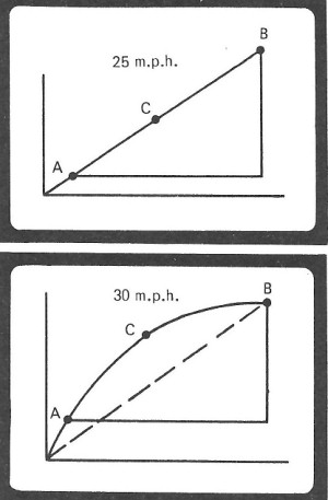
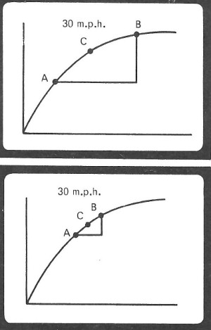
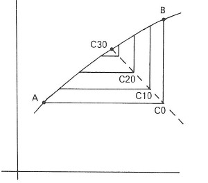
Fig 8.1: Extract from typical storyboard
The axes and curve are to appear for 3 successive frames while the point C is moved from C0 to C30, and the horizontal and vertical projections shrink to zero. The captions X and Y must move and shrink to suit. It should only be necessary to specify picture parts and the sequential operations such as that the line AC must be horizontal with one end point on the curve and the other controlled by an invisible mover which moves at a constant rate in a specified direction. Similarly the captions are related to their projection line segments in both position and size.
Some material involves three-dimensions and the computer is particularly suitable for carrying out the necessary transformations for two-dimensional views. Although the movie maker would like to represent collections of arbitrary surfaces with half tone views, because of technical difficulties we have only chosen to allow objects composed essentially of lines and points. Moreover, the hidden line problem has been ignored. In contrast for some strictly two-dimensional material care must be taken to avoid the illusion of 3-D. One method involves the use of coloured lines and the movie maker can associate colours with picture parts.
Although the distributed material is in the form of 8 mm film loops, the master copies are produced with 16 mm stock for picture quality and ease of manual editing if necessary.
DATA FORMAT
The use of Fortran means that certain restrictions are imposed on the data format, e.q, a symbol input can not be used to control the remainder input on that line, but can be used for the following line end. The input of letters must be in groups of four. Free format input is used because no padding out of numbers with zeros is necessary, and commas are useful terminators of numbers. However a certain amount of padding out with spaces is required, and with this particular compiler the last number input on a line must be followed by a decimal point if the data is to be read in with the same reader as used for the program.
The following is a straightforward example to produce 1000 frames based on the storyboard shown in Fig. 8.1.
It will be seen that the program calculates the latest positions of all the points in each frame in view of the constraints upon those points while the user moves one point only. This example does not demonstrate all the facilities available with the program e.g. macros or circles.
DATA TAPE WITH ANNOTATIONS
(        )
(F0.0.   .F0.0)
(F15.7,   )
(F   .F0.0)
1A4   2A4   3A4   4A4   5A4   6A4   7A4   8A4   9A410A4
110   210   310   410   510   610   710   810   9101010
118   218   318   418   518   618   718   818   918101B
POI   1.                              /Point A defined
  100,100,100.
POI   2.                              /Point B defined
  500,100,100.
POI   3.                              /Point Q defined
  800,100,100.
LIN   1.                              /Line ABQ defined
  1,3,1,1,1500,0,0.
POI   4.                              /Point V defined
  250,850,200.
POI   5.                              |
  100,100,100.                        |   Moves point 5 from V to A
MIL   1.                              |   so drawing line VA. Point 5
  4,1,5,51,100.                       |   may now be used for A
LIN   2.                              |   instead of 1 if desired.
  5,4,1,51,1500,0,0.                  |
POI   6.                              |
  100,100,100.                        |
MIL   2.                              |
  4,2,6,101,150.                      |   Similarly draws VB.
LIN   3.                              |
  6,4,1,101,1500,0,0.                 |
POI   7.                          | /Point S defined
  200,400,200.                    |
CCO   1.                          | /S constrained to lie on VA.
  7,5,4,200,250.                  |
POI   8.                              |
  0,0,0.                              |
CCO   8.                              | Point is moved from Q to S
  8,5,4,250,1500.                     | where it becomes S. Point 7
MIL   3.                              | was used as S for reference
  3,7,8,201,250.                      | in drawing  QS only.
LIN   4.                              |
  3,8,1,201,1500,0,0.                 |
POI   9.                              |
  0,0,0.                              |
CCO   2.                              | Point T defined so that it
  9,4,6,300,1500.                     | lies on VB and QS.
CCO   3.                              |
  9,3,8,300,1500.                     |
POI  10.                              |
  0,0,0.                              |
MIL   4.                              | Draws TA.
  9,1,10,301,350.                     |
LIN   5.                              |
  10,9,1,301,1500,0,0.                |
POI  11.                              |
  0,0.0.                              |
MIL   5.                              |
  8,2. 11,401,450.                    | Similarly draws SB.
LIN   6.                              |
  11,8,1,401,1500,0,0.                |
POI 12.                               |
  1.0,0.0.                            |
CCO  4.                               | Point K defined as lying on
  12,9,1,500,1500.                    | SB and TA.
CCO  5.                               |
  12,8,2,500,1500.                    |
POI 13.                               | Point P defined as lying on
  0,0.0.                              | AB abd VK between
CCO  6.                               | frames 500 and 550 and
  13,12,4,500,550.                    | will be used for reference
CCO  7.                               | only in drawing VP.
  13,1,2,500,550.                     |
POI 14.                               |
  0,0,0.                              |
CCO  9.                               | Point P defined after
  14,12,4,550,1500.                   | frame  550.
CCO 10.                               |
  14,1,2,550,1500.                    |
MIL  6.                               |
  4,13,14,501,550.                    |
LIN  7.                               | Draws VP.
  14,4,1,501,1500,0,0.                |
POI 16.                               |
  500,1000,500.                       |
POI 15.                               | Moves V in a circle centre
  600,1000,800.                       | point 16 to point 15.
MIC  1.                               |
  4,15,16,4,601,690,-1.               |
POI 17.                               |
  100,300,500.                        |
MIL  7.                               |
  4,17,4,691,750.                     | Moves V along one straight
POI 18.                               | line and then along another.
  400,800,300.                        |
MIL  8.                               |
  4,18,4,751,800                      |
POI 19.                               |
  300,700,200.                        |
MIL  9.                               | Moves S along a straight
  8,19,8,801,900.                     | line
FIN  1.                               |
COMPUTER SYSTEM EMPLOYED
Most computer-made films to date have been made on computer film recorders (e.g. SC4020), which are essentially non-interactive. The work described here has been carried out on a system primarily developed for interactive computer graphics illustrated by Fig. 8.2. The movie program, written in Fortran, is executed by the I.C.L. 4130, a medium-scale scientific computer. It uses both graphics (SPINDLE) and data structure (ASP) packages in producing display instructions for the D.E.C. Type 340 display. The PDP-7 is concerned with updating the display, controlling both the link transmissions and the on-line movie camera mounted in front of the slave display, as well as handling interrupts generated by the user with the light-pen and keyboard. The PDP-7 can also store the display files with incremental changes on DECtape, an economic magnetic tape system. These tapes can subsequently be used for frame expansion and contraction editing without the need for the larger computer. A standard executive program in assembly language is used to provide all these functions and the movie program is strictly confined to the larger computer and the ASA Fortran language.
OPERATION OF THE PROGRAM
The major sections and sequence of operation are shown in Fig. 8.2.
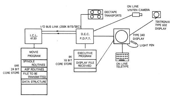
Fig 8.2: System developed for interactive computer graphics
DATA INPUT
A data tape as described under the subject of data format above is read in line by line. Each object is identified by giving its type and number on the first of a group of consecutive lines. The type controls the number of additional lines expected, which provide additional information. Suitable error messages are output e.g. if a point or instance is referenced before it has been defined.
The ASP data structure of elements, ring starts and associators is set up as the data is read in.
CALCULATION OF POINT CO-ORDINATES FOR EACH FRAME
This routine determines which movers are relevant to the particular frame. Any points immediately under the control of a mover are then considered and their co-ordinates determined. For any instance with an attachment point under the control of a mover, it is necessary to change the associated instance matrix.
The routine then finds any relevant constraints for the particular frame and applies them. The method of solution is given later. As with movers, this may involve changing instance matrices. For any given instance matrix so affected, it is necessary to change any other instance matrix with an attachment point forming part of it. This in turn may lead to other changes. Each point or instance affected is tagged so that the convergence may be controlled.
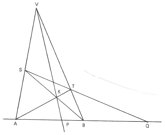
Fig 8.3: A point in three-dimensional space is normally represented in the form (X,Y,Z), the three co-ordinates X,Y, and Z being the distances measured along three mutually perpendicular axes.
Purpose
To construct the harmonic range (AB, PQ) or to obtain the harmonic conjugate of Q with respect to A,B.
Details of the construction
- Choose any three points on a straight line, A, B, Q.
- Choose any point V off the line.
- Join VA and VB.
- Draw any line through Q to cut VB in T, VA in S.
- Join SB, TA intersecting at K.
- Join VK and produce to cut ABQ at P.
Teaching Point
- Having fixed A, B, Q then P is a unique point.
- The construction is a random one and depends only on incidence i.e. lines joining points and lines through points.
Demonstration on Film
Keep A, B and Q fixed but vary VA, VB and QTS, by moving V and line STQ.
SHOWING FRAME ON THE DISPLAY
The display file is arranged in segments and each instance is defined as a segment but for objects not in a macro, each object is defined as a segment.
Two passes of the structure are made for each frame. In the first segments not requiring to be changed (i.e. the points on which they depend are unchanged) and those requiring permanent deletion from the display file are noted, the latter deleted in reverse order, so releasing display file space, before the second pass. In the second pass segments requiring definition are defined using the SPINDLE subroutines having first used a matrix transformation on the X, Y and Z co-ordinates of the points to obtain a perspective view and the required intensity modulation calculation.
The complete display file is sent over the link every 500 frames and updated for each frame in between. The display file or amendments, for each frame are dumped on magnetic tape in the PDP-7 using the filing system, a new file being created every 500 frames. A frame is displayed on the 340 display simultaneously with its dumping onto magnetic tape.
INTERACTION
If there has been an F typed on the PDP-7 teletype keyboard once the display file has been dumped, the frame number is output. The new number typed in is the frame number from which the program is to continue. Unless this is the same as the frame number previously output, the program rounds this off to the multiple of 500 below this, opens a new DECtape file and carries on from the rounded off frame number, having recalculated the frames up to this number.
The user may also inhibit dumping the display files and study individual frames by commands from the PDP-7's Teletype as well as determining and changing the co-ordinates of a particular point.
USE OF ASP DATA STRUCTURES
A data structure is a system set up within the memory of the computer used to represent any structure in the outside world by splitting this into its component parts, collecting together similar components and showing how they are related in a logical manner. In our case, the structure is the picture itself and the components the picture parts. This mathematical model facilitates finding a particular component and adding to or deleting from the structure.
A ring is simply a chain of items each being pointed to by the previous one and pointing to the next one. A.S.P. consists of rings of associators, rings of ringstarts and elements.
The highest level ring in the structure is the ring of associators, each pointing to a macro's element with a lower ring of ringstarts. Each of these are associated with a particular type of object (point, line etc.) and the associators on their rings point to an object's element appearing in the definition of the macro. Another ringstart has a ring of associators each pointing to the element for an instance of the macro.
The upper ring of a line, circle, conic or text element consists of an associator on a macro's ring of lines, circles, conics or text, plus associators to the lower rings of point elements used in its definition. The lower ring of a point element has 3 ringstarts, the associators on one ring pointing to line elements etc., using this point, those on another to constraint elements and those on the third to instance elements using this point as an attachment point. The upper ring of an instance element has an associator on the instance ring of an identity, one pointing to the lower ring of its attachment point and others pointing to the lower rings of other instance elements in whose definition the former appears.
The association of an associator pointing to a point, in a macro is a pointer to the instance in which the point is referenced.
CONCLUSIONS
The first version of this program dealt with two-dimensions only, had fewer types of picture parts and constraints, no macro facilities, no interaction and no proper data structure system. A film was completed entitled Calculus which deals with some elementary ideas of average speeds.
There are many improvements we would like to make to the program and to the system amongst which we list:
- The addition of colour to picture parts for emphasis and variety.
- The production of half-tones to display and shade surfaces in three dimensions.
- An increase in the use of interaction both to add and delete picture parts using the keyboard and light pen to identify particular parts. This would improve the positioning of text on the screen with which much difficulty has been experienced to date.
- The development of a more flexible language to replace the data format.
- The display of abstractions e.q. constraints and movers, and with (3) the alteration of these using the light pen on line.
- A reduction in the size of the program and faster operation.
- An improvement in characters to make them acceptable to animators and an infinitely variable intensity to improve both mixing facilities and perspective effects.
HOMOGENEOUS COORDINATES
A point in three-dimensional space is normally represented in the form (X,Y,Z), the three co-ordinates X, Y, and Z being the distances measured along three mutually perpendicular axes Fig. 8.4. However we can represent the same point in the form (x,y,z,w) where x = X/w etc. known as the homogeneous form; w can be considered as a scaling factor.
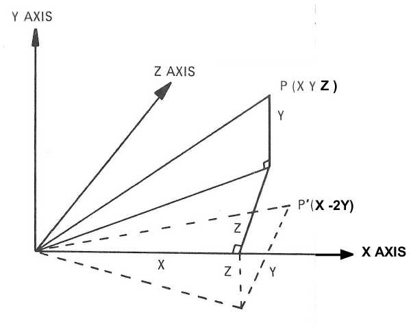
Fig 8.4: A representation of the rotation of any point about any axis and throughany angle.
ROTATION
Rotation of a point represented as (X,Y,Z) about any axis and through any angle is effected by post multiplying by a 3 × 3 matrix. e.g. (X,Y,Z) rotated about the X axis through 90° becomes
(X,Y,Z) | 1  0  0 | = (X,-Z,Y)
        | 0  0  1 |
        | 0 -1  0 |
In homogeneous co-ordinates a 4 × 4 matrix is of course used
(x,y,z,w) | 1  0  0  0 | = (x,-z,y,w)
          | 0  0  1  0 |
          | 0 -1  0  0 |
          | 0  0  0  1 |
TRANSLATION
To shift (X,Y,Z) to (X+e, Y+f, Z+g)
(X,Y,Z,1) | 1  0  0  0 | = (X+e,Y+f,Z+g,1)
          | 0  1  0  0 |
          | 0  0  1  0 |
          | e  f  g  1 |
SCALE CHANGE
To change w to ws
(x,y,z,w) | 1  0  0  0 | = (x,y,z,ws)
          | 0  1  0  0 |
          | 0  0  1  0 |
          | 0  0  0  s |
PROJECTIONS
Orthogonal and perspective projections on to any planes.
e.g.      | 1  0  0  0 | effects an othogonal
          | 0  1  0  0 | projection on to the
          | 0  0  0  0 | plane z=0
          | 0  0  0  1 |
and
          | 1  0  0  0    | effects a perspective projection
          | 0  1  0  0    | on to  the plane z=0 with the
          | 0  0  0  01/H | point (0,0,-H) as  the centre of
          | 0  0  0  1    | perspective. See Fig 8.5
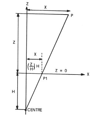
Fig 8.5: A perspective projection on to the plane z=0 with the point (0,0,-H) as the centre of perspective.
MACRO FEATURE
A collection of objects - lines, text, conics and points - may be grouped together as a single entity (a macro) and recalled in different parts of the film by a single call without having to redefine the original objects. These new instances of the object may be in different positions and orientations from the original instance of the macro.
The new instances are represented in the data structure as 4 × 4 matrices and the actual position of a point within an instance is determined by post-multiplying the co-ordinate form of the point in the original macro by this 4 × 4 matrix.
An instance of one macro may be defined as part of another macro. Every instance is attached to a point, which may be a point of an instance, which may be moved or constrained and the instance follows it. An instance of a macro may also be rotated about an axis, and in this case, any instances of other macros defined within the rotated one are similarly rotated.
Unfortunately due to the use of 3-D and the calculation of perspective the program is unable to use the sub-picture facility of the 340 display.
CONSTRAINT SOLUTION
The routine CALC looks at all the points definitions on the rings and solves the constraint on each point if any are defined in that particular frame. If any of the points have changed their co-ordinates because of this process, it is repeated until all points have been fixed.
To solve the constraints on each point, routines are used which give the co-ordinates of a point on a line, sphere or plane nearest to the given point, so that if point 1 is constrained to be collinear with 2 points, 2 and 3 say, and be on a sphere, whose centre is point 4, and on which point 5 lies, 1 is moved alternately to the line on which 2 and 3 lie and to the given sphere until the movement is less than .5 unit in the X,Y and Z directions (see Fig. 8.6). In the case of line cutting a sphere in 2 places the point moves to the nearer and in the case of the line not cutting the sphere at all an error message is output. The latter case is discovered when during the iteration process it returns to a previous position.
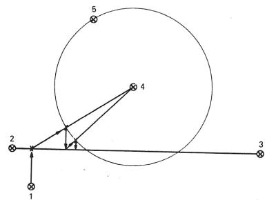
Fig 8.6:
Other constraints are solved similarly:
- Point on plane (defined by 3 other points) by moving to the nearest point on the plane.
- Point 1 a distance b from point 2 in the X/Y/Z direction - simply set the X/Y/Z coordinate of 1 to X/Y/Z of 2 + b.
- Point 1 on circle centre 2, through 3, in the plane of 2,3,4. Move 1 to plane 2,3,4 then to sphere 2,3.
- Point 1 on a plane through 2 and perpendicular to the line 2 - 3. Move 1 to the required line through 2.
- Point 1 on a line through 2 and perpendicular to the plane 2,3,4. Move 1 to the required line through 2.
- Point 1 such that 2 is equidistant from 1 and 3. Move 1 to the sphere defined by 2 and 3 with 2 as the centre.
- Point 1 on the plane tangential to sphere 2,3 at 2, centre 3. Move 1 to the required plane.
- Point on the line tangential to the circle at 2 centre 3, in the plane 2,3,4. Move 1 to the plane 2,3,4 and then to the plane perpendicular to 2 - 3 and through 2.
Assigning a constraint the value 2/3 if it consists of moving the constrained point to a surface/line means that if the total value of constraints on a point at a particular time is less than 5, the point is under-constrained, but whatever constraints are carried out, if it is 5, 6 or 7, the point is correctly constrained and if it is greater than 7 the point is over-constrained, an error message is output and an attempt is made at solution. Even if the point is officially correctly constrained it may happen that, for example, two lines do not meet and the constraints cannot be solved as above.
In the first frame the constraints in each entity are solved but not in later frames so that all instances of an entity are the same basic shape.
  Point:
POI  <identifier><x-coord> <y-coord>,<z-coord>.

  Line:
LIN  <identifier><start point ident><end point ident>,<type>,<frame on>,<frame off>,
     <intensifier ident>,<intensifier ident>.

     <type> is positive for a heavy line, negative for a dotted line

  Intensifier:
INT  <identifier>,<frame on>,<frame off>,<mix>.

     <mix> is positive for fading up and negative for fading off.
           Any object referencing this intensifier has its intensity
           changed0-7 or 7-0 according to MIX from frame on to frame off

  Circle segment
CIR  <identifier> <start pt ident>,<end pt ident>,<centre pt ident>,
      <frame on>,<frame off>,<intens ident>,<intens ident>.

        Drawn clockwise from start point to end point about centre point.

  Conic
CON  <identifier>,<<tangent pt ident>,<start pt ident>,<end pt ident>,<shoulder pt ident>,
      <frame on>,<frame off>,<intens ident>,<intens ident>.

       The conic is drawn from start point to end point through shoulder point. The tangents at start point and end point
       is on lower bisector of start point - end point and at infinity.

  Text
TEXT <identifier>,<angle>,<length of text>,<st pt ident>,<type>,
      <sizer ident>,<sizer ident>,<frame on>,<frame off>,<intens ident>,
      <intens ident>,<text specification>.

       angle is in degrees and length of text is the number of characters.
       type refers to the type of text required and whether upper or lower
       case. There are 3 font types available.
       TYPE= 1 or 2 gives upper or lower case of first font
       TYPE= 3 or 4 gives upper or lower case of second font
       TYPE= 5 or 6 gives upper or lower case of third font
       Text specification must be padded up to the next multiple of 4 characters with spaces

  Size
SIZ   <identifier>,<start size>,<finish size>,frame on>,<frame off>.

       The text in whose definition this identifier appears is sized
        linearly from from start size to finish size between the frames given

  Macro
SUB   <identifier>,<start pt ident>,<frame on>,<frame off>,<intens ident,< <intens ident>.

       This also serves as the definition of this macro's first instance
       with the above starting point. The first point definition following
       SUB is that macro's attachment point i.e. the point which is made
       to coincide with an instance's starting point.

  Terminate a Macro
FIN   <identifier>.

  Macro Instance
INS   <macro identifier>,<start pt indent>,<frame on>,<frame off>,
      <intens  ident>,<intens ident>.

  A mover to rotate an instance
MIR   <ident>,<st pt ident>,end pt ident>,<angle>,<ins  ident>,<frame on>,<frame off>.

       INS IDENT is 1000m + n where the user wishes to rotate the nth
       instance of macro m through angle about the line from st pt ident to end pt ident

  To move a point along a line
MIL   <ident>,<st pt ident>,<end pt ident>,<pt moved>,<frame on>,<frame off>,<direction>.

  To constrain a point  to be on a circle
CCI   <ident>,<constrained pt ident>,<pt on circle ident>,<centre ident>,
      <pt ident to give plane of circle>,<frame on>,<frame off>.

  To constrain a point  to be on a line
CCO   <ident>,<con pt ident>,<pt on line>,<pt on line>,
      <frame on>,<frame off>.

  To constrain a point  on a sphere
CSP   <ident>,<con pt ident>,<pt on sphere ident>,<centre ident>,
      <frame on>,<frame off>.

  To constrain a point so that point 1 is equidistant from it and point 2
CEQ   <ident>,<con pt ident>,<1 ident>,<2 ident>,<frame on>,<frame off>.


  To constrain a point to be on a tangent at point 1 to a circle centre point 2
  and in whose plane lies point 3
CTA   <ident>,<con pt ident>,<1 ident>,<2 ident>,<3 ident>,<frame on>,<frame off>.

  To constrain a point to be in a plane tangential to a sphere centre point 2 at point 1
  and in whose plane lies point 3
CTS   <ident>,<con pt ident>,<1 ident>,<2 ident>,<frame on>,<frame off>.

  To constrain a point so that its X/Y/Z coordinate differs from point 1 by separation

CXX   <ident>,<con pt ident>,<1 ident>,<2 ident>,<frame on>,<frame off>.
CYY
CZZ

  To constrain a point to be in a plane through point 1 perpendicular to a line on which
  points 1 and 2 lie
CPE   <ident>,<con pt ident>,<1 ident>,<2 ident>,<frame on>,<frame off>.


  To constrain a point to lie on a line through point 1 perpendicular to the
  plane containing points 1 and 2 and 3
CPP   <ident>,<con pt ident>,<1 ident>,<2 ident>,<frame on>,<frame off>.
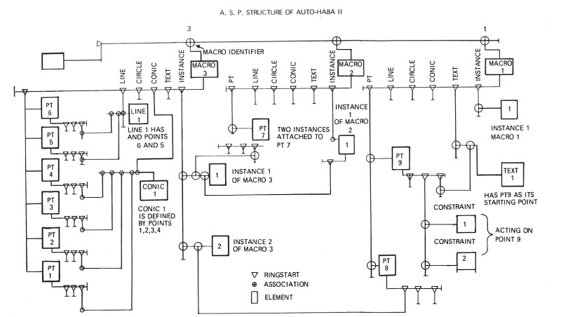
Fig 8.7: A.S.P. Structure of Auto Halab II.