

Kenneth C Knowlton and W H Huggins
1974
Focal Press
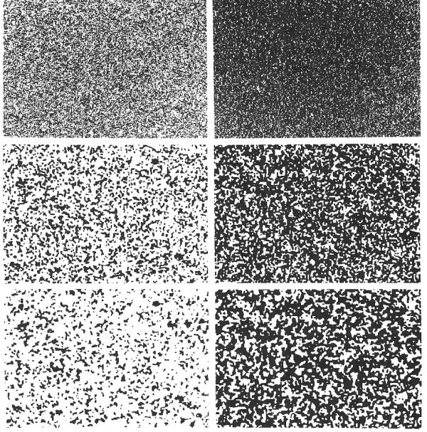
Fig 7.1: Aggregation (agitated crystallization)
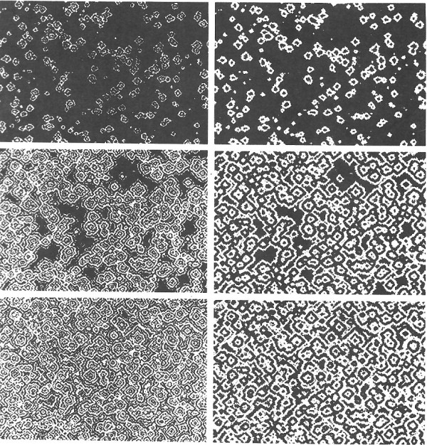
Fig 7.2: Simulation of expanding fringe visual phosphenes
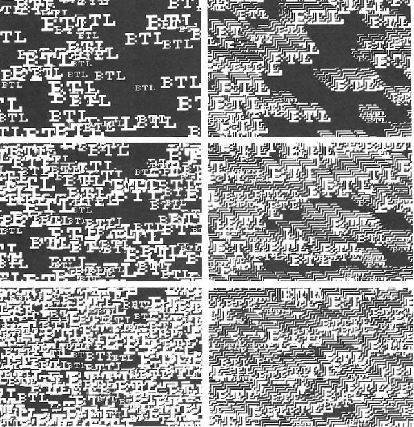
Fig 7.3: Designs from an explicit pattern
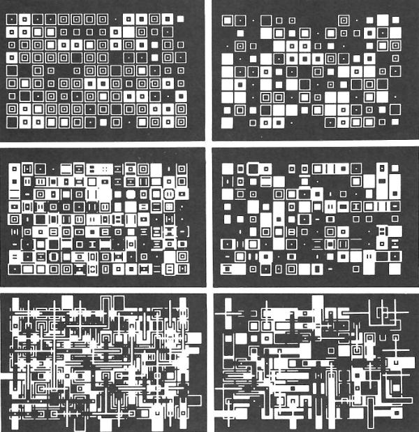
Fig 7.4: Probabalistic squares and rectangles
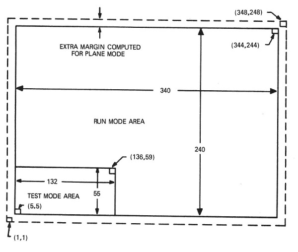
Fig 7.5: The programmer imagines significant areas for different modes of operation - run mode and test mode areas
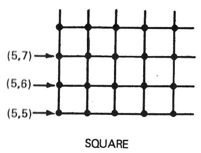
Fig 7.6: Choice of mode: a square arrangement of units
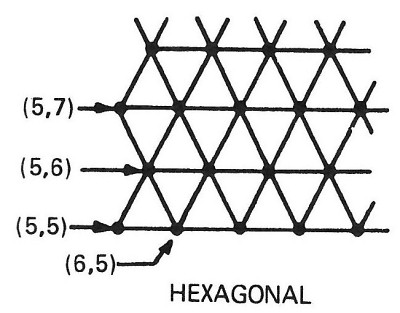
Fig 7.7: Choice of mode: hexagonal arrangement of units
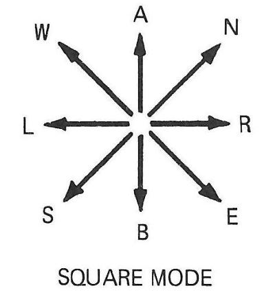
Fig 7.8: Directions specified by letters: square mode
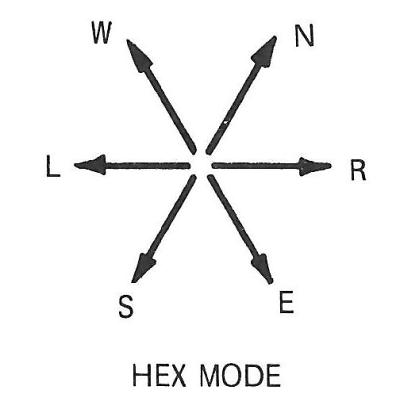
Fig 7.9: Directions specified by letters: hexagonal mode
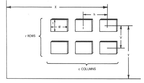
Fig 7.10: Transliterations applied inside regularly arranged boxes
OVERALL LANGUAGE STUDY
The computer is becoming more widely recognized as a useful tool for the production of a variety of animated movies. It can be applied in physics, chemistry, plane geometry, and many other technical areas, each of which, however, requires somewhat different techniques and facilities. For some purposes, black and white pictures are sufficient. For others, colour is required. Some users need a continuous grey-scale, others a discrete grey scale, while others can get along with line drawings, provided that lines are available in a continuous number of intensities. Some users may find a discrete set of line densities or widths sufficient, but in other cases only black and white is needed.
Some computer-animators can manage with image resolutions of 200 by 200, whereas others may need resolutions of 1,000 by 1,000, or even higher. And, whereas in three-dimensional displays, some may manage with wire frame models, others can use approximate treatment of three-dimensional solid models. For still other purposes, exact treatment of the hidden line problem is required.
All of these considerations indicate that a wide variety of languages for computer animation could exist, and without further planning such a variety will inevitably develop, unless a great deal of care, study and planning go into making either an overall complete language for computer animation or a consistent set of intercommunicating modules, with well-defined and rigorously described interfaces between them.
It is important therefore that such an overall study of this problem should be made at this stage, that interfaces should be defined, and that the inner structure of the individual modules should be outlined as far as possible or feasible at the present time. If such a study is made, the main advantages to be enjoyed are these: that different movie making groups will be able to share modules, that they will be able to update their systems more easily, and that a standardization of the pictorial output will be more easily achieved. Thus, the rate of progress would be increased, costs reduced, and the quality of the output would in general, be improved. On the other hand, if no overall plan is developed, the result will be a hodgepodge of many programs or subroutines, written in different languages and in vastly different ways, but with very little generality or possibility of wide application.
MOVIE LANGUAGES AND OTHER GRAPHICAL I/O
Computer animation may be considered as phase or subsection of computer graphics. However, there are many respects in which movie making endeavours have a quality of their own which distinguishes them markedly from areas generally thought of as computer-graphics and time-sharing applications of computers. The following are listed as some of the important distinctions between movie making and real-time graphical applications of computers.
Efficiency
There are two reasons why efficiency of computation is more important in movie making than it is in general for other graphical output from computers. First, in movie making one wants to make thousands or tens of thousands of pictures, rather than a few or a few dozen. Secondly, it is probably more likely that the movie maker is interested in shades of grey, and in realism - in particular three-dimensional effects - which means that a great deal more computation may be required per picture.
Motion
A common way of talking about things which are to appear in movies, is to describe them in terms of their motion and the laws of interaction among these objects. This may not particularly influence the basic computational techniques involved, but it does influence significantly the mnemonics which are used in the programming language.
Camera
In film-making in general, it is customary to think and plan in terms of camera position and motion, that is to say, in terms such as zoom in, zoom out, tilt, rotate, pan, etc. Thus we need another whole category of commands peculiar to movie making.
Language of conditional events
Much more than in other graphical input/output the language for making movies will most preferably be designed in terms of descriptions of conditional events. It will contain such words as whenever, if, when, etc. For example, when such words apply to the camera motion, one would want to be able to say such things as: try to maintain the camera position such that objects A, B, and C never come closer than 5° of visual angle from the margin of the picture, but do not exceed transverse or angular camera accelerations of more than such-and-such an amount.
Visual and aesthetic effects
In computer animation it is the visual and aesthetic effects which are the goal, rather than the conveyance of a precise quantity of information. This means that check-out will be more in terms of aesthetic errors than logical errors in the program. Movie making is actually a form of computer art, and is certainly not a routine matter, at least until the first film of a series is done - at which point the symbols, conventions, and techniques have been established for the series.
Sound
The synchronization of a sound track, however it is made, is another problem peculiar to movie making, and not particularly associated with other graphical or real-time computing.
Optical post-processing
It will undoubtedly be true for a long time that many processes normally used in movie laboratories will remain a part of movie making for computer-produced movies. Processes which probably will be done optically are dissolves, fades, pans, wipes, and duplication of frames. The reason is that, in effect, the optical printer is a large analog device which instantly computes all picture elements simultaneously. Thus, the output of a computer movie making system must be matched to more-or-less standard film-processing equipment.
Modes of operation
In movie making, because of the requirements outlined above under the headings Efficiency and Aesthetic Effects, it will probably be desirable that movie making be done in many possible modes. Thus, even if the desired final result is to be a three-dimensional picture of solid objects, the intermediate or check-out runs may be done in a wire-frame mode. If the final picture is to be done on a 2,048 by 2,048 raster, the checkout runs may profitably be done on a 512 by 512 grid or something even coarser. Also if the final result is to be a movie in three colours, it may nevertheless be possible to superimpose all three primary colours simply as black and white for checkout runs. In fact, the producer may not even know the required resolution or required amount of computation for a particular film until he has seen the approximations which gradually approach the desired aesthetic effect.
SUMMARY
There are a large number of educational and research activities which could use computer-animated movies in a creative and productive way - movies which, without the computer, would be too intricate, time-consuming and expensive to draw and film. But if each potential animator attempts to write his own programs and movie systems from scratch, his accomplishments will be of little use to anyone else and no one movie maker will advance very far.
The present proposal, instead, recommends that computer movie making be examined now and as a whole, noting and studying such topics as are outlined above, in order to arrive at an agreeable set of standards for communication between machines, between subroutines, and between animators.
Another primary goal of the overall study, besides defining interfaces, and describing somewhat the inner structure of modules which meet at these interfaces, would be the estimation of costs of various kinds of computation. As should be obvious from the above, many languages, in effect, can be built by assembling different numbers of different patterns of modules - that is, different groups of subroutines and/or methods of computation from the total array of possibilities presented. Perhaps the most important questions that we can ask about individual modules or collections of them are the following: What will be the cost in terms of money, time, effort, and equipment, to build and check out these various modules, and what will be the cost, again in terms of computational time and programming effort, of producing computer animated movies in different modes of operation? These questions can not be answered trivially to the effect that everything will be possible and feasible, for even though computer operations are speeded up by a significant factor every five years or so, it would take factors of thousands to make certain kinds of movies feasible: those which require very high resolutions in colour and with continuous shadings, with a great deal of computation for each point in three-dimensional space and elaborate rules for establishing visibility or non-visibility of points in this space when projected back to the picture plane.
If such a study is to be effective, it must explore all, or nearly all, of the ideas, needs, languages and superstitions of the potential customers. But a variety of disciplines and interests are involved - it is not easy to communicate among this group. There are no common memberships, registrations or journals either to identify or to serve as communication media. It appears that the first effort on a national scale to bring workers in the field together was a September 1965 conference sponsored by the National Committee on Electrical Engineering Films. It was clear at that time that inter-disciplinary channels of communication left something to be desired. The communication problem will remain unless resolved by an unusual amount of understanding, patience and co-operation among the multiplicity of education and research workers who are, or will be, engaged in some form of computer animation.
THE EXPLOR SYSTEM
EXPLOR is a system for computer generation of still or moving images from explicitly defined patterns, local operations, and randomness. Output images are rectangular arrays (240 x 340 units) of black, white, and twinkling dots; internally, information for each position is encoded as an alphanumeric character.
Scientific and artistic applications include the production of stimuli for visual experiments, the depiction of visual phosphenes such as moving checkerboards and stripes, and picture processing. The system may also be used to simulate a variety of two-dimensional processes and mechanisms, such as crystal growth and etching, neural (e.g. retinal) nets, random walk, diffusion, and repeated arrays of logic modules.
The EXPLOR system is useful for the production of still and moving pictures for a variety of research, educational and artistic purposes, such as the simulation of two-dimensional processes and the generation of displays for psychophysical experiments on human vision.
Each of the images generated is a two-dimensional array of white and black dots like those in Figs. 7.1-7.4, to be described later. Within the computer, information for each position is stored as a digit 0-9, or a letter A,B-Z; the programmer specifies which of these characters are to be output as black and which as white dots, and which are to twinkle, i.e. be chosen at random frame by frame, to be black or white (in other words a fifty-fifty chance).
The programmer imagines significant areas for different modes of operation as shown below. The normal run mode area is 340 units wide by 240 high; in the test mode, only the indicated 132 × 55 area is computed internally, and it is output by printer, not via microfilm (Fig. 7.5).
Another pair of modes, wrap vs plane, specifies whether the surface is considered to be a torus with opposite edges connected, or whether it is a part of a larger plane, in which case an extra four units of margin are computed, preserved and updated but never output. A final choice of modes is between square and hexagonal arrangements of units (Figs. 7.6 and 7.7).
Computation and output are similar for square and hexagonal modes except that in film output for hexagonal mode, even-numbered lines are shifted right by half the dot spacing, and a different interpretation is given to the directions of nearest neighbours. Directions are specified by the letters A, B, R, L, N, E, S, W which may be thought of as meaning above, below, right, left, north, east, south, and west, as shown in Figs. 7.8 and 7.9.
INSTRUCTIONS OF THE LANGUAGE
EXPLOR is a macro language. A summary of instruction names and their purposes are given in Table 1; each of these and its parameters will be described in detail after a few general considerations that apply to most instructions.
| Name | Purpose |
|---|---|
| Picture Output | |
| MODE | established mode as hex or square, run or test, wrap or plane |
| WBT | specify character subsets as white, black and twinkling |
| CAMERA | output the array |
| Changing the internal array | |
| XL | transliteration (table look-up and replacement) |
| AXL | adjacency-conditioned transliteration |
| PXL | specific-pair transliteration |
| BXL | boxed-array transliteration |
| BAXL | boxed-array adjacency-conditioned transliteration |
| BPXL | boxed-array specific pair transliteration |
| Defining patterns | |
| SVP | save a pattern from the internal array |
| PAT | explicitly define a pattern by octal numbers (at compile time) |
| Flow of control | |
| DO | do a subroutine and return |
| GOTO | pass control to named location |
| IF | goto conditional on values of specified parameters |
| Instruction modification | |
| CHV | change the value of named parameter |
| CHP | change pattern named in an instruction |
| XLI | transliterate the specified part of an instruction |
Table 1: Preview of EXPLOR instructions
Instructions have the form:
name opcode(n,p) list-of-arguments goto
where name and goto are optional: a name is required only if control passes to this instruction from any other than the one above it, or if this instruction is to be modified by another instruction; if and when the operation is performed, a goto, if present, causes control to pass to the named instruction, otherwise it goes to the line below.
The periodic and probabilistic indicator (n,p) determines whether the operation and goto will be effective when control reaches this point: every nth time through this point, the system tries to perform the operation, succeeding with probability 1/p (p is an integer); otherwise the operation is not performed and control goes to the next line, whether or not a goto is present. Alternatively, if an X precedes the n and/or the p, then the system tries all times except every nth time, and/or succeeds on all but 1/p of the trials. Examples and their meanings are here given:
- (1, 1)
- always do this operation when control gets here
- (1, 16)
- do this one with probability 1/16
- (4, 1)
- do this one every fourth time
- (8, 2)
- every eighth time through, flip a coin to decide
- (X, 50, 1)
- except for the 50th, 100th, etc. times, do it
- (1, X, 9)
- do it with probability (1.1/9)
- (X, 2, X, 50)
- almost always (p = 1.1/50), do it on the beat
A transliteration, noted as (xlit) in many descriptions of instructions below, is a scheme for replacing some or all of the 36 characters by other ones. It may be specified in one of four ways:
First, a complete sequence of 36 characters specifies, in order, the characters into which 0,1-9, A,B-Z are to be translated. Thus (1234567890BCDEFGHIJKLMNOPORSTUVWXYZA) says that each digit and letter go into the next higher one, with 9 changing to 0 and Z to A. Secondly, if the sequence is truncated, it is assumed that characters whose positions do not appear, remain unchanged. Thus (ABCD) says 0 goes to A, 1 to B, 2 to C and 3 to D, everything else remaining as it was. Third, if the sequence ends in ' .. .', it is assumed that the last character mentioned fills the remaining positions. Thus (012ABC ... ) means the same as (012ABCCCCC CCCCCCCCCCCCCCCCCCCCCCCCCC) and the designation (0 ... ) means that everything becomes zeros. Finally, only specific transitions (at least two) may be specified, separated by commas. Thus (AB,CX,DE) says that A's become B's, C's become X's and D's become E's. If only one such transition is wanted, then a dummy, e.g. change C's to C's, must be added to distinguish this format from the second mentioned: (AB,CC).
Picture-output instructions
- MODE (n,p) (list) goto
- [e.g. MODE (1,1)(WRP,RUN)] establishes the modes of operation by a list of up to three
indicators from the following set:
- WRP or PLN
- to specify wrap-around (toroidal) continuity or plane-mode
- TST or RUN
- to specify test mode (132 × 55, printed output) or run mode (340 × 240), film output
- SQR or HEX
- square or hexagonal arrangement of neighbours
- WBT (n,p) (whites,blacks,twinkles) goto
- [e.g. WBT (1,1) (01234,56789,ABCXYZ)] specifies which characters are output as white, which as black and which ones twinkle (i.e. are independently chosen spot-by-spot, frame-by-frame, to be black or white with 50/50 probability). In the example, 0 to 4 are white, 5 to 9 black and letters A, B, C, X, Y, and Z twinkle; other letters retain their previous significance. Printed output - i.e. from TST mode - is unaffected by WBT; here zeros come out as blanks and all other characters appear as themselves.
- CAMERA (n,p) frames, goto
- [e.g. CAMERA (4,1)2 ] causes the indicated number of output frames of film to be produced if the mode is RUN; if TST, a single page of printout occurs for every seventh frame of specified output.
Instructions for changing the array
- XL (n,p) (list)q(xlit) goto
- [e.g. XL (2,1)3(56,78)] probabilistically subjects all characters of the array to the specified transliteration. In the example, every other time control reaches this point, the instruction is effective - at which time about one-third of the 5's are changed to 6's and about one-third of the 7's are changed to 8's, other characters remaining as they were.
- AXL (n,p) nums,dirs,chst,q(xlit) goto
- [e.g. AXL (1,1)234,RNESW,ABCD,5(XXXX)] is a similar probabilistic transliteration but it applies only to those characters made eligible by adjacent characters: if certain numbers of neighbours in specified directions are among the given character set, then, with probability 1/q the transliteration is applied. In the example, if exactly 2 or 3 or 4 of the neighbours to the right, north, east, south or west are A's or B's or C's or D's, then about one-fifth of the digits 0-9 thus situated are changed to X's.
- PXL (n,p) nums,dir,q(tpls) goto
- [e.g. PXL (1,1)R,1(12A,13B,24C,23X,14Y,348)] transliterates one member of specific pairs. For this operation, the array must contain only digits 0 to 7. In the example, the direction relation is right of and it says that 1's with 2's right of them become A's, 1's with 3's right of them become B's, 2's with 4's right of them become C's, etc.
All three of the foregoing transliterations may be applied (Fig. 10) inside regularly arrayed boxes specified by:
- x,y co-ordinates of centre of top right box
- w,t how wide and tall each box is
- h,v centre-to-centre horizontal and vertical spacing
- c,r umber of columns and rows of boxes
An additional parameter, pat is either the name of an explicit pattern prescribing exactly which boxes of such an array should in fact be treated, or if an integer, it is the reciprocal of the box-by-box probability of treating the box. If w > h and/or if t > v, boxes overlap; overlapped areas are multiply-transliterated. Parts of boxes or entire boxes wrap around if the mode is WRP, otherwise those parts or entire boxes falling outside the frame are ignored. The three instructions have B prefixed to the op code, thus:
BXL  (n,p) pat(x,y,w,t,h,v,c,r)                 q(xlit)goto
BAXL (n,p) pat(x,y,w,t,h,v,c,r) nums,d irs.chst,q(xlit)goto
BPXL (n,p) pat(x,y,w,t,h,v,c,r)             dir,q(tpls)goto
Instructions for defining patterns
Explicit patterns, specifying a subset of boxes of a rectangular array, are defined by 12-digit octal numbers (one digit represents three boxes, a one-bit meaning treat the box). All patterns thus defined are multiples of 35 in width, leading zeros being optional. If the number of columns is more than 36, then two or more of the 12-digit numbers are taken to specify the top row of the pattern, the next group of numbers defines the next row, etc. Thus the pattern named TABLE, which may be taken as a side view of a long 85 × 4 table, is coded remotely (not in line) as follows:
TABLE PAT 37777,777777777777,777777777776
      PAT 00000,200000000000,000000200000
      PAT 00000,200000000000,000000200000
      PAT 00000,200000000000,000000200000
A pattern may be picked up from the array and saved by the same pattern operation which gives the pattern a name and specifies x and y location of the square at the top right corner of the area:
SVP (n,p)name,x,y,width,height,goto
A pattern thus defined from the internal picture is the indicated height and a multiple of 36 wide (wide enough to accommodate the specified width). The pickup routine does not wrap around in picking up characters from the array. Characters picked up are translated according to the current WBT setting, white ones turning into one bits, black ones into zeros and twinkling ones are randomized and preserved as unchanging one or zero bits.
Instructions for flow of control
- GOTO (n,p) goto
- when operative, according to (n.p) simply causes control to pass to the indicated goto. Another transfer of control is conditional upon whether the first parameter is greater than, equal to, or less than the second.
- IF (n,p) (param1,pred,param2)goto pred = GT,EQ,LT
- [e.g. IF (3,2)(SIZE,GT,16)LOC7] In the example, if according to (3,2) the test is operative and if the current value of the variable SIZE is greater than 16, then control goes to the instruction named LOC7. Gotos, clearly, are mandatory for GOTO) and IF statements.
- DO (n,p) subname,goto
- causes the current instruction location to be stacked on a pushdown list and control to go to the subroutine whose first instruction has the indicated name. A subroutine normally terminates logically with the special goto DONE, which causes a pop from the pushdown to direct control so as to continue from beyond the call (to the goto of this instruction if there is one, otherwise to the next line).
Instructions for instruction modification
Many instructions may be operated upon directly (the system is largely interpretive) or indirectly by changing values of parameters referenced. Table 2 contains a resume of all instructions; parameters that are character strings may be changed directly by XLI instructions below, or pattern names changeable by CHP; and named variables which may be changed in value by CHV.
- CHV (n,p)param,change,val1,val2,goto
- [change= SET,ADD,SUB,MPY, DIV]
- [e.g. CHV (1,l)LNGTH,ADD,5,15] sets the parameter to, or adds to it, or subtracts from it, or multiplies it by, or divides it by a value randomly chosen between val1 , and val2, inclusive. In the example, the parameter LNGTH has added to it a number from 5 to 15. If no random selection is wanted, then only the desired number or parameter name need be given as val1, except that if there is a goto, then val2 must also appear (in this case redundantly) in order to preserve the appropriate parameter position for the goto. All parameters have value = 1 until changed by CHV. If a zero value occupies a probability position, p or q, it is taken to be 1.
- CHP (n,p)inst,newpat,goto
- [e.g. CHP (1,1)LINE9,PAT7] causes a change in the named pattern of a BXL, BAXL or BPXL instruction.
- XLI (n,p)name,part,q(xlit)goto
- [e.g. XLI (1,1)LINE5,DIRS,1(NR,RE,EB,BS,SL,LW,WA,AN)]
literally transliterates characters of a part of many kinds of instructions, according to the part specified:
- NUMS
- the numbers of AXL or BAXL
- DIRS,DIR
- he direction(s) of AXL, BAXL, PXL, or BPXL
- CHST
- the character set of AXL or BAXL
- XLIT
- the transliteration of XL, AXL, BXL, or BAXL
- WBTS
- the character strings of a WBT instruction
- TBLS
- the triples of PXL or BXPL
- In the example, the instruction named LINE5 has its named directions changed, each to the next, most clockwise direction.
| Name | Purpose |
|---|---|
| Picture Output | |
| MODE | (n,p) (list)goto [WRP vs PLN, RUN vs TST, SOR vs HEX] |
| WBT | (n,p) (whites,blacks,twinkles) goto |
| CAMERA | (n,p)frames,goto |
| Changing the array | |
| XL | (n,p)q(xlit)goto |
| AXL | nums,dires,chst,q(xlit)goto |
| PXL | (n,p)dir,q(tpls)goto |
| BXL | (n,p)pat(x,y,w,t,h ,v,c,r)q(xlit)goto |
| BAXL | (n,p)pat (x,y,w,t,h,v,c,r)nums, dirs,chst,q(xlit)goto |
| BPXL | (n,p)pat(x,y,w,t,h,v,c,r)dir,q(tpls)goto |
| Defining patterns | |
| SVP | (n,p) name,x,y,width,height,goto |
| PAT | list-of-octal-numbers |
| Flow of control | |
| DO | (n,p)sub,goto |
| GOTO | (n,p)goto |
| TEST | (n,p)param1,pred,param2)goto |
| Instruction modification | |
| CHV | (n,p)param,change,val1,val2,goto [change= SET,ADD,SUB,MPY,DIV] |
| CHP | (n,p)inst,newpat,goto [for BXL,BAXL or PXL] |
| XLI | (n,p)name,part,q(xlit)goto [part= NUMS,DIR(S),CHST,XLIT,WBTS,TPLS] |
Table 2: Summary of EXPLOR instructions
In considering transliteration of instructions by XLI, all character strings may be considered to be stored literally as originally written until changed later; the only characters accessible to change are the digits and letters originally or subsequently appearing. Therefore, some foresight is often necessary if XLI is to be used, for example in providing dummy directions such as X,Y and Z which are ineffective until these characters are transliterated into meaningful directions.
EXAMPLES
The flexibility of the language will be demonstrated, and some of its uses illustrated, by eight examples of programs and their pictorial results. These appear together in sets in Figs. 7.14. The program presented in each case is assumed to be preceded by the initialization
MODE    (1,1) (RUN,WRP,SOR)
WBT     (1,1) (ABCD,0123,WXYZ)
XL      (1,1)1(0...)
which, unless explicitly countermanded by other instructions listed, establishes the ground rules for mode and output, and clears the entire surface to black. Each listed program is assumed to be followed simply by a command to output one frame:
CAMERA (1,1)1
In each case, there is one variable with two alternative values: the upper one causes the left-hand set of outputs, the lower the right-hand set. Another variable shows three alternatives which yield the top, middle and bottom pictures, respectively. In all but the last example, the latter set indicate the interruption of an iterative process after different numbers of iterations.
The first example (Fig. 7.1) is related to crystallization, etching, annealing, and nucleation on a substrate (i.e. simultaneous environment-dependent sublimation and crystallization). The computation starts with either 1/2 or 1/3 white spots (A's) on a black background (O's). The program then agitates by turning black (A's to 2's) one-sixth of the white spots above, below, right of or left of black ones, and then turns white (C's) one-sixth of the black spots next to white ones. (Next for computational purposes, all blacks are recoded as O's and whites as A's). Then the program coalesces by turning white the black spots with predominantly white neighbourhoods (i.e., where 3 or 4 of the 4 orthogonally adjacent spots are white), and by likewise turning to black the white spots in predominantly black neighbourhoods. The process iterates, performing the coalescing operation twice after each agitation.
Other potential uses of EXPLOR are the generation of highly detailed patterns for experiments on vision, and simulation of some of the visual phosphenes, such as squirming checkerboards or fringe patterns, which a person sees when he closes his eyes and presses upon them. Figure 7.2 shows a program for generating expanding fringes from randomly placed nuclei (Y's). The area around a nucleus expands at each step to include all of, or half of, or one-third of the adjacent spots, this probability being chosen at random for each iteration. Each spot progresses backward through the alphabet as it ages, according to the transliteration (00123456789ABCDEFGHIJKLMNOPQRSTUVWXY). Spots represented by N, and older ones, are eligible, with 1 /3000 probability, to become new nuclei for expanding fringes. The left-hand and right-hand outputs show fringes which are three and six iterations thick, respectively.
Fig. 7.3 illustrates the production of designs based on an explicitly defined pattern, in this case the letters BTL. Each time the pattern is laid down, an X-Y location is chosen at random, also a size from 2 to 5. The pattern is first written in O's, then displaced downward and to the right and written in A's. In the left-hand outputs only one black-white pair is written each time; in the right hand set, four successively displaced black-white pairs are overlaid each time.
The last example, Fig. 7.4, is another demonstration of artistic effects, generated here simply as a probabilistic collection of squares and rectangles. The forms are drawn in five successively smaller sizes, alternating between black and white.
TECHNICAL DETAILS
The prototype version of EXPLOR was implemented, for historical reasons, in BE-FAP on an IBM 360/50 emulating an IBM 7094 (with hardware-implemented convert instructions); it occupies 420008 locations, which includes the internal picture storage. The output device is a Stromberg Datagraphics 4060, using a 4020 simulator modified in the following ways: right and left margins were extended giving an effective raster of 1024 × 1366; the period is output as the largest plotting dot, and character spacing in typewriter mode is changed to four 4020 units.
Additional facilities, and also restrictions, implied by these circumstances are discussed below.
Software-imposed restrictions
All of the conventions of Bell Labs macro FAP apply to instruction names and gotos, blanks, op code and argument positions, continuations on next card, comments, and macro-extension of the language. Variables are restricted to positive integers from O to 32767. Furthermore, there are limitations on character strings and numbers of arguments as follows:
- Pairs defining a transliteration: at most 17 Triples in PXL or BPXL: at most 63
- Numbers of neighbours in AXL and BAXL: at most 12 - if there are more than 8, clearly some are redundant (ineffectively) or not meaningful until changed by XLI
- Directions: at most 12 - some likewise meaningless until changed by XLI.
The order of computation on the internally stored picture is as follows: for the sake of speed, an entire machine word (6 characters) is treated simultaneously; changes within a word do not alter the effective environment of other characters in that word. Effects can, however, propagate from word to word: order of computation within a box (or the whole frame) is bottom line first, left to right. The order of treating boxes of an array is top line first, right to left.
Computation time
Actually measured run times for various operations and circumstances are as follows:
(a)
outputting a full frame of twinkles    2.9 sec
outputting a full frame, no twinkles   2.4 sec max
      (the latter scales downward linearly, by omitting full words of blanks from both ends of lines, to:)
outputting a blank frame               0.5 sec

(b)
XL, full frame pr = 1                  0.3 sec
         1/2 ≥ pr ≥ 1/74               0.6 sec
               pr < 1/74               0.6 secs

(c)
PXL, AXL with one direction
     (more, as in (b) if pr ≠  1)      1.0 sec
per additional direction in AXL        0.4 sec
  e.g. AXL, all eight directions       3.8 sec
For boxed-array operations (BXL, BAXL, and BPX L) figures given for (b) and (c) decrease in proportion to the area tested; for test mode operation, all times are cut by a factor of ten because only a small part of the surface is computed.
All other operations are essentially preparatory - the time which they consume is insignificant compared with those given above.
The EXPLOR system is a convenient, versatile, and efficient system for generating scientific and educational as well as artistic displays. All pictures generated derive from explicitly defined patterns, local operations and randomness.
The system has unique facilities for specifying periodic and/or random application of its operations, and flexible means of specifying uniform or locality-dependent translation of internal symbols.
The current version has a particularly fast-running scheme for spot-by-spot randomization; in this and most other respects it should serve as a good model for other implementations.