

William D Gattis, Computer Technology Inc, Chicago
1974
Focal Press
The SOLIDS Animation Program is a set of FORTRAN subroutines developed for use in producing computer animated motion pictures.
Current versions of the program are running on an IBM 7090 and a 360/65 computer.
Two output options are available to the user. The first produces a 35mm motion picture film using the Stromberg-Carlson 4020 microfilm recorder and a Vought pulse operated camera, and the second produces 11 × 14 in. drawings of each frame using a CalComp plotter.
Colour has been added to films generated on the 4020 plotter using colour gels and film bi-pack techniques.
.The program is currently being used to produce animated sequences for a number of training films. In these applications, which involve full colour and some complex perspective changes, computer animation techniques have made possible a substantial cost reduction over conventional methods.
Fig 12.1: A diagrammatic representation of the operation of the SOLIDS animation program - using the computer to produce an animated film.
The program has also been used to produce films in other areas where the use of full animation has never been seriously considered before due to the cost when using conventional techniques.
An example of one of these areas is in the use of short, one-shot animated films illustrating football plays as they would be seen in perspective from the press-box. A number of these have been produced for a national television network.
PROGRAM OBJECTIVES
One of the objectives in the development of the animation program has been to provide the person who has very limited or no programming experience with a means of using computer animation directly. We had in mind specifically the professional animator and we have had some success in this area.
However, some individuals have found it difficult to reduce their ideas to the numerical values - velocities, accelerations, position coordinates, etc. - required as input for the program. For thia reason the approach we have usually taken in producing a computer animated film is to use experienced programmers to do the actual programming. These programmers follow a detailed story board and work closely with experienced animators.
We are considering adding a specialized language translator to the animation program is being considered to ease this interface problem between animator and computer.
Another objective has been to provide a set of subroutines that can be combined with existing computer programs to produce animated films for engineering and scientific applications.
PROGRAM CONCEPT
In order to use the set of animation subroutines to produce an animated film, a user must provide a main program. He has access to the subroutine package through calls to three subroutines.
Fig. 12.2. A flow diagram showing the series of steps involved in the operation of the SOLIDS animation program.
The first of these, READR provides for reading data describing the objects to be in the film into the main data array. A call to READE is normally the first statement in the program.
After reading the data, the user supplies FORTRAN statements describing the motion desired for the objects described in the data. This involves setting variable names that describe velocities, accelerations, start and end positions, and scale values, as well as various options such as vanishing point perspective and hidden line elimination, to the appropriate values.
Once this has been done, motion calculations and the generation of the output tape are initiated by a call to subroutine MOTION.
The idea, then, is to:
- Read data
- Set variables to select options and describe motion parameters
- Initiate output by a call to MOTION
Once a particular sequence is complete, additional ones can be generated by subsequent statements setting motion-variables and followed by calls to MOTION.
Provision is made for a smooth continuation of movement from one sequence or call to MOTION to the next by automatically saving velocity and position information for each object at the end of each sequence and making it available as an option for the start of the next sequence for those objects indicated. This is used frequently to modify motion parameters for a particular figure at a selected time or frame and allow others to continue according to previous parameters.
Variables controlling options for hidden line elimination, vanishing point perspective, windowing, and scaling are provided for each object independently of the others.
Scale values can be varied over a period of time to simulate a zoom.
Film wipes, used in titles, can be programmed using the hidden line option and a special type of plane surface which ia never drawn but which can hide objects behind it and which can be manipulated with velocity, acceleration, deceleration, and associated variables.
The normal order of transformations for each object before each frame is drawn is set up for X, Y, and Z rotation, followed by X, Y, and Z translation. This sequence can be altered for each object independently of the others, or individual transformations can be repeated if desired.
DATA ORGANIZATION
The object, to be in a film are described on data cards in the conventional manner - each card contains the three-dimensional coordinates of a point, and these points describe lines according to their input sequence.
A provision is made for deleting a line by a pen-up or no-line indicator on the appropriate data card.
If hidden line elimination is desired, the data mat be plane-oriented. That is, each object array must be divided into subsets of coordinates that describe each face, and the coordinates of each subset must be in a plane. An end-of-plane code indicates the last data card of each of these subsets.
HIDDEN LINES
For hidden line elimination, the technique of even and odd intersections ia used to determine whether an end point of a line in question lies within the boundaries of a plane as seen from the viewing point. If the point does lie within the plane (the number of intersections a line extending in any direction from the point makes with the boundaries of the plane is odd), a test is then made to determine whether the point lies in front of or behind the plane as seen from the viewing point. The portion of the line in question that falls within the plane is drawn or not drawn according to this test.
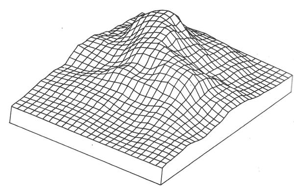
Fig 12.3: An array plotted with hidden line elimination
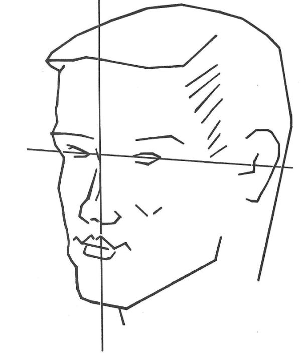
Fig 12.4: A picture output produced by the SOLIDS animation program
CURRENT AND FUTURE DEVELOPMENT
Additional areas of development concern techniques of curved surface representation or outlining, simplified methods of programming articulated motion, and improvements to a data generator program now being used for simple geometric shapes.
Fig 12.5: Animator's ambition - to employ the computer to draw cartoon characters - is realised through the SOLIDS Animation Program of William D Gettis
Fig 12.6: Illustrations taken directly from a Calcomp plotter showing lip positions of a character representing a computer.