

N Burtnyk and M Wein
1974
Focal Press
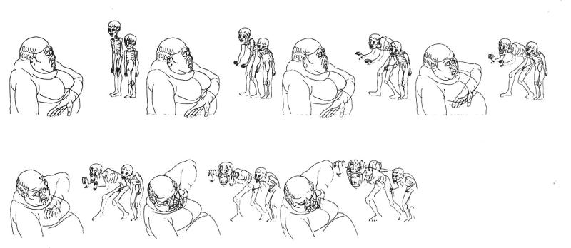
Fig 6.1: Selected images from a sequence in La Faim, by Peter Foldes, produced for the National Film Board of Canada using the NRC computer animation system. This shows the capability for full character animation
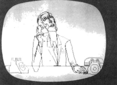
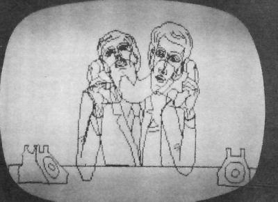
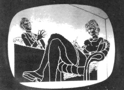
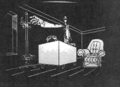
Fig 6.2: Selected frames from La Faim photographed from the real time playback TV display. Parallel sequences are merged into a composite sequence (first two images). Selected areas may be filled in to build up levels of visibility which remove transparency of the line drawings (last two images).
The potential role of computer graphics in generating animated film has been widely investigated in recent years. In order to simplify the task of computer programming, special animation languages have been developed for specifying an image sequence to be generated by a computer. Although this approach to computer animation has provided some form of organization and control of the specification of image sequences, the computer remains out of reach to most animators because of the communication difficulty. An animator's ideas mainly involve pictures and their motion. Thus it is appropriate that the communication of ideas between the animator and the computer should be largely through pictures. Our interactive computer-controlled graphics system allows the animator to develop pictorial sequences directly on a cathode-ray tube display, without forcing the animator to become a computer programmer.
The implementation of computer-assisted keyframe animation is based on techniques that have been developed in conventional cel animation. The animator prepares the artwork required for the sequence by drawing directly on the CRT graphics display. Once these picture components have been drawn, he may manipulate them in position, orientation and size and assemble them to form cels analogous to those in conventional animation. A number of these cels may be further assembled to form a composite cel which is used as a key frame in a sequence. A series of key frames is thus created and stored in the computer. In addition to the picture, information about the kind of motion and the number of frames from the previous key frame is specified by the animator. During playback of this sequence, the inbetween frames are computed by interpolating between key frames, and are displayed at the cine rate on the cathode-ray tube display. This previewing is available immediately after the sequence is created, thus allowing rapid assessment of the motion and timing of the sequence.
INTERACTIVE GRAPHICS FACILITY
Our computer graphics facility is based on a small high-speed digital computer, driving a cathode-ray tube display. The processor has a memory capacity of 16K 24-bit words, supplemented by a disc file storage unit.
The graphics software consists of a family of interactive graphics programs that create, modify and manipulate picture data. Of these, the major programming package is used for interactive three-dimensional (3D) graphics. Within this package, pictures are represented by a sequence of connected points in space, with each point specified by three co-ordinates and the connecting lines coded to be intensified or not as required to describe a three-dimensional object. Prior to generation of a display frame, the program applies three-dimensional rotation, position and scale information to the picture data to determine the current view of the 30D object. From this viewing direction, a two-dimensional projection (perspective or parallel) is computed and displayed on the CRT. If several objects are being displayed, their viewing directions may be controlled independently. Rotation about any axis as well as position and size of each object is dynamically changed by operating the appropriate input controls. These controls are sensed once per frame and used to update the three-dimensional rotation, position and scale information that is being applied to the picture data before projection and display. In this way, an immediate visual response to the animator's control is produced.
The primary input devices are a light pen, a keyboard, vertical and horizontal thumbwheel encoders, footswitches and a mouse - a two-dimensional position encoder which can be moved about on any horizontal surface and thereby control position on the CRT (Fig. 6.3).
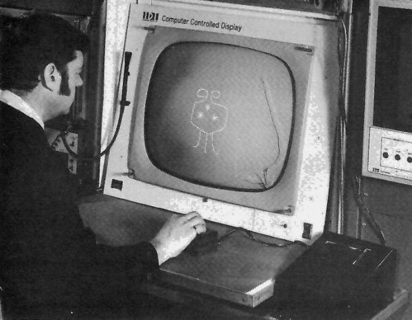
Fig 6.3: Free hand drawing with the mouse - a two-dimensional position encoder.
The artist sketches and manipulates picture components in three dimensions with these devices. He may combine these sketched components with computed geometrical forms generated by the computer. All picture components may be saved in the picture library for use at any time.
Complementing the 3D graphics package is a group of auxiliary graphic routines that create and modify picture data. In particular, a free-form sketching program allows the animator to create freehand drawings using the mouse-as a drawing pencil, as shown in Fig. 6.4a. Other routines that operate in conjunction with the 30 package allow distortion or shaping of picture components by modifying the co-ordinates of selected points within a picture. Using the mouse to control the position of a cursor, the cursor may be connected to any point in a picture and pulled in any direction, moving the selected point with it ( Fig. 6.4b). Alternately, the cursor may he replaced by a circle or square of variable size. It is now used as a shaping tool. Again its position is controlled with the mouse and pushing it against selected parts of a picture causes the picture to distort into the shape of the tool (Fig. 6.4c). In addition, a variety of computed distortions (e.g., sinusoidal, inverse distance from centre, square of distance, etc.) may be applied to the entire picture by selection from an assortment of distortion functions.
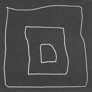
Fig 6.4a: A free-form sketching program allows the animator to create free hand drawings using the mouse as a drawing pencil.
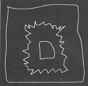
Fig 6.4b: Using the mouse to control a cursor which may be connected to any point and pulled in any direction.
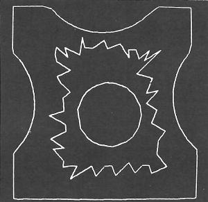
Fig 6.4c: The cursor may be replaced by a circle or square and used as a shaping tool with which to distort the picture.
The main form of communication between the animator and the system is by means of selections from lists or menus that are presented on the CRT screen. In the 3D graphics package, numerous lists are built into the program to permit the selection of the desired operating mode. By making a selection, the animator can initiate or activate input control functions for picture handling and manipulation. For example, he can assign to the two thumbwheels the function of positioning a picture element or a rotation about any desired axis, or scaling the picture element. A selection is made either by turning the thumbwheel and thereby causing a cursor to move to the desired item on the list or by pointing the light pen at it. Most users prefer the thumbwheel rather than the light pin.
Communication through lists is also used to provide access to the disc library. The disc filing system provides a powerful facility for saving and retrieving both picture data and programs. Whenever a picture is being saved the animator types a name he assigns to the picture and the name is added to the list displayed on the CRT. The lists of picture names differ from the control lists mentioned earlier in that they are not built in, and a new empty list can be created at any time. By entering the names of other lists to any list a hierarchical structure of lists is created which allows searching and browsing. One quickly learns to organize his lists, such that all the related items are on as few lists as possible - so that the desired item can be located quickly.
PREPARATION OF PICTURES
The technique of key-frame animation involves the creation by the animator of isolated frames at key intervals during a sequence, with the in-between frames to be computed by interpolation. Since the pictorial content of successive key frames to be computed by interpolation. Since the pictorial content of successive key frames need not bear any particular relations to one another, a wide variety of transformations is easily produced. In Fig. 6.5a, five extreme leg positions were drawn and assembled to create five key frames for one walk cycle that could be used repetitively. These pictures were drawn in a particular way to insure that the transformations between key frames would simulate in-between positions of the legs. On the other hand, only two terminal key frames were used in the sequence of Fig. 6.5b. Regardless of the order in which lines may have been drawn in preparing these key frames, the in-between transformation would be smooth, though possibly quite random. In the actual illustration, each key frame consisted of five cels with control led transformation between cels.
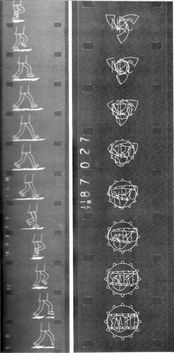
Fig 6.5: Five extreme leg positions were drawn and assembled to create five key frames for one walk cycle that could be used repetitively.
Starting with a script and a story board, the series of key sketches that will progressively depict the action must be planned. These keys will include the extremes of all movements, since they will be used as the terminal points for interpolating the in-betweens. Once all the key frames have been established, the animator can begin preparing his picture components or eels by sketching the images directly on the display. As these picture cels are created, they are saved in the picture library for use at a later time. Each picture cel is interpreted as a 3D shape so that its viewing direction may be manipulated as required. A composite cel for a key frame may be assembled by overlaying a number of individual picture cels. Pictures for subsequent key frames may be partially or completely redrawn, or alternately, may be derived by notification of existing pictures using one of the distortion routines.
GENERATING A SEQUENCE
Communication with the computer during generation of a sequence is maintained through the menu that may be recalled by depressing a keyboard button. Selections from this menu initiate the various operations that are required in specifying key-frame data. These functions are listed in Table 1.
| Items on Menu | Functions |
|---|---|
| Return | Returns to normal display of picture. |
| Start Seqn | Stores the current picture as a reference start frame. |
| Interpolation | Enables the assignment of an interpolation law to each individual cel in the current picture. |
| Set Frame | Allows setting of the number of frames from the previous key frame. |
| Store Key | Stores the current picture as a key frame on disc or magnetic tape. |
| Terminate | Terminates the sequence. |
| Read Key | Brings in the next key frame from disc or magnetic tape. |
| Auto Read/Write | Transfers remainder of sequence from the input to the output device. |
| Manual Write/Read | Stores current picture as a key frame and brings in the next key frame. |
The last 3 items are used for editing.
Table 1: Operations in Key Frame Generation
The first key frame in a sequence is stored as a reference start frame. For all succeeding key frames, separate interpolation laws are assigned and stored for each individual picture or cel in the composite cel, as well as the number of frames from the previous key frame. During playback of the sequence, each picture cel transforms into the corresponding cel of the following key frame, determined by the order in which they were assembled into the composite cel, i.e., the first into the first, the second into the second, etc. (Fig. 6.6).
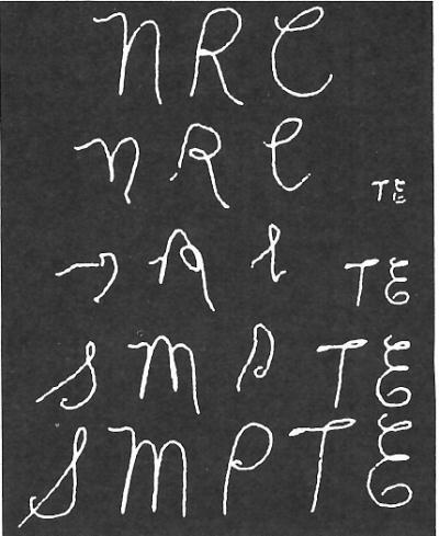
Fig 6.6: Only two terminal key frames were used in this sequence.
When the number of picture components is reduced from one key frame to the next, the excess picture components disappear. When this number increases, the corresponding new images are added to the sequence. Most often, picture components are introduced without being displayed in the previous key frame and then intensified in the next key frame to provide a starting reference position for the additional picture material. If this step is omitted, the new images grow out from the centre of the screen as in a zoom-in.
In order to maintain control over the way individual cels from each key frame transform into the corresponding cels of the succeeding key frame, the interpolation process or mapping is performed on a stroke-to-stroke basis between cels. Since all pictures are drawn as a string of intensified or invisible lines, a stroke is defined as a succession of visible line segments terminated at each end by an invisible line segments terminated at each end by an invisible line. During playback, the number of strokes in each cel is determined by scanning the picture data. The stroke counts in each of the cels in the source key frame are temporarily modified to equal those in the destination key frame by concatenating or subdividing strokes as required. During interpolation, the points within each stroke in the source picture will map toward the points in the corresponding strokes of the destination picture, with pseudo points being generated to equalize the point count. For example, if a picture cel, A, in one key frame consists of three strokes and the corresponding picture cel, B, in the next key frame consists of five strokes, then the first two strokes of cel A will subdivide to generate a stroke count equal to that of cel B as shown in Fig. 6.7. If, on the other hand, the two key frames are interchanged in sequence, four strokes from cel B will combine in pairs to produce the same picture sequence in reverse order. This use of stroke mapping allows the animator to design particular transformations into a sequence by choosing the number and the order in which strokes in each picture cel are drawn. Separate strokes need not be visibly separated: as long as each stroke is terminated by inserting an invisible line of any length before the next stroke is drawn.
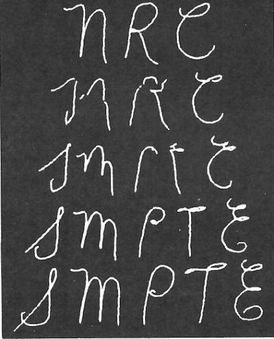
Fig 6.7: The interpolation law applied to a figure in various combinations.
Both the number of in-between frames and the interpolation law control the rate of mapping during interpolation. For straight line mapping, the interpolation law may be set to produce motion between two key frames that is constant, accelerating, decelerating or a combination of acceleration followed by deceleration. If desired, each of the above laws may be assigned for only the horizontal or vertical component of motion while the other component is linear. On the other hand, acceleration and deceleration may be applied in opposition to the horizontal and vertical components of motion, producing a constant angular velocity along a circular or elliptical path. Some of these interpolation laws are illustrated in Fig. 6.8. In addition, other laws that do not involve mapping, such as Blank, Substitute, and Delete, may be assigned to any picture component as the sequence demands.
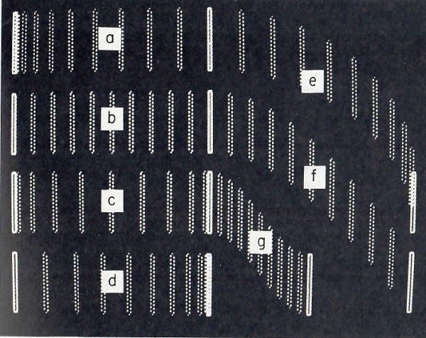
Fig 6.8: Sequences which are designed so that the outlines completely enclose areas can be scanned to produce animated mattes.
FILE HANDLING
The key-frame sequence is stored on magnetic tape or disc to form a data file that may be modified or revised after previewing. These files may be generated in either the full 3D format to maintain the capability of picture manipulation, or as projected 2D co-ordinates. The simpler 2D format is necessary for previewing a sequence where the computation time must be kept to a minimum in an attempt to maintain the cine frame rate, that is the computer's real operating time per frame to be shorter than 1/24s. When the computation and display time become excessive, as for a detailed picture, an alarm is sounded to warn that the standard cine rate cannot be maintained. This speed limitation is circumvented by displaying every 2nd or 3rd frame only at correspondingly reduced frame rates until the rates of motion corresponding to the cine rate are recovered. On the other hand, the overall timing of a sequence may be readily slowed down to allow a closer examination of the action. During filming, the sequence is played back at a slower rate using a synchronized camera.
The 3D file is maintained as the current working version of a sequence. Since this format is identical with that of the data structure within the computer memory, both the pictorial content of any key frame and the assignment of interpolation laws and frame counts may be easily revised. This includes rearrangement, substitution, insertion and deletion of picture material in the sequence. From the revised 3D file, a new 2D file may be quickly regenerated and previewed to assess the motion and timing of the revised sequence.
Typically in a sequence, as few key frames as possible are used. The motion of picture elements between key frames is provided by the playback program and is smooth. Often the animator wants to insert an intermediate key frame for one picture element to break its rhythm and yet maintain smoothness of motion for other picture elements. A difficulty arises in that he must specify the position of all elements in that key frame, and may destroy the smoothness of motion for all the elements. It is most convenient to develop the sequence as several parallel sequences, with key frames at different intervals in each sequence. These individual 2D sequences may then be merged into one sequence. On the other hand these parallel sequences are often not merged and are filmed separately, to generate separation prints for multicolour printing in an optical printer.
A utility program is also available for file management of both 2D and 3D files. This permits the transfer of files from one storage device to another and the listing of the contents (key-frame number, frame count, number of cels, interpolation laws, etc.) of a key-frame file. In addition, several 3D files may be combined into a single sequence, and key frames may be rearranged if no changes within the key frames are being made. This utility program together with the key-frame generation package offer a facility for editing sequences thoroughly before they are transferred to film.
ASSESSMENT
A short film has been made to illustrate the potential of the computer as a tool for the animator. In this film, the way in which the computer is used in the technique of key-frame animation is described. The music in the soundtrack was also generated on the same interactive computer facility.
There are three major limitations in the capabilities of our animation system. First, considerable difficulty may be experienced in attempting to provide good continuity in rotational motion without an excessive number of key frames. One way of overcoming this difficulty would be to incorporate rotation with the playback process, and preferably in the full 3D format. That would increase the computation time per frame, however, by a large factor.
Secondly, in our present system, the images for the key frames are limited to skeletal or outline drawings. Although this may suffice for study or experimentation with motion sequences, the quality of the image does not meet commercial film requirements except in special applications. If, however, sequences are designed such that the outlines completely enclose areas, a scanning process can be applied during filming to produce animated mattes such as Fig. 6.9. We intend to extend this capability of area painting and to investigate the problem of controlling line thickness.
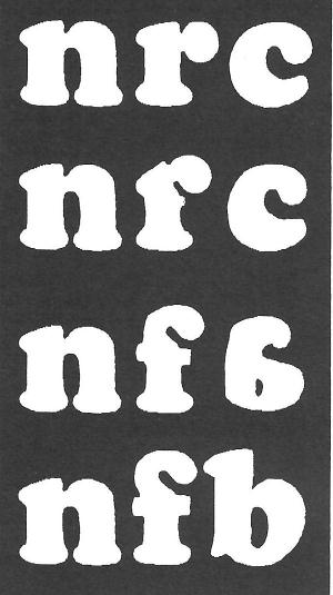
Fig 6.9: Programed raster scan, applied to a controlled transformation sequence produces an interesting travelling matte or super.
Finally, the delay that is introduced by computation and display during playback increases directly with picture content making previewing less satisfactory for detailed pictures. As a possible solution to this problem, one could convert the information to video format and record it on a helical-scan videotape recorder with a slow recording rate (e.g., Sony Model EV-330 TLV). The tape would then be available for immediate playback at the normal rate.
In addition, the use of the mouse for freehand drawing has not been entirely satisfactory. A data input tablet will be added to the system in the near future. The data tablet will permit drawing with a ballpoint pen on ordinary paper while the computer stores the picture information.
Visiting artists have been encouraged to experiment with our animation facility to help assess its usefulness in their creative work. Their response has been generally favourable in terms of adjusting to this new medium. Although no knowledge of programming is necessary, the animator must become familiar with the overview of the system, and with the role of the disc-filing system to his commands. The design procedure for creating a sequence parallels conventional animation, and typically, useful work can be produced after several days of practice. Opening sequences for several industrial promotional films and for network television shows have been produced using this system.