
This paper was first presented at Film 73, and more recently at the first BKSTS/John Player Lecture at the National Film Theatre. It describes a new computer animation system developed by the author. The original lecture was accompanied by some 120 slides as well as films; the talk has therefore had to be adapted for publication.
As you may have gathered, Antics is the name of a computer animation program. Eventually I shall get around to describing it, but since not everyone is familiar with the principles involved. I shall first try to cover some background.
Now, the first important thing is that making ordinary animated films is an enormously laborious business. Something like 90 or 95 per cent of this labour is involved with the mechanical task of turning the initial creative design work into a finished film. This initial creative work usually begins with a storyboard, a sound track recorded on magnetic film, and some basic character designs. A bar-chart is produced describing the movements and timings of each scene; and finally, layout sketches and key drawings are made in pencil on paper which define the overall design of each scene. With this, the creative design work is really finished. From this point on everything else is sheer mechanical labour. The key drawings have to be in-betweened, and each of these has to be traced onto cel and painted by hand. An elaborate dopesheet has to be drawn up giving precise camera instructions for every frame of film. Eventually you end up with a big pile of drawings representing hundreds of hours work and probably worth its weight in gold. These have to be photographed one by one on a rostrum camera and at last you have a negative ready for printing.
Not only is this process laborious it is also 60 years old. In all that time the basic principles of drawings-on-celluloid laid over a background have not changed.
Right then! If 95% of this work is mechanical, you might think it's about time we had a machine to do it. You might also think that since computers seem capable of doing so many other miraculous things, that the computer should be the right machine for the job. Certainly, if we had such a machine, most animators would gladly throw their peg-bars out of the window.
So far, this hasn't happened, and yet a tremendous amount of work has been done on computer animation especially in the United States. So what's the snag? Well, if you think at all about computer animation, you probably think of something like these ... [slides shown]
So far, nearly all computer animation has been of two distinct kinds. Firstly, simulation. Here the computer is used to perform mathematical simulations of processes which are too complex to study in any other way. Scientific simulations of this kind are an enormously valuable new dimension to many fields of study. Many of these films can be visually exciting too, of course, and do find their way into some educational films. However, this use is far too specialised to be of general use to graphic designers and animators.
The second type of computer film is concerned with artistic exploration, such as the well-known ones by John Whitney, Bruce Cornwell or Lillian Schwarz. Usually what's involved here is some kind of fusion of abstract geometrical elements with complex periodic rhythms of movements: in many ways this makes it a visual analogue of music, and it is certainly true to say it adds an important new dimension to the exploration of art and visual perception. However, this is also a rather specialised field, and still fails to be of general use to graphic designers and animators.
The appeal of animation as a medium lies in the fact that the designer has very great freedom to create whatever images the imagination desires. This freedom, in fact, is the main reason why animators are prepared to undertake such tortuous labours. So, unless the computer can act at least close to matching this freedom, the majority of designers and animators are not going to be whole-heartedly interested.
The problem is, then; how can the computer manage to give us this freedom? To answer this we have to know a little bit about how it works. By far the most common method of making computer films is by use of an uninformative-looking large grey box called a microfilm recorder, such as the Stromberg-Carlson Datagraphix 4020. Inside this box is a movie camera which is focused on the screen of what is basically a highly-specialised Cathode Ray Tube. If you want to draw pictures with this apparatus then there is really only one thing that this machine will do. It will draw a straight line.
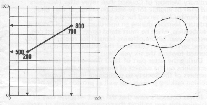
A single straight line can be defined geometrically by two pair of numbers on a co-ordinate grid (fig 1a). The X and Y deflections of the CRT are controlled within a range of 0 to 1023; so the screen is equivalent to a sheet of graph paper with a choice of over a million different points. Any straight line like this is called a vector
On the right of the SC-4020 is a magnetic tape unit. In the computer world, magnetic tapes store nothing but numbers; the SC-4020 will read numbers off the tape and interpret them as co-ordinates on the grid, and so record them on film as straight lines. This immediately explains why abstract geometrical shapes are so popular with computer film-makers; if you are dealing with squares and triangles you need very few numbers to build up a picture; free-style drawings, however, usually have a lot of arbitrary curves. Since the machine will draw only straight lines, curves have to be approximated by drawing a whole sequence of short straight lines, and this means you'll need an awful lot of numbers (fig 1b).
With the microfilm recorder, then, the task of making a film reduces to the following problem: the programmer has to get a computer to generate a data-tape containing just the right numbers needed to draw the images he wants. This is a standard computing operation, and in theory at least, could be done on any computer.
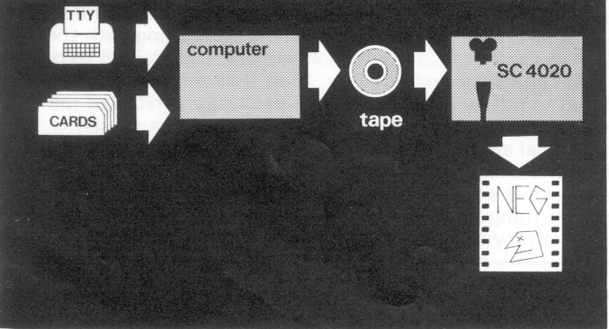
Figure 2, then, shows the minimum configuration you will find being used in most computer animation establishments. A computer generating numbers on a magnetic tape, and a microfilm recorder plotting these numbers as straight lines on film. This configuration is so common that I tend to refer to it as traditional computer animation.
To get any further we now have to understand two major limitations of this equipment, and then take a quick look at some of the attempts that have been made to overcome these limitations.
The first one I've already mentioned, the limitation of only being able to draw straight lines, Therefore. people have tended to produce films consisting only of outline drawings, since this is the simplest thing to do, and is usually quite adequate for applications such as scientific simulations.
The other limitation is colour, The CRT screen of the SC-4020 draws lines of only one colour - and this is a rather violet-tinted white. Attempts have been made to record onto colour stock through filters, but this rarely gives good results. Whatever the reason for this may be, the outcome is that people who have wanted to add colour to their films have usually had to resort to optical printing in the processing laboratory, and that makes it an expensive operation.
There have been a number of attempts to overcome both these limitations; I want now to describe briefly just three of these. The first is the sledge-hammer approach, This was first developed at the University of California at Los Angeles, as part of the Apollo space programme, and more recently a similar system has been developed at Utah, The system produces full-colour pictures on a TV display. The purpose is the simulation of the view from the window of an aircraft or space-craft; basically what happens is that any chosen environment is fed into the machine as a set of plans and elevations, Any viewpoint can be selected and the perspective view from that point is displayed on the colour monitor. In front of this is a joystick control which the viewer can operate - moving the joystick causes the viewpoint to move in a corresponding direction and speed, The system is so powerful that successive perspective frames can be displayed continuously at live - action speed. This is the sledge-hammer approach, because vast sums of money were spent developing special equipment for this system. Unfortunately, the cost puts it way out of bounds for ordinary film-making purposes at least for a good few years to come. A simplified version of this system has just been developed, however, called Syntha Vision. This offers a commercial computer animation service at very competitive rates, and does achieve high quality full-colour results. Being a 3-dimensional system it does not work from drawings, but from descriptions of 3 dimensional solids, which is a much trickier business. So far, the system is limited to combinations of simple solids such as spheres, cones and blocks, with the result that the pictures produced although very realistic, all seem to have a similar toy town quality to them.
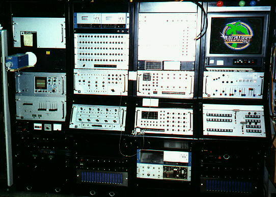
The second approach is already well-known; the Computer Image Corporation. Their approach is different from any other in that it is based on a completely different starting point. Just about everything else that's been done under the heading of computer animation has involved the use of an ordinary digital computer. Almost always these have been perfectly standard general-purpose machines being used for the normal variety of computer work. Computer Image, however, set out with the aim of starting completely from scratch to design a computer specifically for animation. The whole process of converting pictures to numbers, manipulating the numbers, and then converting them back into pictures seems an unnecessarily precise way of going about things. Computer Image's aim was to produce a system that would be of general use to designers and animators, just as I've already described. They realised that rather than attempt to use a digital computer, it should be possible to take a much more direct approach by working with video images in analogue form. The first machine they produced is Scanimate. This uses a TV camera to input basic design images; colour is added synthetically and the result displayed on a TV screen. In front of this is a control panel. By manipulating controls on this panel the animator can squeeze, stretch, zoom and otherwise distort the image in a variety of ways; when he is satisfied with the result, he can then record the whole thing at live-action speed direct onto video-tape. This approach is therefore quite revolutionary, since it does achieve instant full-colour animation. Not surprisingly it has had quite considerable commercial success, particularly for TV titles and special effects.
Scanimate Example: Beatles
Scanimate in Operation
Scanimate itself, however, is still a fairly limited system, since it is not possible to have more than five independently-controlled elements on the screen at once. Computer Image have produced a much more sophisticated machine called Caesar, however, which is capable of handling up to 13 elements, and can produce full-colour character animation. Unfortunately, the last news I had was that they had run into difficulties with this machine. Also, because of development costs, even the simple Scanimate machine is quite expensive to use, so Caesar is likely to be more so.
So the situation looks like this: either we have to wait for Computer Image to come through with their advanced video systems, or else we go back and take another look at the digital computer. At first sight it would appear that the analogue video approach is the winner. It operates directly: There is no programming required; you just twiddle the knobs and get results immediately, in real-time. In comparison with this, the digital approach seems very heavy-handed.
However, if we look a little bit into the future, ten or twenty years, say, we can see some likely changes. Firstly, of course, is the fact that each new generation of computers is faster and cheaper than the last; so that where at present you would need to have a specially-built piece of analogue equipment, in the future a general-purpose digital machine will be able to do the same job. As you probably know, this is already happening; digital techniques are being used in telecommunications, and particularly significantly, in TV standards conversion. Digital TV is not so very far off.
There are many reasons why we can expect that high-speed digital techniques will ultimately win out. Firstly, digital signals are easier to transmit from place to place, because problems of noise and distortion are easier to overcome; secondly is the generality. By reducing all problems to simple yes/no or on/off decisions, you have the possibility of handling all kinds of communications needs within a single unified network; this promises eventually to simplify and reduce the technological resources required to a level where every individual in the community can have access to such a network.
All this may seem remote at the moment, but it does mean that a purely analogue approach probably has a limited future. Another indicator is that Computer Image themselves are already making increasing use of digital techniques in their latest developments; we can already foresee a fusion of the two approaches. And finally, of course, the new development of Syntha Vision indicates that digital techniques are already beginning to become practical.
So, the question I just asked was - do we wait for Computer Image to develop advanced video systems, or do we look harder at digital techniques? Well, I never like to sit around waiting, so of course I'm going to take you back to the digital computer.
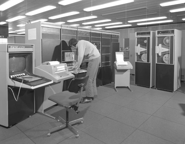
Since Scanimate came on the scene, there has been a new approach taken by digital computer animators. This uses quite a small computer, such as the PDP-15 shown here (fig.3), and a black and white TV display. Being a small computer, you can afford to use it exclusively and continuously. Therefore, you can hook it up to the TV display and work interactively with it, just as you can with Scanimate. Several people have tried this approach for animation. The first was Ron Baecker at MIT in the States; similar work is now being done here at the Atlas Comp Laboratory, Chilton, near Oxford. However, the emphasis has been on getting real-time playback. Consequently, only very simple line images can be animated - and that means the results are still much too crude to be of any general use to animators. This, then, is where we at Grove Park Studio came in. In December 1971 I wrote in this journal that computer animation had still failed to produce a system that animators could make widespread use of - the only exception being Computer Image. Then we heard that Computer Image had run into delays, and it began to seem as if the peg-bar and the cel would continue to rule the animator's hand for a long time to come.
However, I was becoming more and more convinced that the computer's lack of success was due simply to one thing - lack of communication. I became convinced that the problem was unsolved simply because no-one had taken a general approach. Computer animators were split - the designers didn't know programming and the programmers didn't know animation - and in any such situation there are always fundamental barriers of communication and perception that limit the possibilities of co-operation.* It was then that I met Colin Emmett at the Royal College of Art, who had already been experimenting with the SC-4020 at the Atlas Computer Laboratory. I explained to him why, as an animator and designer, I felt that computer animators had failed to satisfy my interests. He promptly persuaded me to learn Fortran programming and tackle the problem myself.
* There is a discussion of this problem in relation to visual media and education in the author's article "Viscom-71 - when is a Revolution Not a Revolution?" in the October 1971 issue of this journal.
By traditional animation methods, a single frame image is going to take quite a long time to produce; on average - anything from 10 minutes if it's simple, up to possibly an hour or even more. So the first thing that seemed wrong was the seemingly universal insistence on trying to produce animation in real-time. After all, if we could get even one frame a minute, it would be a tremendous improvement. This would be worth trying, even if it proved uneconomical. At least we could say well, just wait ten years..; but if the cost turned out to be practical, we would have a pleasant surprise.
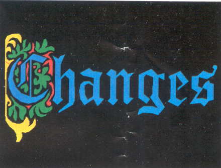
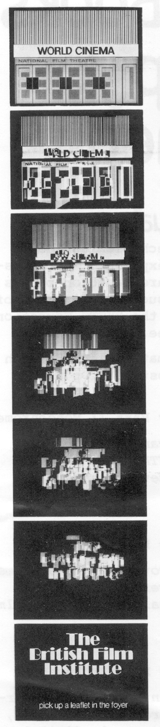
Colin Emmett invited me to join him working at the Atlas Laboratory. This meant we would be using a system that I have already described as traditional - based on the SC-4020 microfilm recorder. At the outset, therefore, we were limited to using existing standard equipment. Now, this was about April 1972, at which time we had just begun making a short conventional cartoon film for the British Film Institute. We decided to see if we could use the Atlas Computer to produce an end title for this film that would match the design of the film overall with some simple animation of the kind Scanimate would produce. Since the SC-4020 can only draw straight lines, solid colour areas have to be scanned with lines, like a TV picture. After a little experimenting we chose a scanning density of 200 lines across the screen; we drew the lettering design on graph paper and read off the numbers by hand; this was a bit tedious, but actually it only took a few hours, so it wasn't so bad. We added colour by optical printing, so the final result looked like this... (fig 4)
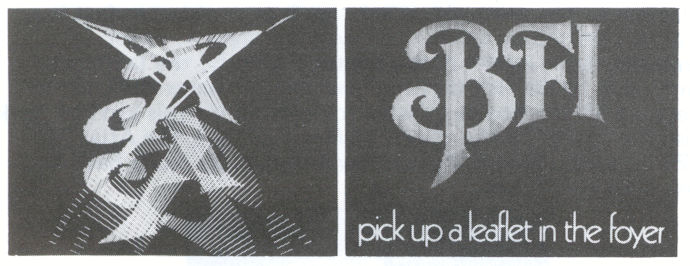
Getting it to move was very simple. We wrote a little program that dispersed the scan lines to the top and bottom of the screen, and ran it in reverse. Now let's look at the result; I'll make no apology for showing the whole thing, since you can see it does fall into its place in the film quite well; even though it has obvious differences. [Film shown:" The Dream of Arthur Sleap "]
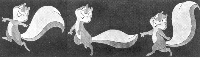
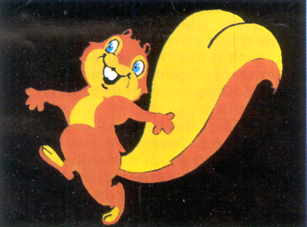
At the end there, as you saw, we also put the Grove Park Studio squirrel logo through the same program.
Two things came out of this experiment; firstly, we proved we could get a satisfactory coloured image from the SC-4020, and to our great surprise, it was very cheap, taking only a little over 2 minutes' computer time to produce, which costs practically nothing. In fact, the major cost was optical printing. This came to £50, which is rather a lot for two short sequences. However, it was an encouraging start.
The second result was quite accidental - one of these fortuitous accidents that happen from time to time in experimental work. You may have noticed a jump in the colour density of the BFI lettering at the end of the animation. This is because during the animation each line (or vector) of the image was being drawn twice; in the final image, however, it's only drawn once.
Originally we planned to make an intermediate optical print on high-contrast stock, but it couldn't cope with the variation in density caused by vectors being drawn on top of each other. Instead, we had to use fine-grain stock, and the variation in density was faithfully reproduced. This showed us that over-writing vectors might well be a practical basis for producing half-tones. However, the complication and expense of optical printing seemed a fundamental barrier, so this clue was not followed up until last autumn, when it occurred to us to wonder if the Technicolor triple-printing process could be used.
In the original form of Technicolor 35mm film they had special cameras which contained not colour film, but three separate rolls of black and white film that ran simultaneously. The image in the lens was split up by prisms into three identical images, one for each film; then one had a red filter over it, one a green, and the third a blue - thus the colours in the original image were split into their primary colour components and recorded as three colour-separation negatives. This, of course, is the same principle now used in colour TV cameras. This principle could be applied very simply to the SC-4020. If we specify a colour in terms of the relative amounts of the three primary colours that it contains, we could generate three black and white separation negatives directly, without having to use filters at all.
I went to see Bernard Happe at Technicolor who was very interested in the idea; although triple-run cameras are long obsolete, colour separations are still used in dye-transfer printing, so that triple-printing is still a standard operation, and indeed was already expanding into the new area of Vidtronics. The printing operates directly from three B+W separation negatives, without any dupes or intermediates required; the negs must be 35mm and perfectly registered of course; the print may be 35mm or 16mm, and the cost is not so very much more than the cost of an ordinary rush print from an ordinary camera negative. Luckily enough, although there are several microfilm recorders in various places in this country, the one at the Atlas Lab is the only one fitted with a high-quality pin-register 35mm camera; also the little Grove Park squirrel sequence had already proved the excellence of the registration, so we went ahead to do some full-colour tests.
Because our BFI sequence had taken much less computer time than we feared, we decided to increase the definition to 512 lines. We plumped for a density range from 0 to 8, which gave us this grey scale [ slide shown] . The density goes logarithmically 1,2,4,8; so there is the equivalent of one stop between each grey; there are also four intermediate densities available. This range combined on all three separation negatives gives a total range of 729 colours including black and white. Here are some colour patches showing just a few of the possible colours. . . [slides shown] . . . notice that there are quite a few good pastel shades as well as the more highly saturated colours.
So we now had a good range of colours, and furthermore we could get a print in a single step direct from SC-4020 camera negative. Selecting a colour is done in the same way as buying paint in a decorating shop. We have colour samples arranged on a chart; you simply find the colour you want and read off the code number, which gives the component densities of red, green and blue - so black is 000, white is 888 and pure yellow, for example, is 880.
The next step was to get a complete colour drawing. This was not so easy. Generating a scanned rectangular patch is one thing but scanning an area of ANY shape chosen at random is another. So, in November last year, we went back to the Atlas Lab again to tackle this problem.
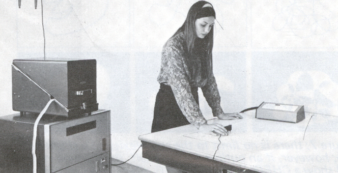
Now, the lab already has a machine for turning line-drawings into numbers. This is the D-MAC pencil follower. (fig 5) As you can see this is basically a large drawing table; all you do is stick down the drawing you want to feed in, and trace round it with a special magnetic pencil. Follower mechanisms under the table detect the position of the pen, and this is displayed as a pair of co-ordinates and simultaneously punched onto paper-tape. Although it sounds a little crude, it is actually extremely precise - it's accurate to 1/10th of a millimetre over an area one metre square - and it's also very quick and easy to use. Even a very complicated drawing takes only about 20 minutes to feed in. For our purposes, however it was not sufficient just to feed in a load of points. There had to be some way of organising the points so that the computer would know which area was to be what colour.
This becomes a simple matter provided one rule is observed; every patch of colour must be defined by a complete outline - a single closed curve: this, however, may be as complicated as you like - simply it must be continuous, and it must end up where it began. Actually, the Antics programme takes care of this hooking-up automatically - for example, as a test we fed in 40 completely random numbers. These were automatically interpreted as closed outlines and this was the result. . . [slide shown]. However, we're getting ahead of the story.
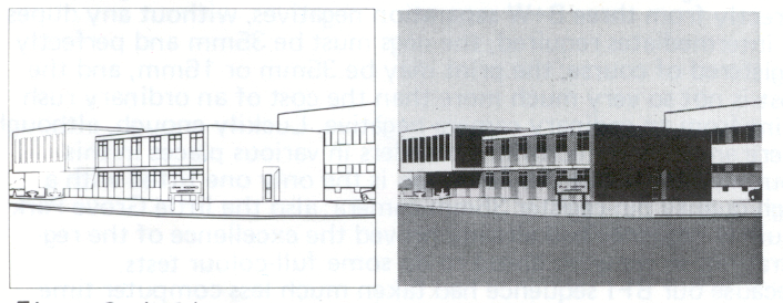
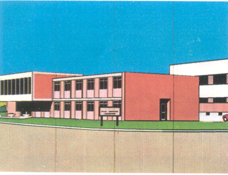
The point is that it's the boundary of the colour area that has to be drawn; if a line is a boundary between two colour areas then it will have to appear twice, once in each of the two area outlines For our first full-colour test we made a drawing of the Atlas Lab itself. traced from a photograph (fig 6).
The remaining step was to get the machine to convert the outlines into solid areas of colour. This was actually our most difficult problem. Although it sounds simple, it is actually full of pitfalls for the unwary programmer. However, we realised that if we could make it work quickly, accurately and reliably, it would then be no trouble at all to start producing animation. Consequently we decided to go full steam ahead with the goal of making a complete working animation system; in January this year I began working a regular two days every week at Atlas, with scanning as the first major problem.
It took till the end of February to get it working perfectly. The principle is like a switch: you work up from the bottom of the screen - when you cross an outline, you start drawing a line. When you cross it again, you stop. It doesn't matter how many times the curve crosses itself. if it's a closed curve, the number of boundaries you cross is bound to be an even number.
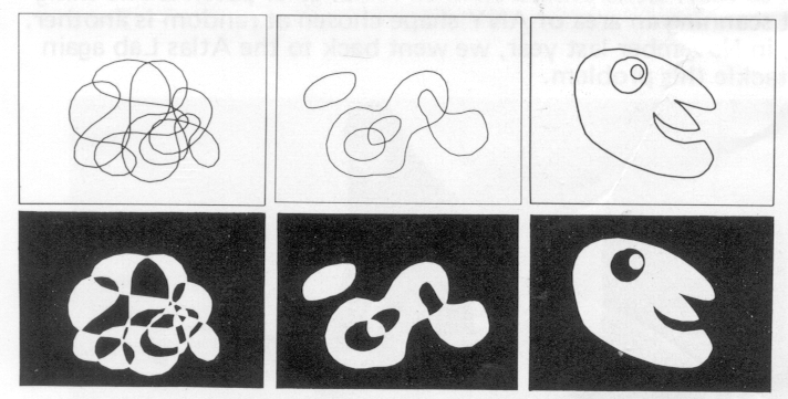
It also means that if you have one outline inside another, you will get the effect of one reversing out of the other (fig 7).
If outlines cross each other, or if it crosses itself, you get what's called the chequerboarding effect. This effect is quite important. The three outlines in the right-hand picture of figure 7 are scanned together in a single operation. This means you do not need to treat the black hole as a separate area; you don't have to specify it as black and this turns out to be very useful. In the Antics program, information is organised at 5 different levels: the most basic unit is the single point; and a set of points of course makes up a single outline. Next, however, any number of separate outlines may be grouped together and this is called a figure; this is the basic unit for scanning. All the outlines in a single figure are scanned together, giving the chequerboarding effect if they overlap in any way. A figure is therefore the basic colour unit - you specify one single colour for each complete figure. Next step up is the character set. This consists of any number of differently - coloured figures which are animated together as a single unit - such as a cartoon character, for example. Finally, you may have any number of character sets on the screen together to form a complete picture. Figure 6b shows our first half-tone image, produced from the drawing of the Atlas Laboratory. Although we weren't particularly aiming for photographic realism, it is remarkably photographic in quality. Colour separations are produced automatically, and so we got our first full-colour picture (fig C1).
The synthetic colouring gives it an interesting quality - a sort of super-real quality, like a hand-coloured postcard. However photographic realism is not really the aim of the system - we only did this just to see how far we could go.
Now we were able to start generating images. Here are some examples of the kind of image we can work with. [various slides including figs C2 to C6.] These results were every bit as good as we hoped. The slides, by the way, are actual frames cut from an ordinary 35mm rush print made direct from the SC4020 negs so this is the quality of image that can be got on the screen. There have been only two major problems with image quality.
Firstly, a peculiarity of the SC-4020 is that short lines do not always come out with the same density as long lines. This means that sometimes the colour density varies from one part of the image to another. Usually, this discrepancy is not great, but sometimes the plotter has an off day and it can become objectionable. Secondly, some of these pictures have thin black lines down that look like scratches. Actually they are not scratches, but discrepancies on the SC-4020. Unfortunately, the SC-4020 at Atlas is over ten years old. It's design is even older; in fact it runs on Thermionic valves - not even transistors - which in computer terms makes it an antique. Basically, the faults are simply due to the fact that the machine was never designed to operate with the degree of accuracy needed for this kind of work. It is only thanks to the efforts of David Greene, the Atlas SC-4020 engineer, that in the last few weeks these faults have now been pretty-well cured.
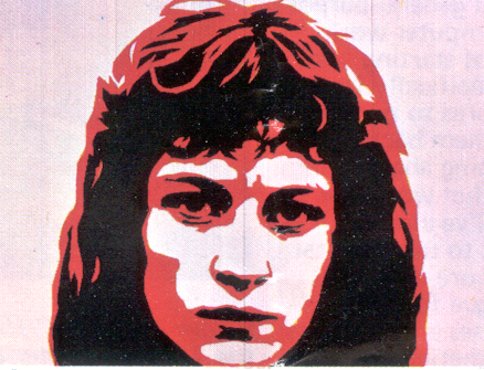
Now all we had to do was get the pictures moving. At this time in March - Colin Emmett had just designed a title sequence for the BBC-TV programme Burke Special, using high contrast photographs of James Burke. We decided to make this the first use of the scanning routine and Technicolor; however, since we were doing the animation on an IBM computer at Croydon instead of the Atlas computer, we had to simplify things a bit. Instead of using the full range of colour density, we just used the pure primary colours; and also to simplify things, we kept the three colour images quite separate, without registering them. The result is very similar to something produced by Scanimate; however there is one important thing that Scanimate cannot do. In the film we have pictures of James Burke's face taken from different angles, and we in-between automatically from one to another. Look carefully, and you will see that often these transformations do give very convincingly the effect of the head turning in three dimensions. [Film shown: BBC title sequence "Burke Special" ] While Colin was working this, I began work on the first fully animating version of the Antics program.
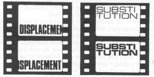
Animation movements can generally be divided into one of two categories. Displacement means any operation where a basic image is moved around under the camera, without actually being changed itself. Conventionally, displacements are usually done by the rostrum camera. This covers things like pan, tilt, zoom, spin, flipover and rollover - plus special effects like wobble glass.
The other category is substitution. This is where one image transforms gradually into a different image - conventionally this is done by substituting the image under the camera for another image that differs only slightly, and repeating this step by step in a systematic way until the required transformation is achieved. This, of course, is in-betweening. This is the really hard graft of animation - but it's also where the greatest freedom of expression lies.
We began with the very simplest displacement operations - pan, tilt and zoom. These were so simple, it's hardly worth mentioning. So we went straight on to the most difficult: transforming smoothly between completely unrelated images. This is a most powerful operation. It is important for character animation if you want to in-between from a side view to a front view, which may be completely different in the way they're drawn. If we could do that, of course, we would also be able to in-between from ANY image to ANY OTHER image. This we got working in March, at which time we happened to be making another film for the BFI, so we thought it would be appropriate to follow up our first computer effort by using the new transformation routine for an end title. The film ended with a photograph of the facade of the National Film Theatre, so we decided to transform this picture into the title lettering. We were only making the film in black and white, so unfortunately we didn't do the sequence in colour, but it came out like this. . . [film shown, NFT title sequence fig. 10a ]
By the end of March, we had all the features described so far combined into a single program. This was when ANTICS finally got christened (it stands, by the way, for Animated Technicolor Image Computer System). Since it was the third version of the program, we called it ANTICS-3. The animation capabilities were still fairly crude, but we did at last have a single working system. Moreover, it was quick and easy to use, gave quite acceptable results, and was also surprisingly cheap.
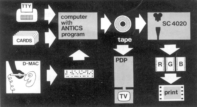
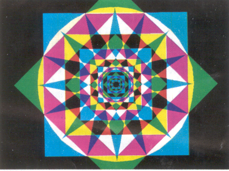
So now we can give a summary of the system (fig 11). First input to the system is the D-MAC pencil follower. Here you can trace your designs and produce a digitised version on paper-tape, which can be immediately fed into the computer's memory files and stored until needed. Then you feed in the details for composing the image. This is done either from a teletype keyboard, or else by punched cards. This will include specifications for colouring; but also at this stage you can, if you wish, specify a whole range of composition operations. These are the ability to repeat your basic design in many different positions and sizes. Figure C7 shows a design composed in this way from just two basic elements: a circle and a square. The manner of specifying these things is quite straight forward; basically it is like filling in a questionnaire - how many character sets?; how many figures?; what colour is each figure? and so on.
All that remains now is to feed in the animation data, and this is done in precisely the same way - via keyboard, or by punched card. To help in this we sometimes prepare a bar chart, though it is perhaps more like a cue sheet. You specify details of the animation required of each picture element by reference to a library of basic operations or functions. Animation functions can be applied both to complete character sets, and also to individual figures within the character set - this enables you for example, to have a character's arms and legs animating while at the same time he zooms off into the distance. The Antic program so far contains 20 available functions, and here is a run-through of 16 of them. . . [demonstration film shown] we have PAN (horizontal displacement), TILT (vertical displacement) ZOOM; FLIP and FLAP (perspective flipovers; see fig 12); SPIN WAVE and SHAKE (sine-wave distortions), WOBBLE (squash and stretch), TUMBLE and TURN (rollovers), REPEAT, PATH (moving along a freely-drawn curve), TWIST, SCALEX and SCALEY {linear stretching). Another function is simply a hold; two more are transformation routines, and the last is a skeleton animation routine.
To specify a particular function, all you have to do is provide numerical details according to a fixed format - again, like answering a questionnaire. For example, if you want a zoom on a particular picture element, you give first of all the frame which it is to start and the frame it is to end; within those frames you can then specify whether all these frames are to be taken up with movement, or whether you want holds at the start or end. Then you specify the percentage size it is to begin, and the percentage size it is to end, and the position of the vanishing point. Finally, you specify whether you want the movement to go completely uniformly, or whether you want it to be cushioned at start and end. Incidentally, the vanishing point need not be on the screen. The animation board can happily be regarded as extending almost indefinitely in all directions. There is no particular limit to the number of functions that can be applied; furthermore you can apply functions to functions. For example, instead of specifying a zoom hold of 100% (which would just give you a stationary picture at original size), you can specify a zoom hold with a CONTROL FUNCTION. This might be, for example, a sine-wave oscillating between 5% and 100% with a period of 48 frames. The net result would be that instead of a zoom hold, you would get your picture zooming back and forth between 5% and 100% of its original size, with a period of 48 frames.
The concept of control functions is very similar to the concept of voltage control used in electronic music synthesizers. Of course, the variety of possible combinations of functions and control functions is practically infinite - and we are continuing to add new ones all the time.
Anyway, before we look at some examples, let's complete our summary of the system. Having typed in the animation details, you are ready to go - this is done by typing in a command to run the Antics program with the data you have typed in; this generates a tape ready for plotting on the SC-4020. Before plotting, however, you can preview the images on the tape by use of the PDP-15 and its TV display. This allows you to view your animation frame-by-frame before committing it to film. Also, if you wish, you can ask the Antics program to omit the scanning process altogether, and just to generate the outlines. This gives you, in effect, a line test. This can be played back immediately on the PDP-15; furthermore, unless the images are very complicated, the PDP display will give you playback at almost live-action speed. If you then want to change anything, of course, it's simply a matter of typing in the corrections on a teletype terminal and running the program again. [Film shown - example of a line test plotted on 16mm film.]
Finally, when you're satisfied with the animation, you run the final full-colour version of the job; the tapes are handed over to the SC-4020 for plotting onto film; negative processing is done by the Atlas Laboratory itself, so that hopefully within 24 hours, your negatives are ready for Technicolor.
Antics-3 was the first fully-operational version of this system. The first job we gave it to do was to produce a title sequence for the Atlas Lab. This is a chart of the entire sequence (slide shown). The Atlas Lab picture was set number one; the various figures that make up this set were given various different pan, tilt, zoom and flip movements. Then we specified a transformation into set number two, which was the title lettering. Finally we specified a flip and a zoom on the lettering, making it turn and disappear into the distance. One thing to notice is the perspective rotation, of the building at the start of the sequence. Although our approach is basically 2-dimensional, the flip function is here used to give a very good perspective effect. Let's look at the result. . . (film shown: Atlas Laboratory title).
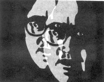
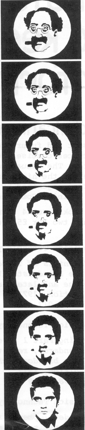
The transformation is interesting because it is completely uncontrolled - that is, we made no attempt to relate any particular part of the Atlas picture with any particular letter of the title - this correspondence was determined by the program. However, it is also possible to determine the correspondence yourself. Here's an example of a controlled transformation between Groucho Marx and Elvis Presley . . . (film shown: see fig 10b).
Next is an example of a transformation between a coloured contour map and just a few single points. The result could well be a scientific simulation of some changing potential energy process, and is a good indication of the kind of application Antics could have in educational work . . . (film shown: contour sequence).
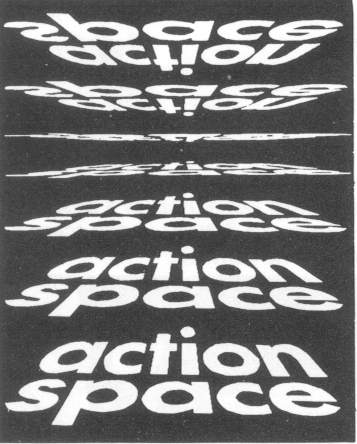
Here's a sequence that was specially made for Film 73. It's a transformation again, but the correspondence between the start title (BKSTS) and the end title (Film 73) was changed for each colour separation - so although both titles are white, it breaks up into a kaleidoscopic pattern of primary colours during the transformation. This sequence holds our record for quick animation - the whole thing took just half-an-hour to make, from feeding in the lettering designs to getting a tape onto the SC-4020. (Film shown. . . Film 73 title sequence).
So, as you can see, the transformation function alone has many possibilities. However, there are many points of interest in some of the simpler functions. For example, on a conventional rostrum, you are lucky if you can get a zoom ratio better than 20 to 1. If you want more than that, you either have to use the complicated and time consuming match-frame technique, or else produce a whole series of animated zoom drawings. Either way, it's not an easy job. The Antics program, however, will give you a zoom ratio of 10,000 to 1. I did a little arithmetic which shows that if you wanted a rostrum camera to zoom out from a 1 inch field to a 10,000 inch in field, the rostrum would have to be about 2,000 feet high, and the artwork would be nearly 300 yards across. Here's an example of a 3,000 to 1 zoom. . . (Film shown: Centre for Bio-energy logo zoom sequence).
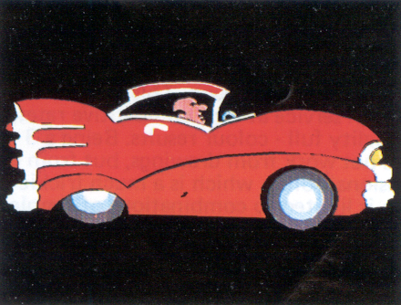
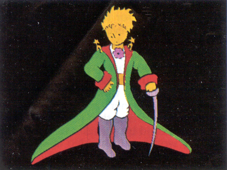
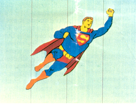
Tumble and Turn are interesting functions. Basically they represent the result of projecting the image onto a cylinder, and then rotating the cylinder. The motion is therefore governed by a sine-wave; lots of fun can be had by combining them in different ways. Here's the result when we applied two identical functions to Superman, but at right angles to each other. Then we did it again with one function going at double the frequency of the other. At the same time we applied a sine-wave controlled zoom to give the effect of him disappearing into the distance and coming back again (Film shown: Superman sequence see figure C8.).
Incidentally, it makes a difference which order you specify the functions. For example, combining a flip and a spin - the flip turns about a vertical axis. If this is followed by the spin, then the axis will spin, If the spin is specified first, the axis of the flip will remain vertical, Here's an illustration of the difference. . , (film shown: Flip and spin demonstration sequence).
Here's another example of the routine PATH. This allows the animator to draw a movement curve completely freely. Any path of movement you wish can be drawn and fed into the machine just like any of the design drawings. Having done so, you can then make any of your pictures follow the curve simply by specifying PATH. Freely-drawn curves can also be used as control functions - for controlling a zoom, for example, or the orientation of a spin - or for varying an in-between image back and forth between two extreme positions. This last could be used to produce lip-sync mouth animation, by varying between drawings with different mouth positions according to a curve drawn on the bar chart. Anyway, here's a bounce sequence using a bounce curve; at the same time we applied a zoom from the distance, and used the wobble function to give the squash effect on the bounce frames. . . (Film shown: bounce sequence).
Finally, here's a sequence that uses almost all the functions together. It was made as part of an educational film demonstrating the structure of the molecule of DNA, the self-reproducing genetic material in the nucleus of living cells. This photograph (slide shown) is an electron microscope picture of the actual molecule itself. In the final film we start with this picture, and dissolve into the computer sequence which begins with a drawing traced from this photograph, thus matching it quite accurately. Then we zoom in and examine the 3-dimensional spiral structure of the molecule, which eventually we unwind into a flat diagram. . . (Film shown: DNA sequence).
So, it should be clear by now that skillful use of all these functions can provide unlimited potential; we've only just begun to explore them. All these functions are incorporated in Antics-4. However, there is one important thing Antics-4 will not do. It will not allow one picture element to cover another - all the elements are transparent, so that if they cross each other, the colours will superimpose. Antics-5 solved this problem, and this came into operation in July. This offers you a choice of three things for each picture elements. The first is superimposition, such as Antics-4 provides (fig. 13). The second is hiding, which allows one picture element to cover another. And the third is elision, which allows two picture elements to merge with each other, provided they are the same colour. So, if we now want Superman against a sky background, it is a simple matter. The program automatically generates his silhouette, and then uses this to mask the background. Here is a simple sequence showing how easy it is to play around with relationships between background and figure. . . (film shown: Arrow and Ring Hiding sequence).
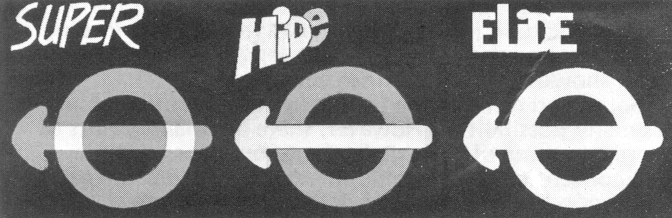
Each picture element is treated as occupying a single cel level. In conventional animation, you are usually limited to a maximum of five cel levels, because of slight light loss through each cel. Also, it is virtually impossible to make a picture element at one cel level merge with an element at another level. Here, however, there is no particular limit to the number of levels. The program presently allows 50 cel levels, but you could have more if you wanted. There is also no problem at merging at different levels. In the final part of the last sequence, the arrow went through the ring. This was done by having one half of the ring on the top level, the arrow on the middle level, and the other half of the ring on the bottom level.
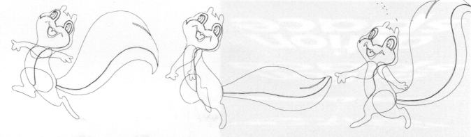
Finally, this brings us to the question of character animation. The facilities of Antics-5 are already enough to produce simple character animation, by using the in-betweening function. If the animator produces drawings of key positions in the movement the program will produce in-betweens, and the hiding routine will make sure that only the visible parts of each limb are drawn on the film. As a test we fed in 3 key drawings of Sylvester Squirrel (fig. 14), These drawings make up half of an animation cycle; we fed in some alternative arms and legs, from which a total cycle of 6 drawings was composed. We then used the in-betweening function to generate 18 more in-betweens, to produce a complete cycle of 24 drawings, and the result looks like this. . . (film shown: Sylvester Skipping sequence; see figures 15 and C9 ).
As animation goes, that's not too bad, but there are problems with this. The computer can produce in-betweens only by a mathematical process, which is very different from the way an animator produces in-betweens. The computer moves a character's limb from position A to position B, but it does so directly, without any reference to the overall shape of the whole movement. To get the computer to work out the shape of a complete movement just from three drawings would be no simple task. Without this ability, therefore, the animation often has a curiously mechanical quality, since it lacks a natural flow of movement. Of course, you could get over this by feeding in more key drawings - but if you were prepared to do this, there would be no point in using a computer at all, since the whole object is to be able to get the movement you want without having to produce dozens of drawings.
This brings us to the latest development, Antics-6. This is identical to Antics-5 except that it includes a new routine called SKELETON. The principle is this: any character drawing, however complex, is based on a simple skeleton structure. This illustration by Durer (slide shown) shows skeleton principle underlying classical forms of art. Traditional Disney-type animation is based on the same principle - start with a simple matchstick skeleton foundation, and then build the character around it. And this in essence is exactly what Antics-6 does. This means that instead of a number of key drawings, you simply feed in one basic drawing of your character, plus the corresponding skeleton. Then, to produce animation, you need only draw a series of skeletons, which only take a few moments to produce (fig. 16).
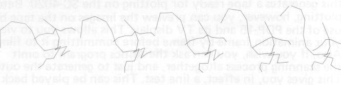
The program can in-between much more smoothly from one skeleton to another than it can with ordinary drawings, because it handles it as a network of hinged links rather than an arbitrary set of points. And since skeletons are so simple to draw, you can easily feed in a dozen of them for a single walk cycle, for example; this would be enough to give a completely natural shape to the movement, thus overcoming the problem of mechanical in-betweening. The program automatically fits each limb of the character design to its place on the skeleton; this operation also provides the ability to squash and stretch the limbs. If the length of a skeleton segment is changed from one skeleton to the next, the corresponding limb is stretched or squashed an equivalent amount. This avoids the result looking like a hinged cardboard cutout. The elide option enables different segments of a limb to be merged with each other; and finally, if you want to add further sophistication by having the head turning, for example, you can do this by feeding in an alternative head drawing and applying a cyclical transformation between the two. One more thing - having got a set of skeletons defining a walk cycle, for example, you can file it in your library, and use it over and over again for different characters. Of course, the skeleton principle can be applied not only to character drawings, but to any design that has a skeleton structure.
So, to finish off, a few words about the future. The system we have here is nothing more than a basic working prototype. It gives generally pretty acceptable quality results; it works quickly, taking probably less than £100's worth of computer time for an average 30-second sequence. There are still 2 major drawbacks, however, both due to the SC-4020.
This is the bottleneck in the whole operation. Complex sequences can take many hours to plot onto film. Also, inaccuracies in plotting often occur, and sometimes necessitate repeating the whole operation. And when you have got the negative, you still have to wait for a colour print. These snags could be overcome if we had one of the new generation of high-speed plotters, but these are very costly machines. Fortunately, there could be a much simpler way.
We are generating line-scan images with a definition and colouring comparable to broadcast TV. It would be a simple and fairly cheap engineering problem to convert the digital line-scan into an analogue one and store it on disc - the results could then be played back immediately on a colour TV monitor, and recorded direct onto videotape. One other advantage of this idea is that we would no longer have to restrict ourselves to a density range of 0 to 8, but could just as easily increase it to anything we like; this would allow us to achieve soft shading. In a sense, therefore, the ANTICS program is ideally suited to present video-recording techniques.
An even cheaper alternative would be to stay with film as a recording medium, but using one of the new precision TV displays instead of a microfilm recorder. These cost only a few thousand pounds, and models are now available that produce accurately registered images of a pure white colour, so that it would be possible to photograph directly from the screen through colour filters onto ordinary colour negative. This is the kind of device used in the Syntha Vision process, and gives perfect results for very little cost.
Another problem is computer access - at Atlas we are sharing a large computer with hundreds of other people on a first-come-first-served basis, which obviously limits the amount of work we can get done. Yet the Antics program could be run quite happily on a small computer like the PDP-15 - costing perhaps £30,000 to £40,000.
At the moment, therefore, we have a working animation system - but only just. The equipment we are using at Atlas was never designed to provide this kind of service, and so we are really pushing it to its limits. What is remarkable, however, is that the RIGHT equipment for Antics would actually be extremely cheap - comparable in fact to the cost of setting up a conventional animation studio. For most kinds of animation work, however, the running costs could be very much less - and the production time reduced to a fraction. So it certainly seems that a completely self-contained Antics studio is an immediate practical possibility -- and by cutting out the expensive and time-consuming labour of hand-drawn animation, it could be the starting point for entirely fresh experimental approaches to the medium.
