
Antics is a Fortran software package designed specifically to meet the needs of animators and graphic designers, with the following features:
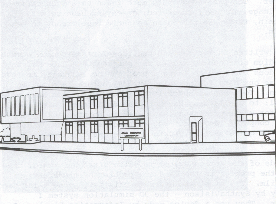
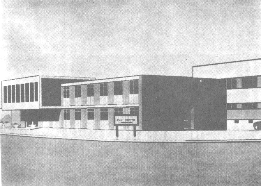
The system was designed in 1973 by Alan Kitching at Grove Park Studio, and is currently being implemented at the Atlas Computer Laboratory under the auspices of the Royal College of Art.
The appeal of animation as a medium lies in the fact that the artist has very great freedom to create whatever images the imagination desires. This freedom, in fact, is the main reason why animators are prepared to undertake the enormous labour involved. So unless the computer can get at least close to matching this freedom, the majority of film animators are not going to be whole-heartedly interested. Most computer graphics systems to date are not designed from the professional animator's point of view - they fail to meet some of the artist's most basic image-making requirements, and for this reason computer graphics has so far made little impact in the animation industry, in spite of its success in many other fields. Antics is an example of what I call a graphic animation system - a system designed specifically for animators.
To clarify this distinction, let us put Antics in its context by describing quickly the overall state of computer animation techniques. Roughly, we can divide computer animation into 3 categories: exploration, simulation, and graphic animation. All films have something of all three qualities, so these are not isolated categories; however, computer animation systems generally place major emphasis on one category.
The first, exploration, refers to the artistic exploration of filmmakers like John Whitney and Lillian Schwartz. Abstract work of this kind aims to explore the new artistic possibilities offered by the computer. Usually this involves exploiting the computer's mathematical precision in terms of geometrical patterns and textures. Because this kind of work is particularly suited to the computer, it's not surprising that most computer films to reach cinema screens have been of this kind; unfortunate, too, because many people have got the false assumption that computers can only produce abstract mathematical patterns. Artistic exploration is always a valid activity, but most film-makers are concerned with using animation as a means of communicating ideas and themes, and this involves exploiting and embellishing existing languages of visual design, not in inventing new ones. consequently, most animators regard abstract exploration as a highly-specialised branch of the medium; a future-oriented one, perhaps, with only occasional usefulness in present-day film-making.
Simulation is the bread-and-butter work of computer animation: a proven and valuable tool that allows scientists and engineers to study complex processes in revealing new ways. Most of the familiar computer graphics systems come under this heading; they are well-known to computer specialists, but because they are designed for scientific work rather than artistic work, these are of little interest to animators. The films produced are often nothing more than a convenient way of printing out the results of some enormous calculation; sometimes they are used for educational purposes, but even here that fact that every simulation has to have a special program written for it often precludes the possibility of employing professional graphics techniques for presentation. Only fortuitously do these films have great visual impact. The exception is systems that simulate the appearance of solid objects moving in perspective space. One such system is available as a commercial service to animators - SynthaVision in New York. This will produce realistic-looking full-colour animation of apparently solid objects - quickly and at competitive cost. The main drawback is that it is a 3D simulation system, and will therefore not accept 2-dimensional drawings. Everything has to be built up out of simple solid shapes spheres, cones, cubes, etc - with the result that it's tedious to work with, and everything produced tends to have a similar Toy Town quality. It would be more accurate to regard SynthaVision as computerised puppet animation.
This leaves the third category, graphic animation - here we deal with systems whose main aim is to provide a useful tool for designers and animators. This area is the most neglected, since the animation industry is not large enough to fund research, and people in other professions don't feel it's any of their business. Consequently, we find the only three systems currently achieving genuinely useful results have all originated in obscure corners, far removed from the world of big organisations. (Simple interactive systems like Ron Baecker's Genesys at MIT have too crude a picture quality to be of use to most film-makers.)
First and best known is Scanimate - operating in three studios in the USA, and one in London. As you may know, this is not strictly a computer in the ordinary sense, but an analogue video-manipulation device. It accepts artwork images fed in through a TV camera, and by manipulating knobs on a control panel this image can be made to distort, squeeze, bend, twist or whatever in a vast number of different ways. Because it is a video system, Scanimate can handle sophisticated full-colour images with instant real-time playback - something that digital computers cannot achieve at present. When the animator is satisfied with the playback, the sequence is finally transferred to videotape. The main disadvantage is that its animation capabilities are strictly limited - only five different colours can be used; it can't to full figure animation (except crudely), or moving backgrounds, or many other things that cel animation can do. A more sophisticated machine, called Caesar, has been built, but is not yet generally available. Scanimate has been very successful in the field of instant TV graphics, but it is otherwise too limited to be regarded as an all-purpose system.
Second is the system devised by the National Research Council of Canada, with the assistance of the internationally-known animator, Peter Foldes. Using an extremely small (16k) computer they have made a system more-or-less tailored to Peter Foldes' style of animation - he uses line drawings, with animation largely consisting of smooth transformations from one drawing to another. Using the NRC computer, he has made a film called La Faim (Hunger), which was the Canadian entry at the Cannes international festival. It is a savagely powerful film, and deserves special place as a milestone in computer animation - La Faim certainly can't be criticised as lacking passionate vision, nor of being inhumanly mechanical.
In designing Antics we have incorporated the animation principles of both Scanimate and of the NRC system; having more powerful equipment than NRC, however, we have been able to go some steps further. Our major limitations are that being a digital computer system Antics cannot operate in real-time like Scanimate, and there are also limitations of image complexity that I shall describe later. The design philosophy of Antics is best seen in relation to conventional animation. Conventional work embraces a wide spectrum from the very simplest techniques like cut-out animation, where whole films can be made quickly and cheaply, to the most beautifully executed masterpieces of the animation craftsman who enjoys the labour and devotion of frame-by-frame drawings. In between these extremes is a large area of film-making where traditional assembly-line techniques are used. Here there is a sharp distinction between the creative design work, and the work of producing the result. The distinction can be as sharp as it is between the architect who designs a house and the builder who builds it. Like the architect with his drawn plans and written specifications, the initial creative work of animation has two kinds of components; (a) drawings such as design drawings, character construction drawings, layouts, spacing guides and key drawings (b) specifications in the form of bar sheets or dope sheets. The rest of the work is purely mechanical. The specifications describe how the design drawings are to be combined, what in-betweening is required; they describe how they are to be coloured and photographed, and they describe what standard operations (like pan or zoom) are to be used. conventionally, this mechanical work is done by animation assistants, in-betweeners, tracers, painters and camera operators.
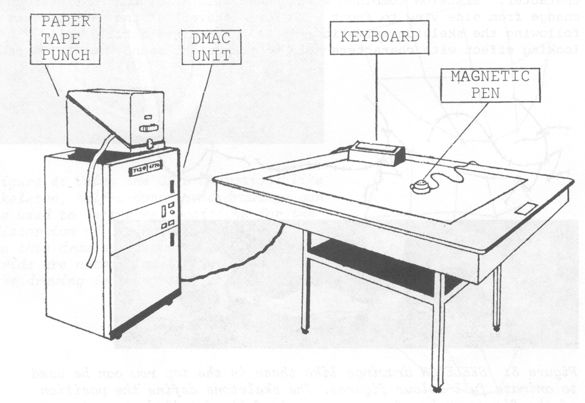
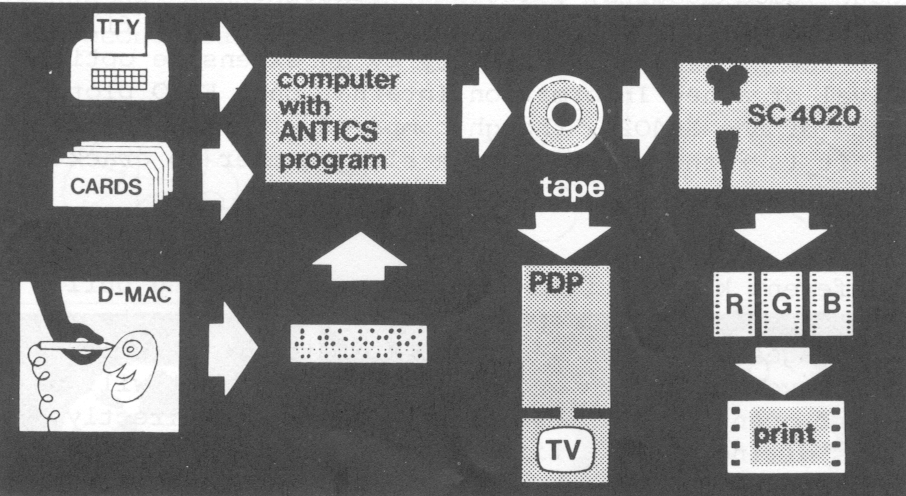
Essentially, Antics carries out all the mechanical work on the computer, while leaving the initial creative work as near as possible the same as in conventional animation. We begin, therefore, with drawings, which are fed into the computer using a digitising tablet such as the D-Mac pencil follower. This is like a large drawing table; you stick your drawing down and trace round it with a special kind of magnetic pen. The D-Mac senses the movements of the pen and automatically records the drawing. All drawings are fed in in the same way, whatever use we may wish to make of them. Besides using them as design images to be animated on the screen, they may be used as character construction skeletons; as grids to define how another image is to be distorted; as spacing guides to control the movement of another image; as backgrounds; as key drawings; or as graphs to control any other kind of change.
Once we have fed in the drawings, there now remains the specifications. These we chart out in a form resembling a cue sheet. Conventional animation charting deals with two things: a small vocabulary of key words like frame, field, pan, zoom, spin, fade, etc., plus some vital numbers - frame numbers, field sizes, start and end calibrations for a pan; in addition, drawings are numbered and assigned to numbered cel levels. Essentially, the Antics specifications are much the same, only the chart format is different.
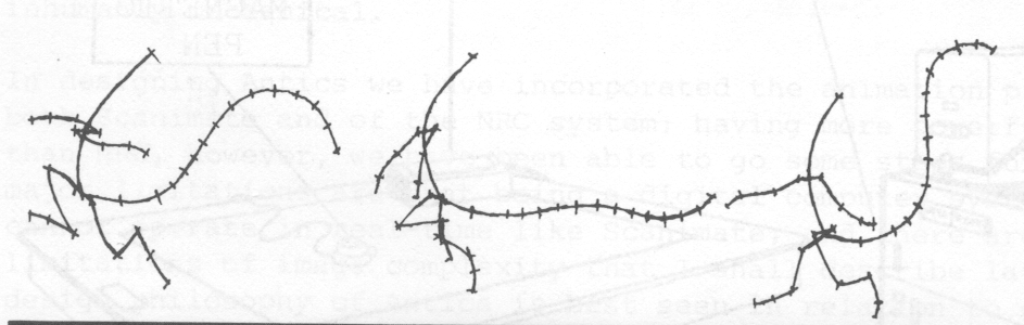
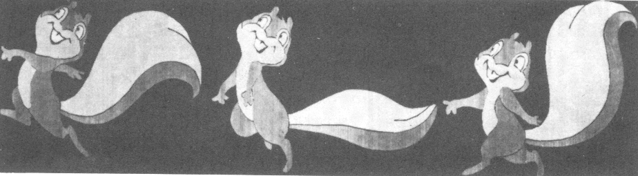
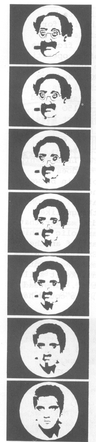
There are forty key words in the Antics system, each referring to one kind of animation operation. Some of them refer to basic displacement operations, mostly identical to camera movements: PAN, TILT, 200B, SPIN, HOLD, BANISH. Others perform distortions similar to Scanimate, or the effects of techniques like wobble-glass: WAVE, SHAKE, WOBBLE, EXPAND, GROW, WIG-WAG, BENDY, SPACE, SHIFT. Other operations are complete animation systems in themselves: CHN~GE will carry out smooth transformations from any image into any other, and on its own is able to produce animation like Peter Foldes' La Faim. SKELETON will carry out full-figure animation; it will take a few simple matchstick skeleton drawings as key-frames; it will in-between these; it will then fit a character of any complexity on the skeletons frame-by-frame to produce smooth character animation. Furthermore, skeletons used to animate one character can be stored and used again to animate another character. SKELETON combined with CHANGE will allow the character to change from side view to front view (or whatever) at the same time as following the skeleton animation, so we can achieve a fully solid-looking effect with characters able to turn right round.
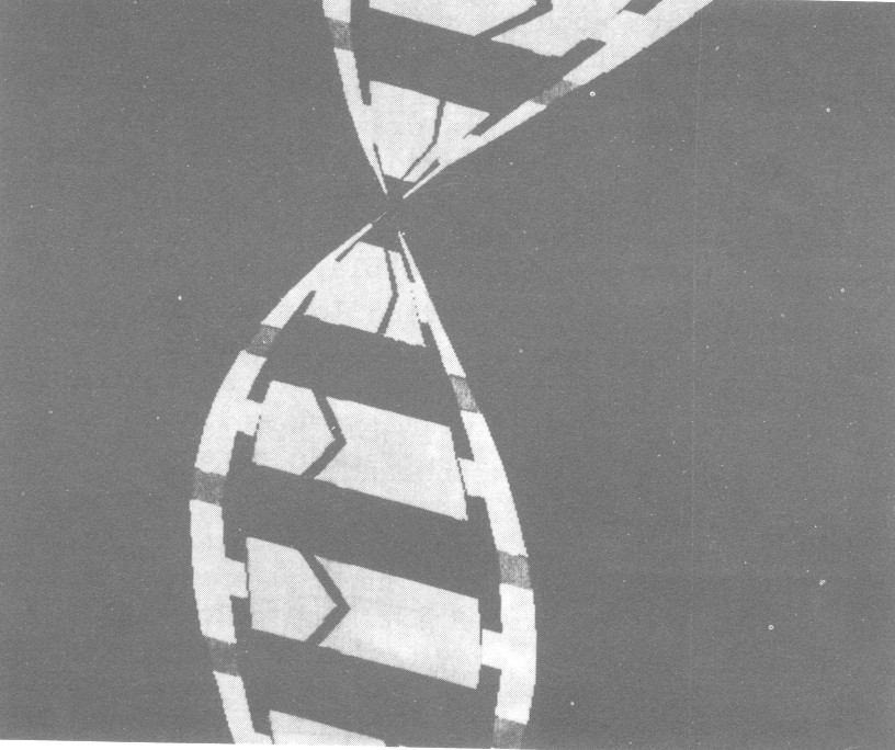
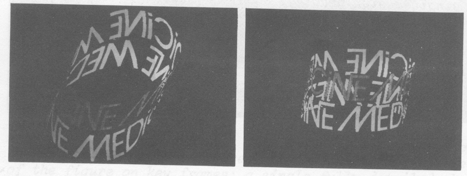
SKELETON can also use grid drawings to produce freely selective distortion effects, or to achieve apparent solid-effects such as a rotating globe of the world. FLIP and FLAP perform perspective rotations similar to the conventional flipover; TUMBLE and TURN perform perspective manoeuvres similar to a rollover. MASK is used to mask a drawing invisibly; SUPER allows complex matte effects to be achieved; MIRROR works like a mirror, and can be used to create kaleidoscopic effects; CYCLE is used to repeat sections of animation; PATH is used to make an image follow a freely-drawn movement curve; LEVELS is used to play about with the order of cel levels to achieve effects like having lots of images rotating round each other; FREAK introduces controlled random distortions into an image; CURLY will turn an image into an abstract geometrical pattern and play with it; TWIST will twist an image like a Christmas decoration and rotate it in apparent solid perspective.
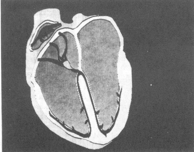

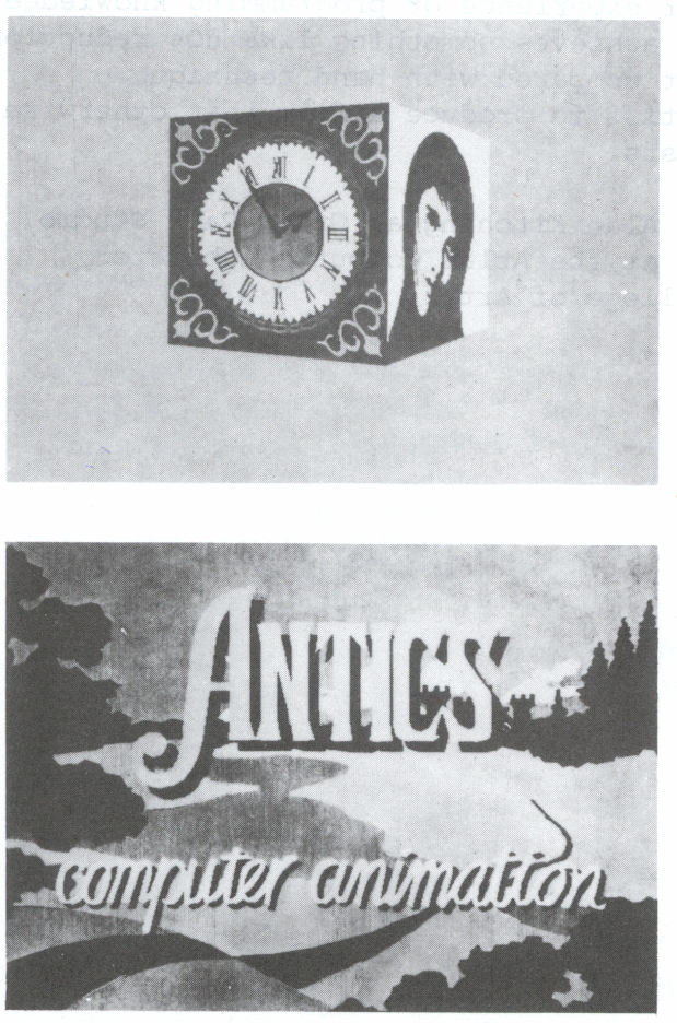
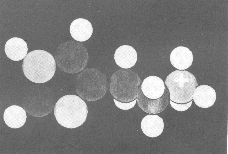
There is no particular limit to how many of these things you can have happening all at once. You can have up to 130 different picture elements on the screen at once, all doing different things. Even on their own, most of these operations can be used in a variety of different ways, and even the simple ones have a flexibility that is difficult to compare with the conventional equivalent. For example, on an animation camera you are lucky to get a zoom ratio better than 20:1; the Antics ZOOM will give a ratio of 10,000:1. FLIPS can be combined and controlled to give the effects of a rotating solid cube. TUMBLE can be used to take an image, curl it up into a solid-looking cylinder with perhaps different colours on inside and outside, and maybe perforated with holes - and then set the whole thing turning, finally to return it to its original flat state. Even the humble Pan can be used to take a complex image of a molecular structure and make it appear to rotate in 3-dimensions.
Incidentally, it is also possible to do 3D simulations directly. Unlike SynthaVision, Antics normally works with ordinary 2-dimensional drawings - this is important because artists usually think in terms of flat drawings, and if they want spatial effects, they know how to distort the flat image to create the illusion of perspective. However, Antics offers both worlds, because it is also possible to feed in a plan drawing and an elevation drawing of a solid object; if the two drawings are matched point-for-point, Antics will produce a 3D front-view perspective simulation. With suitable ingenuity, almost anything can be achieved.
However, this is only half of it. We command an operation to be performed by simply typing the numbers needed to describe it: for example, the start and end size of a zoom might be specified as 25 per cent and 150 per cent respectively. However, apart from the 30 operations listed above, there are a further group of 10 operations which are not applied directly to pictures, but only to numbers used in specifications; these 10 operations are called CONTROLS and are similar to the concept of voltage control in music synthesizers like the Moog. The SINE control generates a sine-wave of specified period and amplitude: for example, varying between 25 and 150 with a period of 50 frames. If we apply this control to the start size of the zoom, then the image will continually zoom back and forth between these two sizes. Controls can be applied to almost every aspect of every operation - even CHANGE in-betweening can be controlled in this way, for example. Other controls are: LINEAR which produces a linear change from one value to another; WEDGE does a change from one value to another and back again with holds in between; WANDER takes a freely-drawn curve as a. time-graph of the desired quantity, and is particularly useful for lip sync animation: RANDOM produces controlled random fluctuations for animating things like flames; TWEENY in-between things in a curiously spasmodic manner that has many unexpected uses; CURVE controls things in a parabolic fashion, like falling objects; TAG hitches an image onto some part of another image; TAPER produces various cushioning effects; PHASES allows things to pass smoothly from one state to another, then another, then another, and so on in indefinite controlled succession. You can take it still further. You can use a control to control another control. Instead of having the period or a SINE control fixed at 50 frames, you could have this period varying as well...
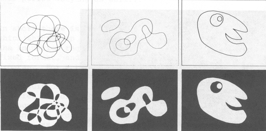
In short there is no end to the possible variety and flexibility with which things can be made to happen. Once we have prepared a chart of the animation required, we type in the specifications following a fixed format, and then give the command to run the Antics animation program. For a typical 30-second sequence of average complexity this will take about five minutes on the Atlas Lab's ICL 1906A computer. The result of this is a line-test, stored on magnetic tape, which we can view immediately on a TV screen. If we want to change anything, of course, this is simply done by correcting the specification and running the program again. If, like Peter Foldes, we wish line drawings as a final result, then the work is now complete, and may be plotted direct onto film using suitable hardware. However, if we want full colour results, we take our line test tape back to the 1906A computer and run a different Antics program - one that does the work of the conventional paint/trace department. This program takes the line test images, colouring in all the areas level by level. It also distinguishes between opaque colours and transparent colours, and if required can make a shape on one cel level merge invisibly (ELIDE) with a shape on another level; this allows shapes to penetrate and pass through each other. The program outputs each frame as a scanned image, TV image, in the form of red, green and blue colour separations. Again, these are stored on magnetic tape, ready to be plotted onto film.
The programs are written in Fortran and can therefore be run on almost any computer, medium size and upwards. The programs are data driven, so the animator does not need to learn a programming language; instead, we simply organise our data following a fixed structure laid out in the documentation. To computer specialists, the distinction here often seems quite small; to the layman, however, the difference is enormous. Most animators, for whatever reason, would refuse point blank to sit down and learn a computer language. Yet we have had artists with no computer experience quite happily picking up the Antics manual and actually completing a film in their first day.
The computing side of the Antics system is quite straightforward; the crucial part of the process is the hardware problem of transferring the results to film. The simplest answer to this is the one being used most successfully by SynthaVision - the 3D simulation system I mentioned earlier. They use a device made by Information Displays Inc. of New York: it consists simply of a precision black-and-white TV display, a movie camera with colour film, and a rotating red-green-blue filter disc; these are controlled automatically by a mini-computer from information on magnetic tape. The whole unit - tape deck, minicomputer, TV display, colour wheel and camera - costs about £20,000 (cheap by computer standards!) and gives thoroughly excellent results very economically.
At the Atlas Laboratory, where we have implemented the Antics system on an ICL 1906A computer, we have had to use a more elaborate method. Up till May 1975, all our results were plotted on an obsolete Datagraphix SD4020 microfilm recorder. This machine was never designed to cope with this kind of work, so we have had terrible problems coaxing it to produce good results; especially since we had to plot the red-green-blue separations on 3 different black-and-white films, and combine them in the processing laboratory by an expensive optical process. The arrival of a new Information International FR80 plotter overcomes the faults of the SD4020, though compared with the simple TV display device, it is rather like using a sledgehammer to crack a nut.
There is also a different kind of film-plotting machine being built at the Computer-Aided Design Centre in Cambridge. This converts the Antics scanned images into standard video format before recording on film. This will have all the advantages of the FR80, but will be much cheaper; it also opens up the possibility of working directly onto videotape, thus giving us real-time playback, like Scanimate. This brings us to consider some of the other possibilities for future Antics capabilities.
At present, we use key-frame matchstick skeletons to achieve full-figure character animation. However, we are currently investigating an even simpler possibility - the use of Benesh notation. This is the music-like notation that choreographers use to script dance movements, and my colleague, Colin Emmett, is currently writing a program to convert Benesh notation into Antics skeletons, so the notation could be used to create Antics figure animation.
The Atlas Lab has an optical scanning device, which could be used like a digital TV camera so that drawings - and ultimately even photographs - could be fed in directly. We have written a program for this, but not yet implemented it.
The animation program itself could be operated interactively on the Atlas Lab's PDPl5 computer, allowing movements to be controlled directly by touch, in the manner of Scanimate, though only in line test form.
Finally, there is one Antics facility that I haven't even mentioned yet. Besides drawing pictures, Antics also has a program that draws optical sound tracks. This in itself is quite a sophisticated thing. It operates in a manner almost identical to electronic synthesisers like the Moog or the VCS3, but with several important advantages. A synthesiser consists of a number of electronic gadgets that generate sounds such as sine waves, square waves, white noise, and such. In addition to these sources of sound, synthesisers also have various devices to modify sounds - filters, reverberation units, ring-modulators and envelope shapers. Complex inter-connections of selected gadgets can be discovered that will produce a vast variety of sounds - effects like wind, rain, storms, explosions, guns, squeaks, bells, drums, and fair imitations of most musical instruments, as well as musical sounds unlike any natural instrument.
In synthesiser terminology, a specific arrangement of devices (corresponding to a specific kind of sound) is known as a patch. The Antics sound track program works in the same way. An Antics patch consists of a specified arrangement of sources and treatments: the same devices are used in Antics as in a conventional synthesiser, so that it is possible to use a synthesiser to design a patch and then transfer it to Antics and get the same sound. Antics patches can be stored on punched cards and used over again; another advantage is this: on synthesisers the frequency of a note is set by turning a dial and it is not usually possible to set a second note to be exactly locked to a harmonic of another; in Antics patches this is possible, because frequencies can be specified as precise numbers, or as precise ratios of other frequencies. This allows complex sets of overtones and harmonics to be used. In the Antics program, you can have up to twenty different patches all producing different sounds simultaneously,' so this is equivalent to having twenty synthesisers at your command. To generate music, the Antics program will accept a musical score; this may have up to twenty tracks, each with its own melody and its own patch. Notes are written simply as A, B, C, CS for C sharp, and so on, plus the number of beats duration of the note, and a digit to identify which octave the note is in. Consequently, with a selection of patches giving sounds of different instruments, and a track of music for each patch, it's possible to create an entire band.
The Antics sound track program will also accept hand-drawn shapes and use them either as wave-forms, or an envelope for other sounds. In effect, this is an automated version of Norman McLaren's hand drawn sound tracks. The shapes produced on the sound track are often quite striking - our first musical test was Maxwell's Silver Hammer rendered in square waves; the resulting sound track included shapes that looked like little hammers. Of course, it's also possible to use the sound track shapes as picture - with different tracks in different colours - but this is something we've not yet had time to explore. The timing of sound tracks is measured in frames, which underlines the fact that the program is essentially intended as an accompaniment to the animation program, giving the animator the facilities of an electronic music studio, but able to produce sound tracks tightly synchronised to his animation. This brings us back to our starting point - the basic purpose of it all.

One of the commonest questions that arises with Antics is who will have access to use it. Surprisingly enough, the answer is that anyone who is a student (or staff member) of a university or polytechnic in Britain can apply for free use of it, as can people in government establishments. Consequently, it is far from being a luxury enjoyed only by the big media companies, and we'd certainly like to encourage any student with a creative experimental project to take advantage of this fact. This illustrates the point of it all - to allow one person, entirely on his own, to conceive and produce a film that otherwise would require a team of assistants to make.
In an existential sense, anyone engaged on a mechanical task has become, for the time being, a machine. As a society we are beginning to move away from situations where one individual performs mechanical tasks for the benefit of another. Animation has always been severely handicapped by the amount of mechanical labour involved. It would be difficult to estimate how many films have been abandoned at the ideas stage simply because of the labour and cost that would have been needed to make them it's also difficult to imagine what the animation industry would be like if everyone in it was directing their own films, rather than most people working on someone else's film. This indicates something of the untapped potential that exists for animation; if computer animation can release this potential it seems quite likely it would have a revolutionary impact on the whole area of visual communications.
