
The weather satellites are of great interest to meteorologists but there is also meteorological interest in the Anglo-American series of ARIEL satellites which carry instruments for making various scientific measurements. For example, ARIEL 2 (launched April 1964) carried equipment, designed by the Meteorological Office, to measure the vertical distribution of ozone up to heights of about 100 km. The Anglo-American co-operation in producing this series has taken various forms. The first two ARIEL satellites were constructed and tested in the United States though the scientific measuring equipment was built in the United Kingdom. ARIEL 3 however, launched on 5 May 1967 by the National Aeronautics and Space Administration (NASA) of the United States, was entirely constructed and tested in the United Kingdom.
ARIEL 3 carries equipment for five scientific experiments which were chosen by the British National Committee for Space Research from a number submitted to them by universities and Government scientific establishments. The main problems in choosing a group of experiments to be carried out on a satellite are first, that of eliminating any electrical interference between the experiments, and second, the choice of an orbit suitable for all the experiments.
The five experiments chosen were:
The first four experiments give a comprehensive picture of the state of the ionosphere especially as regards radio propagation. The Meteorological Office experiment was included because of interest in the composition and heating processes of the atmosphere at heights where dissociation of O2 is taking place. Previously, few such molecular oxygen distribution measurements had been made from sounding rockets [1] [2] and a satellite enables many more measurements to be made, well distributed over the earth and extending over a long period. In addition, all these measurements are made with the one piece of equipment.
When these five experiments had been chosen the choice of orbit remained and the greatest conflict here was between the experiment measuring galactic radio noise (Jodrell Bank), and that measuring terrestrial radio noise (RSRS). Normally galactic radio noise is absorbed by the ionosphere below about 500 km so that it cannot be received by a satellite orbiting below this height. Similarly, because of absorption by the ionosphere little terrestrial radio noise reaches above about 550 km and thus a compromise height of orbit was needed so that both experiments could receive a useful amount of signals through the lifetime of the satellite. In addition, the Birmingham University electron experiment was best suited to constant height (circular orbit), and the Meteorological Office required only a minimum height, so that the satellite was above any expected molecular oxygen. This minimum height is about 350 km and the accuracy of measurement of O2 is reduced at any height above this. The orbit chosen finally was a circular one of 550 km above the earth at an inclination of 80 degrees to the equatorial plane of the earth. This inclination ensures that the satellite passes over the auroral regions and also that the plane of the orbit precesses in space by several degrees per day to give the Meteorological Office experiment good coverage over the earth within a few weeks of launch.
Information from the five experiments may be received in 'real time' whenever the satellite is within range of one of the sixteen ground receiving stations. It may also be stored on a tape recorder within the satellite and played out on command from the ground as the satellite passes within range of a ground receiving station. The Meteorological Office experiment uses only the 'real time' system since this allows data to be transmitted at the high rate required by the experiment. The satellite is within range of a ground receiving station for between one quarter and one third of its orbit so that a great deal of information may be obtained using only the 'real time' system. (There are approximately fifteen orbits round the earth per day, each one with a satellite 'sunrise' and satellite 'sunset', when densities of O2 may be obtained.)
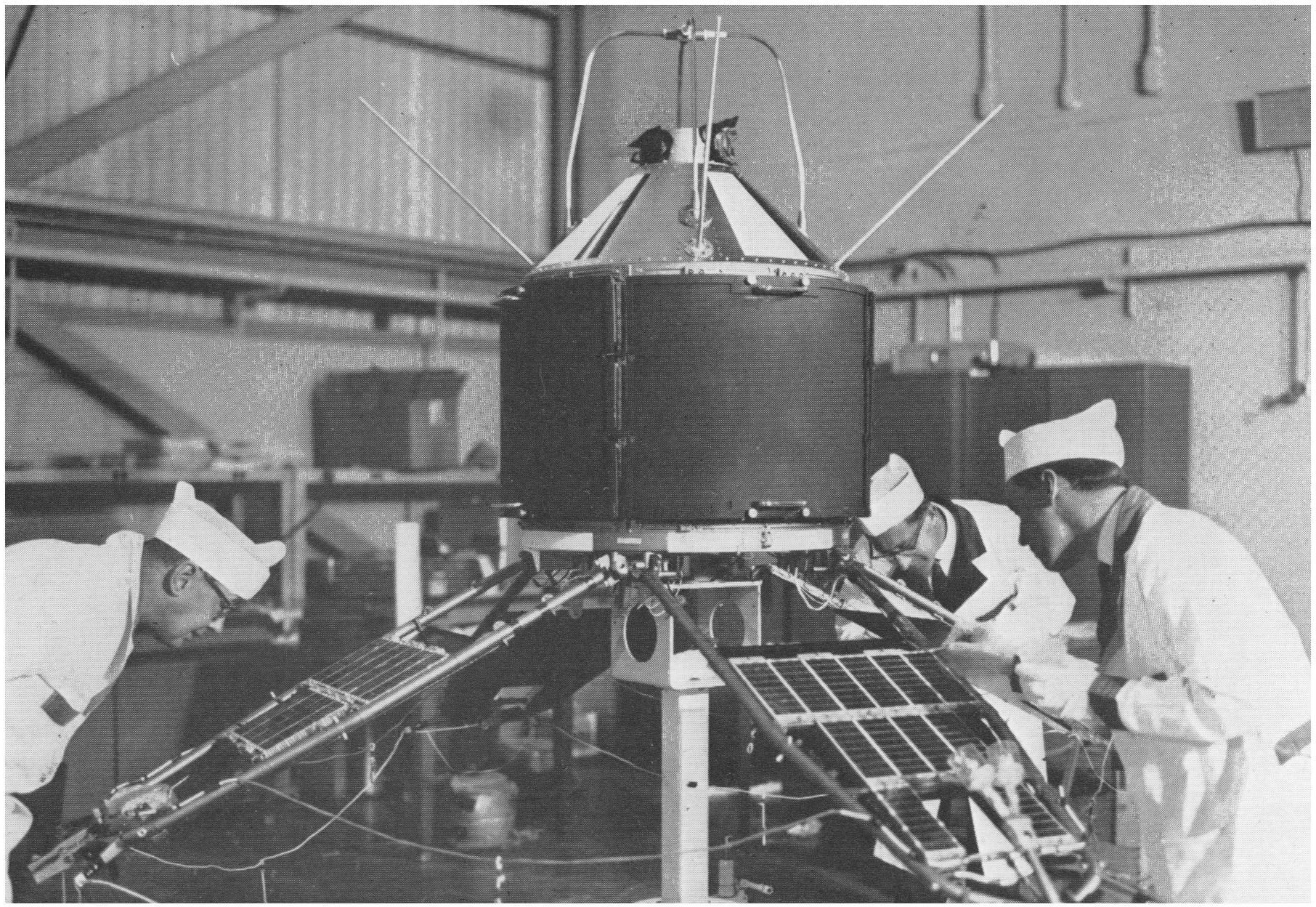
The main structure of the satellite was built by the British Aircraft Corporation (BAC) Guided Weapons Division at Stevenage, the power supply and telemetry equipment by the General Electric Company at Portsmouth, and the Royal Aircraft Establishment (RAE), Farnborough, was the overall design authority on behalf of the Ministry of Technology (formerly Ministry of Aviation). The equipment for the scientific experiments was provided by the experimenters themselves; some groups had this built by outside contractors, and some, such as the Meteorological Office, constructed it within their own establishments.
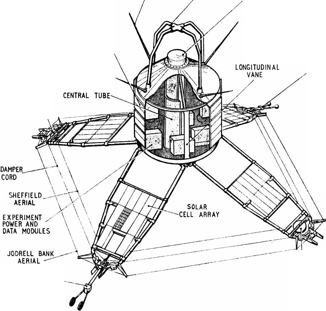
The basic layout of the satellite in its orbital configuration is shown in Figure 1. [3] The four booms are locked in their erected position and the cut-away section indicates the internal construction. Four equally-spaced longitudinal honeycomb vanes are fixed to the stiff centre tube, which provides the main rigidity of the structure. Most of the electronics of the satellite itself, and of the experiments, are fixed to these vanes. The solar cells which power all the satellite systems and experiments and which also recharge the battery for operation in the earth's shadow, are mounted on the booms and on the parallel surfaces of the main body. The Meteorological Office experiment is mounted on the conical top of the satellite to allow 360 degree field of view around the central spin axis of the satellite and a view 45 degrees above and below the equatorial plane of the satellite. The antennae of the Sheffield University and Jodrell Bank experiments are wound from tip to tip of the four booms, and the sensors of the Birmingham University experiment are mounted on the ends of two of these booms. The RSRS antenna is mounted on the top cone and causes no interference with the Meteorological Office experiment field of view.
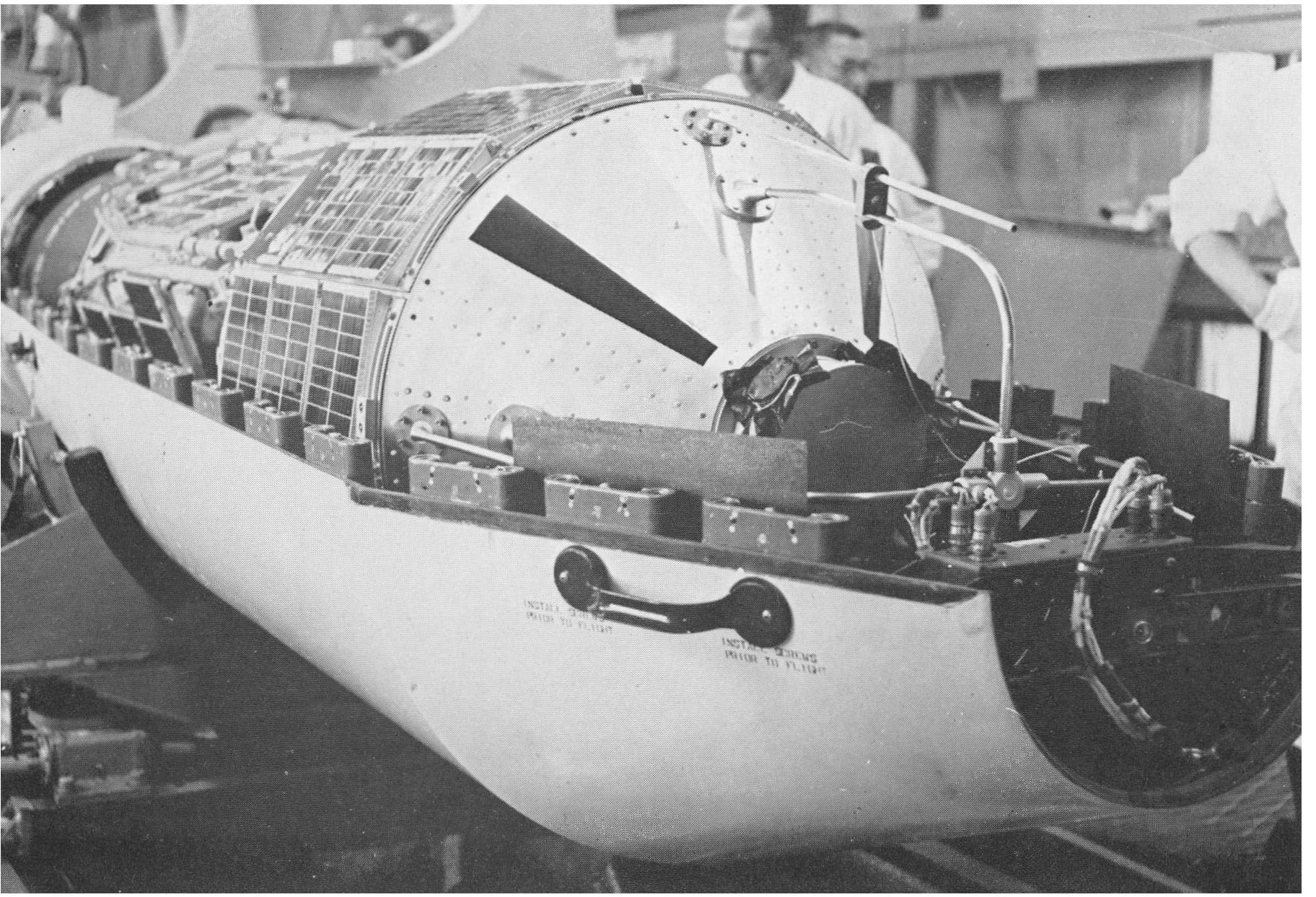
Once the overall shape and structure of the satellite had been decided it was essential to prove that the structure, including all its mechanical and electronic components, was able to withstand the vibrations and accelerations of launch as well as all the conditions existing during orbit. For this purpose five satellites were built, the first one being used for mechanical integration trials, and the second for electrical compatibility trials. The compatibility work on the second satellite lasted several months and consisted of adding each piece of equipment in turn to the satellite main structure. The object was to eliminate all sources of electrical interference between the various systems before adding any further items. This work was carried out in a specially constructed electrically screened room at BAC Stevenage, any interference found being eliminated or minimized by extra electrical screening, rerouting of electrical wiring between items, or by filtering introduced into the circuitry when possible. The third or 'prototype' satellite was completed embodying these modifications, and was then subjected to acceleration and vibration of severity 50 per cent greater than that expected at launch. After checking that all systems were still functioning satisfactorily, this 'prototype' satellite was placed in the 2.5-metre diameter 'thermal vacuum' chamber installed at RAE, Farnborough. In this chamber it is possible to apply light of solar intensity to the satellite under test in order to evaluate its thermal balance properties. It is also possible to heat and cool the satellite over a range of temperatures (-15°C to +60°C) to reproduce the temperatures the satellite is expected to attain in orbit. As a part of this testing, the complete satellite with all equipment installed and functioning was subjected to several days of solar simulation with light and dark periods corresponding to the satellite orbit. It also spent long periods at both high and low temperatures beyond the temperature limits expected in orbit.
The modifications arising from these trials were incorporated in the fourth and fifth satellites (known as 'flight' models). These two satellites were identical in every way and both were suitable for launching, the duplicate 'flight' satellite being an insurance against rocket failure, or the failure of the satellite in its early life in orbit. The 'flight' models were given low-level vibration and thermal vacuum tests, and individual experimenters were responsible for subjecting their flight experimental packages to low-level thermal vacuum and vibration testing before assembly of the satellites. The vibration testing of the Meteorological Office package was carried out at Atomic Weapons Research Establishment (AWRE), Aldermaston, whilst a small thermal vacuum facility was set up at Bracknell.
At heights about 100 km above the earth, molecular oxygen (O2) is dissociated by short-wave u.v. light from the sun. This effect increases with height so that at about 200 km the dissociation is almost complete, although some molecular oxygen is found at high levels. Little is known of the actual density of molecular oxygen at these heights or how it varies geographically and with time. Knowledge about this dissociation process is essential to our understanding of the physics of the atmosphere at these heights and of the possible effects of the dissociation process on the atmosphere at lower levels. In addition, the dissociation process at lower levels leads to the formation of ozone whose absorption of u.v. light of longer wavelengths is an important factor in the heat budget of the atmosphere down to as low as 20 km.
The principle used in the experiment is to observe the attenuation of u.v, light for a wavelength which is absorbed only by molecular oxygen. As the satellite enters or leaves the shadow of the earth it may be seen from Figure 2 that the 'grazing ray' from the sun to the satellite passes through the atmosphere. As the satellite moves, the ray passes through different height regions in the atmosphere and the intensity of u.v. light reaching the satellite depends on how much has been absorbed by molecular oxygen in the path. If (Imax ½)λ is the intensity of light of wavelength λ reaching the detector when no attenuation occurs, then when the 'grazing ray' is at height h the intensity will have fallen to (Ih)λ where:
(Ih)λ = (Imax)λ exp (-σλNh)
and σλ is the absorption cross section of O2 at wavelength λ and Nh is the total number of O2 molecules between the sun and the detector when the 'grazing ray' is at height h. By taking successive readings of the intensity of the chosen wavelength the density of molecular oxygen at various heights can be calculated. The path of the satellite varies with time and therefore observations can be made at different latitudes around the earth.
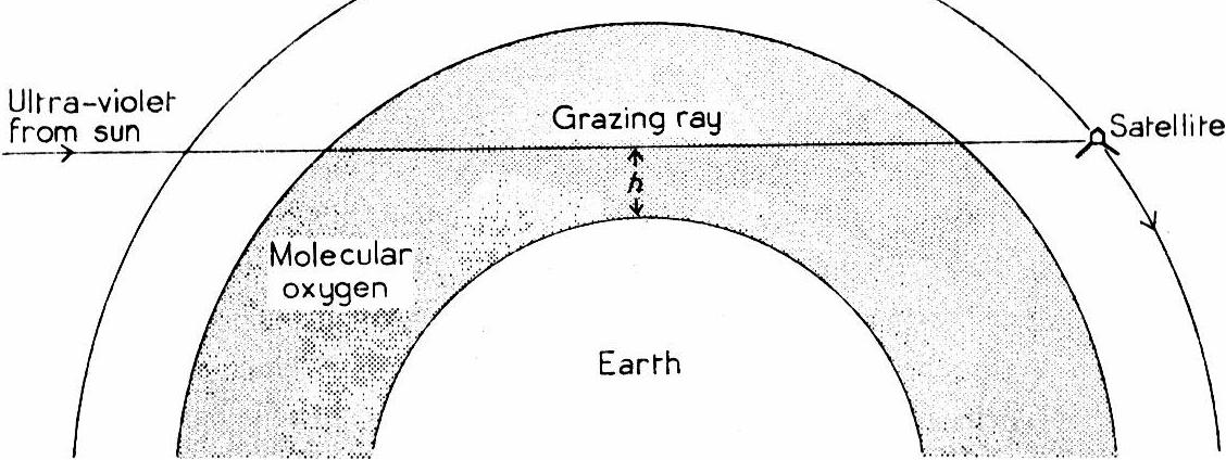
On the diagram, 500-600h indicates the height of the satellite's orbit in kilometres.
The maximum absorption cross-section of molecular oxygen occurs at 1450 Å and has a value of 1.48 × 10⁻¹⁷ cm2.[2] [4] If we observe the attenuation at 1450 Å we will be able to detect the smallest possible quantity of O2. It is essential to use a detector which has a narrow band response to u.v. light so that ideally we can consider monochromatic light, and the detectors used in this experiment are ionization chambers. In these, the lower wavelength of the pass-band is set at 1425 Å by artificial-sapphire windows, and the upper limit is set at 1490 Å by the ionization wavelength of the Para-Xylene (C4H4(NH2)2) gas filling. Light between these two wavelengths causes ionization of the Para-Xylene within the chamber, and the charge thus produced gives a measure of the light intensity.
Four of these chambers are mounted 90 degrees apart in the Meteorological Office apparatus and each of them points in turn at the sun as the satellite rotates at 30 rev/min about the central spin axis. The four chambers are connected as a single d.c. amplifier and it is the output of this which is telemetered directly to the ground stations. Baffles are placed over three of the ionization chambers thus eliminating reflections from the satellite body and restricting the field of view of each to a cone (of 45 degrees half-angle) so that only one chamber sees the sun at a time. These baffles also contain a gauze to allow for the variations between individual ionization chambers and also to reduce the overall u.v. flux. The field of view of the fourth chamber was specially restricted as described later.
Practical difficulties arose concerning the sensitivity of these ionization chambers to wavelengths outside the theoretical pass-band, and particularly in the wavelength region around 2000 Å. Here the sun is much more intense than in the 1450 Å region and in addition is not attenuated by molecular oxygen, so that it can produce a large, unwanted, steady signal which takes up valuable telemetry range. This signal could be ignored or 'backed off' within the circuitry of the instrument if its magnitude could be forecast accurately before launch. However, the absolute intensity of the sun's u.v. radiation is not known with sufficient accuracy to avoid waste in the use of the satellite's telemetry system. In this system the output range of the experiment from 0 to +5 volts is expressed in terms of 100 discrete 'filter' numbers, which are reconverted to experiment output voltages in the data reduction process. To overcome this uncertainty in the intensity of the sun's u.v. radiation, an ionization chamber, similar to those to be used in the satellite experiment, was flown in a SKYLARK sounding rocket which was launched at the Woomera Rocket Range, South Australia. This ionization chamber was calibrated on the same laboratory system as the satellite chambers, to reduce systematic errors. In addition, the actual chambers flown in ARIEL 3 were selected for minimum response when placed in u.v. radiation with approximately solar intensity for wavelengths longer than about 1900 Å. Actual calibration was not possible because of the very low quantum efficiency of the ionization chambers at 1900 Å though the efficiency was still high enough to give troublesome signals from solar intensities. The most likely cause of this sensitivity was thought to be photo-emission from the conducting walls of the chambers.
Launched early in March 1967, the rocket reached a height of 206 km, and showed that at this height the sun's u.v. radiation in the 1425 Å to 1490 Å band was much less than the published figures indicated. The launch took place at about 1500 hours local time so that the ionization chamber viewed the sun almost vertically through any O2 that remained above it, and it was estimated that the signal attained at apogee was within 1 per cent of the true 'full sun signal'. This result of low solar intensity led to gauzes of higher transmission being placed over three of the four ionization chambers in the experiment thereby making use of the full range of the satellite telemetry system. In front of the fourth ionization chamber there was placed a narrow slit which greatly restricted the field of view of the chamber. This was to prolong the lifetime of the chamber, since it had been found in the laboratory that prolonged exposure of this type of chamber to u.v. radiation of solar intensity at wavelengths longer than approximately 1900 Å, caused a permanent loss of sensitivity probably by destruction of the gas filling. The slit reduced the u.v. flux to one-third of the full value so that the estimated life of the detector was about three months, and data of reduced accuracy should be obtained for this period. It was estimated that the useful life of the other three ionization chambers with their larger field of view would be about one month in orbit.
The satellite was successfully launched at the first attempt by a NASA four-stage SCOUT rocket, on 5 May 1967, from Vandenberg Air Force Base, between Los Angeles and San Francisco, California. An elliptical orbit between 500 km and 600 km was attained, and the booms and equipment mounted on them all deployed correctly. The time of launch, 1630 GMT, was chosen to allow the Meteorological Office to obtain data for a number of days before the plane of the satellite orbit precessed to a position perpendicular to the earth-sun line. In this 'all sun' condition the Meteorological Office experiment obtains no useful results since the satellite never enters the earth's shadow, and in addition the rate of decay of ionization chamber sensitivity slightly increases. With this orbit, at 80 degrees inclination, 'all sun' periods occur about every 55 days and last about 18 days. The launch at 1630 GMT allowed seven days of Meteorological Office results before the 'all sun' condition and also meant that the RSRS terrestrial radio noise experiment passes over equatorial regions at afternoon local time, when thunderstorm activity reaches its peak.
The initial signals from the Meteorological Office experiment indicate 'full sun signals' at very close to the expected levels, and in the first month's operation of the satellite the sensitivity of the three wide-angle ionization chambers has fallen to about one-third of its initial value. The fourth ionization chamber has lost its sensitivity more slowly, and it is hoped that useful results will be obtained from it after the end of the first 'all sun' period. During the first seven days operation, oxygen density profiles should be derived over a wide range of latitudes in the southern hemisphere for satellite 'sunsets', and in the northern hemisphere for satellite 'sunrises'.
Data are being received from 12 tracking stations of the NASA Satellite Tracking and Date Acquisition Network (STADAN) which has stations throughout the world, and also by the 3 stations run by the Radio and Space Research Station, one at Winkfield near Bracknell, one at Singapore, and one in the Falkland Islands. An additional station, operated on a non-routine basis by Stanford University, is at Byrd Station in the Antarctic. This station received many satellite 'sunsets' in the first few days after launch but these results will not be received until the supply ship returns from Antarctica sometime late in 1967.
The data tapes from all these 16 stations eventually reach the Radio and Space Research Station for preliminary sorting and processing. After this, the data are passed to AWRE, Aldermaston, to make separate data-tapes for each experiment in a form suited to the processing requirements of the experimenters concerned. The Meteorological Office will carry out the final analysis of the data for their experiment on the computer at Bracknell.
JURSA, A. S., NAKAMURA, M. and TANAKA, V.; Molecular oxygen distribution in the upper atmosphere. Jnl geophys. Res., Baltimore, 68, 1963, p. 6145.
SMITH, L. O. and WEEKS, L.; Molecular oxygen densities from rocket measurements of Lyman -α absorption profiles. NASA Contract. Rep., Washington, 392, 1966.
CAMPBELL, F. P.; Orbiting a high atmosphere experiment. Weather, London, 21, 1966, p. 422.
BLAKE, A. J., CARVER, J. H. and HADDAD, O. N.; Photo-absorption cross sections of molecular oxygen between 1250 Å and 2350 Å. Jnl quantve Spectros. and radiat. Transf., Oxford, 6, 1966, p. 451.
