
The Engineering Board programme at RAL continues to be dominated by support for the work of the Information Technology (IT) Directorate. A large component of the IT programme is associated with the national advanced information technology programme coordinated and managed by the Alvey Directorate. The Alvey activities include supporting and managing its computing network infrastructure and organising and coordinating its research programmes in software engineering, expert systems and man-machine interface. In addition, the Laboratory has had significant involvement in the Alvey research activities, particularly in microelectronics.
The original components of the Computing Facilities Committee programme have been merged to become the Engineering Computing Facility. An Executive manages the programme which is concerned with the provision and support of computing for all Engineering Board funded users. The main emphasis is to re-orientate the work to be more application driven. In close connection with this programme is the new Department of Trade and Industry/SERC Transputer Initiative which is managed by RAL.
RAL continues to play a significant role providing services to academic designers of microelectronic devices through its computer-aided design, electron beam lithography and silicon brokerage facilities. Preparations are well advanced to set up at RAL a National Electronics Research Initiative in advanced electron beam lithography in collaboration with industry.
The Laboratory has continued to support UK radio communications through the National Radio Propagation Programme.
Early in 1987, SERC and the Department of Trade and Industry (DTl) launched a coordinated programme on the Engineering Applications of Transputers. The INMOS transputer is the first effective microprocessor on the market designed to work in a parallel processing environment. The primary aim of the Initiative is to capitalise on UK strength in parallel processing research by the transfer of this expertise into UK industry. A Working Party of the Computing Facilities Committee (CFC) made a number of recommendations in October 1986 which form the basis of the programme. A small coordination team at RAL has spent 1987 getting the Initiative started.
The main elements of the programme are to:
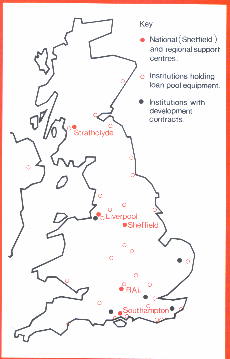
and progress has been substantial in each area (Fig 2.1).
The Transputer Loan Pool consists of a range of equipment mainly from the two major suppliers, INMOS and Meiko, and came into operation in May 1987. In the first few months, over 70 applications for loans were received of which 48 were approved initially to 33 universities and polytechnics in a variety of departments not all in engineering disciplines. Loans are for a four-month period and are intended to help researchers develop research grant applications.
The most common loan is for a basic development system consisting of a single transputer and an IBM-compatible PC allowing programs to be developed for running in a multi-transputer network. In the future it will be necessary to loan more substantial configurations as community expertise develops. A second set of loans was made in November 1987 and the pool is reaching a steady state with equipment returning and new loans being made on a monthly basis.
The UK has been divided into regions with a centre in each. One centre has been designated the National Centre with the role of transforming developments at other centres into products.
There were 23 bids for centre status and those chosen were:
| Centre | Location | Director |
|---|---|---|
| National and North-East Region | Sheffield University and Polytechnic (Joint) | Prof D Lewin |
| Scottish | Strathclyde | Prof J Durrant |
| North-West | Liverpool | Prof W Eccleston |
| South, South-West and Wales | Southampton | Prof A J G Hey |
| South-East and Midlands | RAL | Dr C P Wadsworth |
Contracts have been placed for short studies to determine what is needed to enhance currently available software. Southampton University is producing a User Guide to OCCAM and transputers together with software aids to allow existing programs to be easily modified to farm out work to a set of transputers (known as a processor farm). Brunel University is investigating the feasibility of a FORTRAN compiler which automatically recognises parallelism in a program and specifies the relevant transputer environment. A GKS OCCAM binding and a GKS implementation in OCCAM is being carried out at the University of East Anglia. At the application level, Liverpool University is developing finite element software and evaluating suitable algorithms for multitransputer arrays.
To publicise the Initiative, a regular mailshot has been launched. Demonstrations have been presented to both Council and Board, including civil engineering design software produced as a result of a loan. A major event was the Techmart Exhibition at the National Exhibition Centre where the SERC Transputer Exhibit was well attended.
Intelligent Knowledge-Based Systems (IKBS) is a major area of the Alvey programme in which SERC has had special responsibilities, including the provision of the Alvey Director. One of the Alvey Community Clubs within IKBS is ALFEX, which is concerned with financial expert systems. The financial sector is an important part of the UK economy and expert systems are seen as a competitive tool in this area. The Club consists of a consortium of UK companies and it developed two related expert systems in the domain of corporate finance. One is a Source of Finance Advisor, which assesses the most suitable means of raising money for a company with certain needs, and the second is a market assessor to determine the health and future prospects of a high-technology retail company.
RAL has amongst its interests knowledge representation and architectures for expert systems. It has been shown that in 'first generation' expert systems, the way that the knowledge is used tends to be 'wired-in' and therefore unavailable for examination and modification. In particular, the quality of explanations provided by the system of its line of reasoning and conclusions is often poor; in high-risk areas, good quality explanations are vital to a the acceptability of a system. One of the trends in second generation expert systems is to make the reasoning procedure more explicit and also abstract, ie separated from the domain knowledge. There is often a closer adherence to human problem solving methods and the quality of explanation improves because the reasoning, being more abstract, is not buried in a mass of individual expert rules.
The PARALFEX research project at RAL which is concerned with these issues is linked to ALFEX in that it has access to the expert systems developed for the Club and the transcripts of the knowledge elicitation sessions with the experts. The first development has been a re-implementation of the Source of Finance Advisor with a graphical explanation system. The presentation of results to the user is not something which can be left until the very end of development but must be considered at the outset. The design chosen is versatile and will be re-usable within future developments of the underlying architecture. A graphical approach was selected because of the limitations involved in the use of 'canned' text to provide explanations, which can often be inappropriate.
Fig 2.2 shows a typical screen during a consultation with the Source of Finance Advisor. The six finance options are represented by desirability meters at the left of the main screen. The black regions indicate that the desirability of the option is unknown: they shrink to single points as the consultation progresses. It can be seen that the options of debt factoring, equity finance and overdraft have all been eliminated (they have desirabilities of zero), medium term finance has been completely investigated and has a desirability of about 0.8, the desirability of sale and leaseback is so far completely unknown while venture capital is not fully investigated but has a desirability of less than 0.5. The user, seeking an explanation of why overdraft has been eliminated, has requested a display of its contributing factors. All the conditions shown in the second rank of meters have to hold for an overdraft to be viable. It can be seen that, in this case, the term of the overdraft is too long. Investigating further, the user has the relationship between the term and overdraft possibility displayed in the top right hand window. In general, the network of contributing factors may be displayed under user control to show in an immediately understandable form why conclusions are reached. This is particularly useful for what if? questioning and for assisting in the knowledge acquisition process as, in both cases, immediate visualisation and feedback is very valuable.

The system has been developed on a Symbolics 3670 using the AI toolkit Inference ART. A series of demonstrations to financial experts has confirmed that the system is much more comprehensible than those developed with conventional expert systems shells with their limited explanation facilities. Attention on the PARALFEX project has now turned to two other topics: the representation of experts' strategic knowledge, and the possibilities for re-using knowledge in different applications. The control knowledge which guides an expert's thinking during a consultation is generally not available to the expert system attempting to emulate it. To make it explicit would further enhance explanations and performance. System development and maintenance would be eased by having re-usable packages of knowledge available; in the financial domain, a good example is a package of knowledge about a company balance sheet and profit and loss account.
RAL has a long history of involvement with high powered single user workstations. Perq and Sun workstations have been purchased by SERC in substantial quantities. In addition, Whitechapel, Apollo, IBM and Silicon Graphics workstations have been used in specific areas. For the Engineering Board programme and Alvey, there has been a need to assess new workstations and to harmonise software on those acquired. A major problem has been the lack of standardisation of interfaces between workstations and applications and a number of developments have taken place to make software portable.
The WW Toolkit was initiated about three years ago to provide a portable library for developing highly interactive applications. Existing window management systems vary markedly in user and application programmer interfaces and in functionality. WW provides tools which fit on top of a window management system to isolate programmers from these vagaries as far as possible. Tools include window management functions such as opening windows, copying parts of windows, and defining cursors. Graphics functions such as drawing lines, mouse input with standard interpretations of the buttons and fill area are also provided. Support for pop-up menus is rationalised.
The Toolkit shields the user from the eccentricities of a particular system. For example, by defining a specific button on a mouse to activate pop-up menus, a house-style can be introduced across a range of workstations. Buffering picture updates and providing efficient fill area functions (independent of pixel to computer word mapping) ensure interaction quality independent of system representations.
WW has been used in applications at RAL and elsewhere. Software items are provided in source code form to act as exemplars for other applications developers. Experience gained with the SPY screen editor, an earlier RAL development, has been used to provide an even richer-functionality screen editor which is WW-based and hence much more portable.
The work needed to port WW to a new window management system is extensive owing to the different ways in which similar functionality is implemented. To harmonise window management systems from different vendors, UK suppliers have collaborated with RAL in defining a Client Server Interface (CSI) which provides a lower level interface than WW and which the vendor window manager should support. A specification of CSI has been developed and widely circulated as a contribution to standards activities in this area. A comparison between CSI and the new X-II interface has also been made available.
To demonstrate the viability of CSI, it has been implemented on a Perq and another workstation. WW has been rewritten in terms of CSI so that WW can be quickly made available on any window management system supporting CSI.
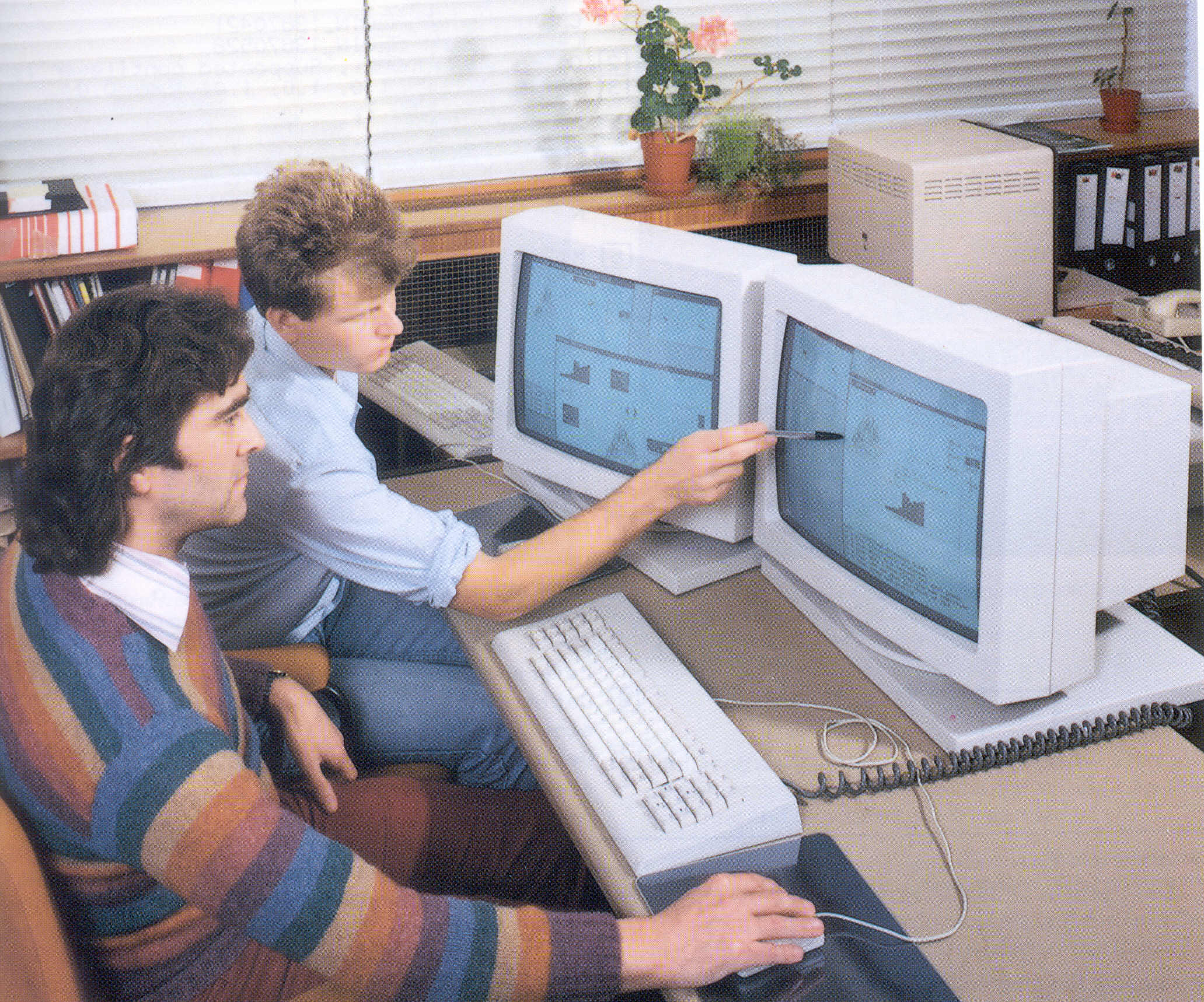
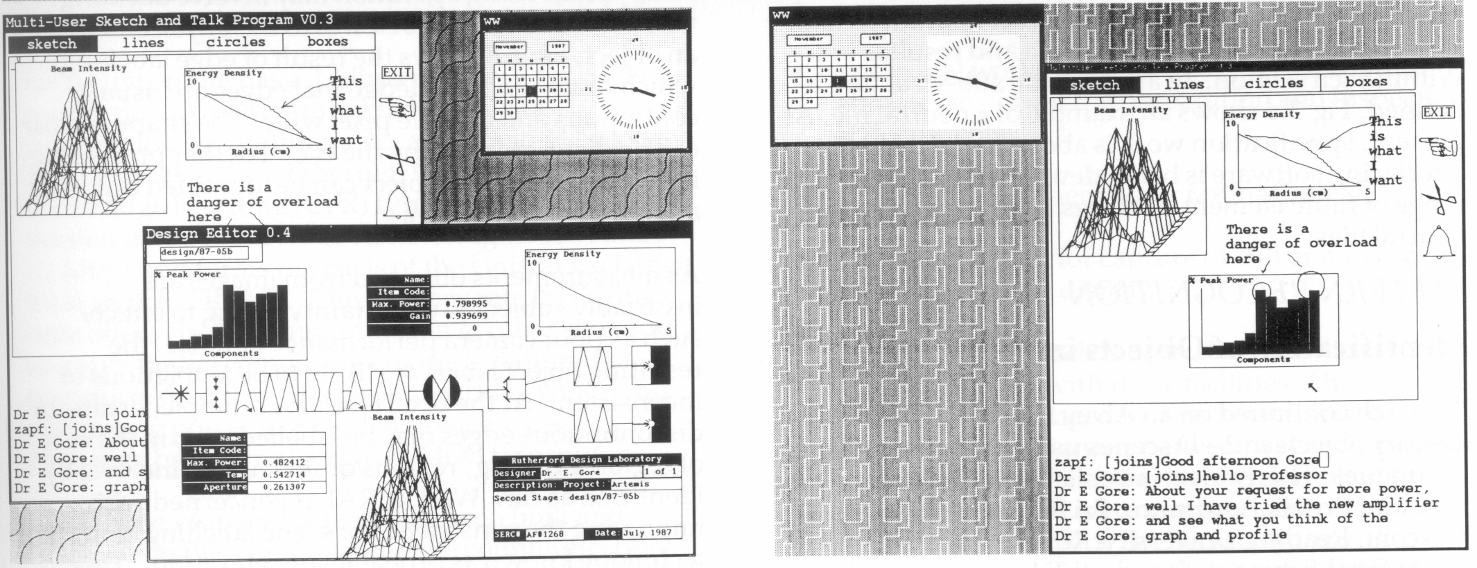
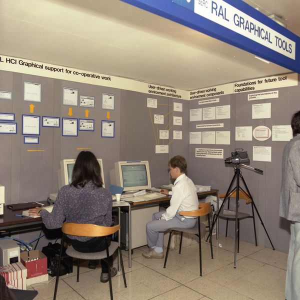
At the 1987 Alvey Conference, the use of high-powered workstations in cooperative design was demonstrated. A researcher and technician at different locations were shown using workstations connected by high speed communications to design a complex laser facility. Two separate utilities were written using WW to support the design environment. One of these is MUSK, a Multi-User Sketchpad (Fig 2.3), which enables mixed text and graphics to be generated by a number of workers using a single common drawing area. The other utility, PIXVIEW, is essentially a software video camera. It enables one worker to see part or all of the screen of another (with permission). Thus, one worker can, for example, see a complex simulation running which he may not be able to run on his own machine. The demonstration showed the sophistication of user interfaces which can be developed quickly using toolkits developed at RAL.
Computer-Aided Design systems now and in the past have tended to consist of a set of modules or packages designed to solve specific tasks. Frequently, the individual parts have been developed independently. Consequently, the transfer of results from one module to become input to another may not be straightforward. The first attempt at providing an interchange standard was IGES (Initial Graphics Exchange Specification) developed by the National Bureau of Standards. It was originally targeted at data exchange between databases of computer-based drafting systems and concentrated on line drawings and product data in the area of geometric modelling. The most commonly used IGES is Version 2 which was published in 1983. Since then, other exchange formats have appeared. The International Standards Organisation is attempting to create a single international Standard for the Exchange of Product Model Data (STEP).
CAD*I is an EEC ESPRIT project begun in 1984 with the goal of developing interfaces between different CAD systems and between CAD systems and finite element systems. The aim is to allow easy transfer of product definition data for mechanical parts between CAD systems, the transfer of this data into analysis systems, and the transfer of analysis models and results between analysis systems. There are 12 partners to the project from 6 member countries. RAL involvement is with finite element aspects of the project with the aim of providing interfaces to permit transfer of models and results between systems. Links between CAD*I and STEP ensure compatibility and allow experience gained in CAD*I to influence STEP design.
The major development has been the concept of a neutral file as a means of transferring information between systems. This neutral file has to be sufficiently flexible that it can cater for a range of CAD and finite element systems. It might include all the data necessary to perform an analysis on a product together with the results of the analysis. For example, a CAD system might specify the geometry of the product and pass it to a finite element preprocessor which defines the mesh to be used by breaking the complete object into a set of elements. Material and physical properties need to be added to the data before a finite element analysis program is called. The complete set of data together with the results of the analysis would then be passed to a post-processor for display. At each stage, the neutral file will have similar overall format but may have omissions where information is currently unavailable.
The designer of the neutral file format has to be aware of a number of problems. For example, it needs to be system independent which implies that a binary encoding of the information is unlikely to be satisfactory. As the information is being produced by a variety of subsystems, it is essential that the format is robust and can handle minor errors without the complete system breaking down.
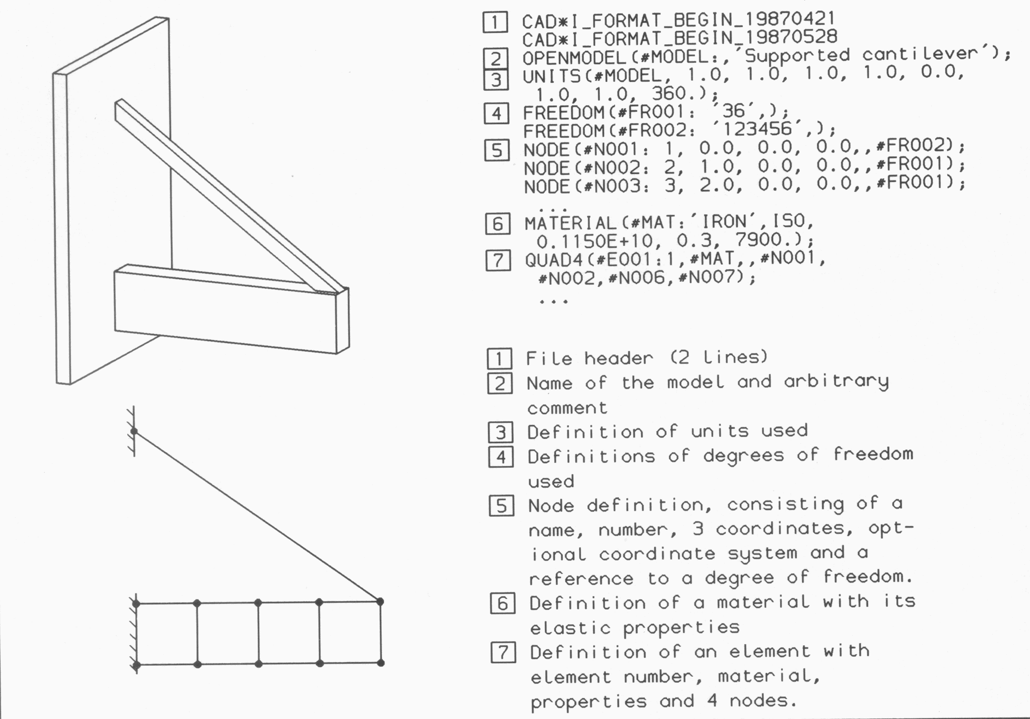
The solution has been to define files using an ASCII character set and formally define the grammar to which file contents must adhere. Reading and understanding file content is akin to program compilation. Robustness is achieved by keeping the internal structure of the file to a minimum and not overloading the meanings of operators used in the definition. The major sections of the neutral file for product analysis data are the product definition data, finite element model, analysis data and results. Within each section, an appropriate sub-structure is defined. Fig 2.4 shows an example of a neutral file. At present, specification work is about complete and interfacing software is being developed to allow a range of finite element packages to be used with the neutral files.
Research continued on an Alvey funded project to identify objects in 2-D scenes using computer techniques. This project is a collaboration between RAL and British Aerospace, Bristol University, Marconi, Reading University, Royal Signals and Radar Establishment, Standard Telecommunications Laboratories and Surrey University. Work at RAL has centred on various aspects of the use of contextual information in pattern recognition.
Descriptive labels need to be assigned accurately to objects in images. This problem arises at various stages in scene interpretation. At one level of interpretation, objects may be connected regions of similar pixels which may belong to potential categories such as road, tree, sky, car etc as in Fig 2.5 where pixels identified as belonging to particular regions are shown in the same colour. At a more basic level, the labelling operation may involve deciding whether or not a pixel belongs to the physical edge of an object. Fig 2.6 shows the result of edge labelling which draws on knowledge that edges are usually continuous and a single pixel wide. The shape of a car can be distinguished (by the eye). Further processing is needed before the object can be identified uniquely as a car by the program.
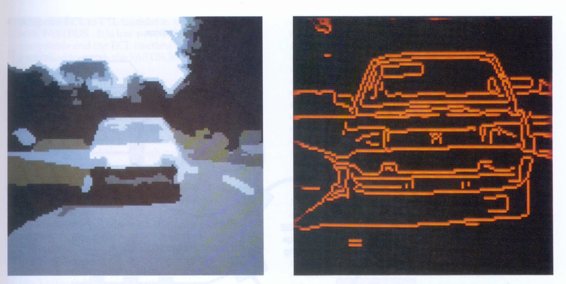
As measurements obtained from images are invariably subject to uncertainty owing to effects such as poor camera performance or noise, the resulting object labels are likely to be ambiguous or inconsistent. At the pixel level, for example, erratic or discontinuous edges may be labelled and, in the case of region labelling, regions of sky may be incorrectly identified as car. Work at RAL is concerned with improving the consistency of scene labelling using a technique known as probabilistic relaxation. This uses extra sources of information from a scene such as the spatial context of objects and prior knowledge concerning the types of label structure likely to be present (as for edge labelling in Fig 2.6).
