
This year saw the demise of the Interactive Computing Facility which had provided interactive engineering facilities for the community over the last 14 years. Information Technology activities aimed at the engineer continued on a broad front with special emphasis on integrating results into a common environment.
A Technical Group set up by the Engineering Board in 1973 recommended the development of an Interactive Computing Facility based upon GEC and Prime minicomputers located in university engineering departments and connected by a network so that users in any location could gain access. This network subsequently developed into JANET.
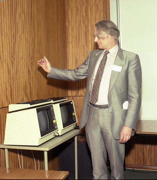
As he formally switched off the last ICF multi-user minicomputer at a ceremony attended by some 50 guests at RAL, Professor A MacFarlane commented that 30 March 1990 marked the end of an era (Fig 2.1).
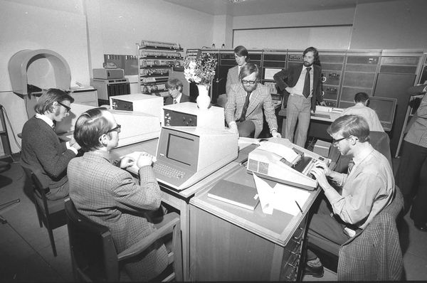
The first machine, a Prime 400 costing £81,000 with 192 kbyte of memory and 2#215;80 Mbyte disk space was installed at RAL on 3 December 1976. (For comparison, a modern workstation with ten times more power, memory and disk space can be acquired for less than half this sum.) ICF eventually installed 12 GEC and 10 Prime systems. Many of the improvements to the operating systems were subsequently incorporated into future releases by the suppliers.
In parallel with the hardware developments, Special Interest Groups (SIGs) were established covering Artificial Intelligence (AI), Digital Design, Circuit Design, Control, Electromagnetics, Finite Element and Architectural Design. This resulted in the purchase and support of many application software packages during the lifetime of the project. SIGAI became part of the Alvey Programme, the major UK Information Technology initiative of the '80s.
Between 1976 and 1990 about 20,000 users benefited from the service offered on the various machines. The estimated total cost of the ICF service, including capital, maintenance and manpower was #163;20M. ICF allowed researchers to concentrate on their research and enabled innovative research projects to be undertaken which would not otherwise have been possible.
One spin-off was the machine donated by Prime for use by local schools. Another was very early recognition of the possibilities of what are now graphics workstations. ICF was also a model for the Alvey infrastructure support.
Computer-aided design systems are nowadays in widespread use throughout industry. It is increasingly important that data can be exchanged between such systems in an effective manner. Frequently, engineering parts are designed by one company and manufactured by another. Even within a single company, different computer models are used for, say, electromagnetic analysis and thermal analysis and the results of the electromagnetic analysis need to be passed to the thermal analysis model.
The International Standards Organisation (ISO) has addressed this problem and is developing the Standard for Exchange of Product Data (STEP). An important and innovative aspect of this standard is a strict separation between descriptions of the semantics (the meaning) of the data and the syntax of the exchange format. The standard contains data models of a number of application areas and uses a data modelling language (Express) specifically developed for this purpose.
The language has a formal definition which makes it possible to build an Express compiler which reads and interprets the data model and enables the syntax and part of the semantics of the data model to be checked. The importance of such a compiler was recognised at RAL and a project undertaken to write an Express compiler. The compiler acts as a front end for related RAL software which has been produced as part of the project. For example, it is possible to obtain information about the data model from the compiler and therefore the file reading software can do much more extensive error checking.
It is possible to build a database in a format compatible with the Express data model. Access routines to such a database can shield the user of the database from implementation details and need only deal with Express information. From the user point of view, it is as a database were operating directly on the Express data model.
For a number of years, the Laboratory has had a substantial role in the development of both the STEP standard and this supporting software. Its Express compiler and file reader have been distributed to a number of academic and industrial organisations worldwide. It is also expected to be a key element in the EASE software Environment.
In December 1986 a study was commissioned to explore the notion of a software environment, subsequently known as the Energy Kernel System (EKS), which would make model development and maintenance easier. This resulted in a collaborative research effort at the Universities of Bath, Newcastle and Strathclyde and at RAL funded by the Environment Committee and through the Engineering Applications Support Environment (EASE) programme. The objectives of EKS are to
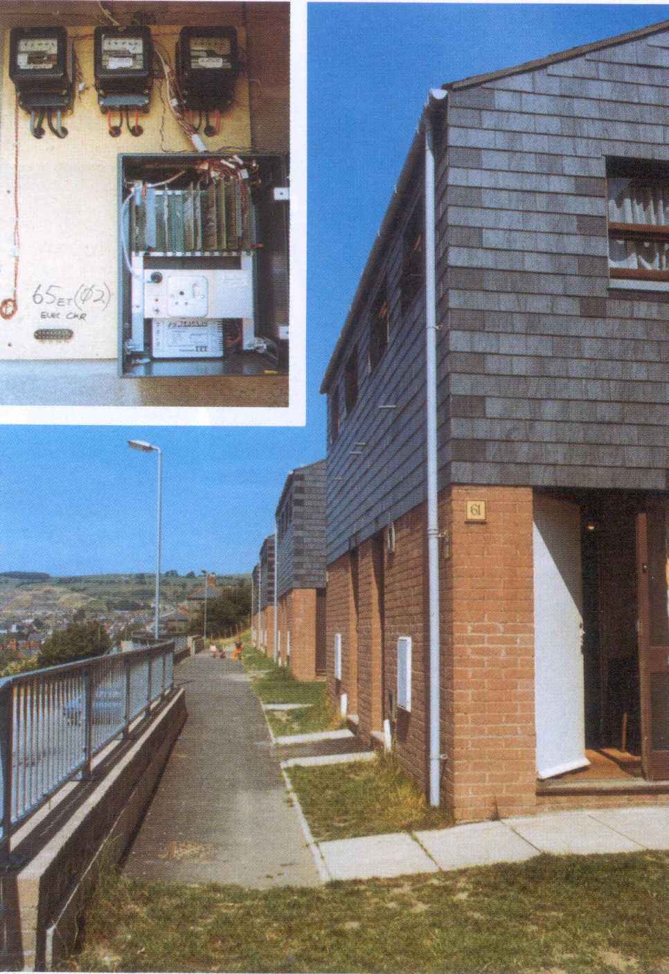
EKS uses an object-oriented architecture to create models from templates supplied by the user, a researcher interested in model building or energy simulation. In its present form the core of EKS is an object oriented database which holds the classes necessary to build a wide range of models and provides a secure mechanism by which these classes can be put together to form the model. Fig 2.2 is an example of an experiment set up to provide data for models of this type.
EuroWorkStation (EWS) is an ESPRIT project aimed at developing a high power graphics workstation via a collaboration between various European academic and industrial partners.
3D graphics are becoming more widespread so there is an increasing need for input devices to control this power more effectively. One such device is the DataGlove (Fig 2.3). This is a black lycra glove which uses optical fibres running along the back of the hand to detect flexion in the wearer's fingers. It also carries a Polhemus cube moving in a magnetic field to detect the position of the hand in 3D space.
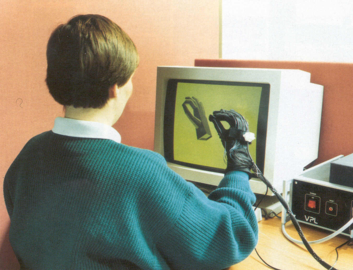
Part of the EWS project compares the use and effectiveness of the DataGlove as a 3D input device with more conventional 20 mouse input. It appears that when the glove is used in conjunction with a virtual tool (such as making the user's index finger into a pointing device) manipulation of objects on the screen becomes very much easier.
People are used to using hand gestures in everyday life. A gesture-driven window manager has been developed which enables the user to, for example, push a window around the screen as though it were a piece of paper on a desk and alter the size of that window by pinching a corner and stretching it to the required size. This approach holds much promise for exploiting this type of device for the complex interfaces of the future.
The graphical user interfaces provided on powerful workstations have made complex software much more accessible to engineers and scientists but exploiting the full power of the application software is still difficult. Applications are now so user-driven that they depend on users for every step of their operation. More complex uses are still only expressible with a text command interface.
RAL has a research project to develop methods of controlling one application from another and allowing the control of such applications to be automated. This has previously been possible only with textual command languages which are difficult to learn and remember. The ability to combine existing functions with others to form specialised new commands encourages users to make their own work more productive by automating otherwise tedious procedures. This brings the power of programming to the end-user but in a manageable form. The alternative (of providing endless lists of options, most of which are never used) is unworkable in a computing world which grows ever more elaborate.
A library of support software has been built which enables applications to share control with the user and with other pieces of software. For example, by combining basic tools such as a simple text editor, a file browser and a tool for glueing windows together it is possible to create electronic mail browsers, bulletin board browsers and many other tools which provide front ends for more traditional tools. Some examples of this kind have already been built and are being used by the project team to develop new software.
There is a need to develop ways of expressing programming-like concepts using a graphical interface, without the need for the end-user to be a programmer in the conventional sense. Some methods to support this are being borrowed from the world of visual programming (building programs using icons instead of keywords). Work is being done to create a tool which drives other applications from a simple program generated graphically by a user. This will allow users to encapsulate common sequences of actions and give them new names, thus expanding the richness of their computing environment in relevant ways.
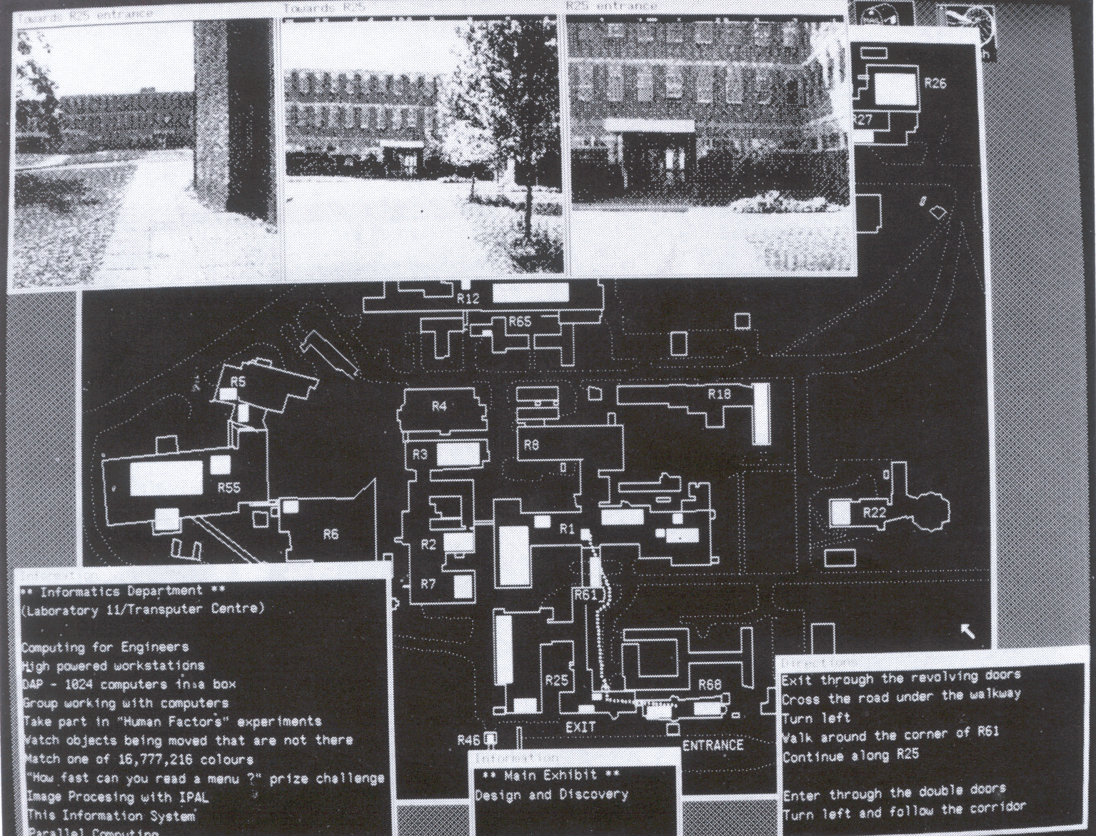
This was designed and implemented for the Laboratory's Open Days in July and it was used by over 600 people seeking information about demonstrations and facilities. The system used high-resolution graphical workstations and the local area network to demonstrate a representative high quality graphic user interface.
The system consisted of six remote workstations at prominent positions around the Laboratory and up to six 'master' machines run by experienced computer users. A visitor pressed the space bar to make an enquiry. A master machine picked up the request and its user contacted the visitor by telephone. The visitor could, for example, be given information on screen about nearby or other demonstrations, his/her present location or those of bus stops or refreshment facilities, as the software running on the master machine continuously copied its display to the remote machine.
The display consisted of a map of RAL with all buildings and main roads marked. When places to be visited had been selected the system drew the route on the map and displayed pictures of prominent buildings that would be passed (Fig 2.4). A laser printer at each remote machine allowed the map, route and instructions to be printed.
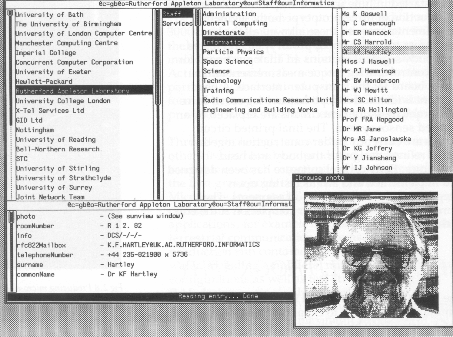
Recent standardisation by ISO and CCITT is making the concept of a global Information Directory a reality. The aim is to facilitate communications between applications, through information stored on objects of interest in a networked environment, and between people, through information such as phone numbers and electronic mail addresses.
The Directory has a distributed structure, with local information typically maintained at the local Directory System Agent (DSA). DSAs cooperate over wide area networks as necessary, so that the user sees a single global tree of information.
RAL is participating in the UK Academic Community Pilot Project to establish DSAs at universities and a DSA at RAL has already been populated with contact information for all staff. Simple access to the Directory has been provided to users of the Laboratory's IBM mainframe computer but, to take full advantage of the ability to browse the global Directory, a more advanced interface running on a graphics workstation has been developed (Fig 2.5).
Plans for this work include further development of user interfaces, with extended availability within the Laboratory. Consideration is also being given to storage of types of information other than simple contact points.
A project aimed at demonstrating the use of transputers for real-time control is being carried out at the University of Salford. It is funded through one of the community clubs run by RAL as part of the SERC/DTI Transputer Initiative.
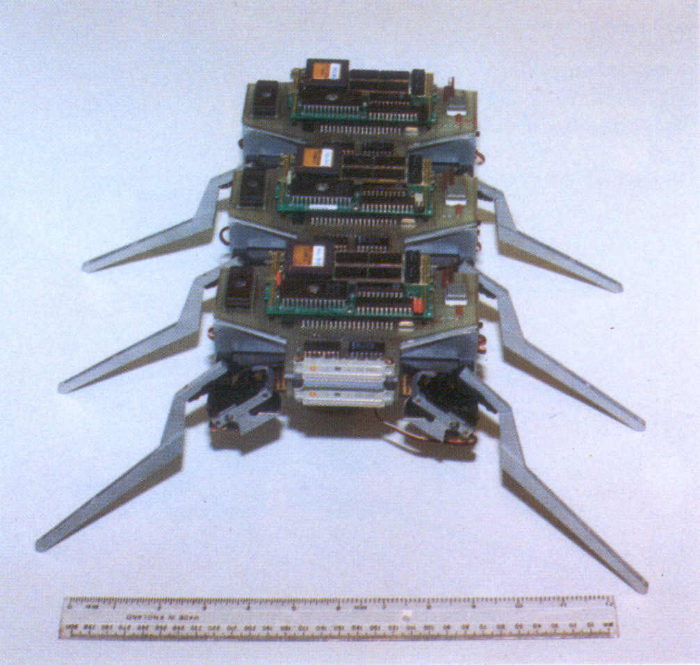
The demonstrator will consist of a six legged mobile robot which will be able to track and follow in real time the motion of another moving object (eg a person). The robot will be approximately 40 cm long, have a leg span of 26 cm and weigh 1.5 kg (Fig 2.6). A novel feature of the hexapod is that it will consist of completely self contained leg-pair segments and one head segment which can either operate in isolation or be connected together to produce the overall demonstrator. All the segments will possess their own transputer, electronics and power supply. An individual body segment will exhibit a basic stance behaviour when in isolation. Connecting additional segments will allow overall behaviour to be improved, up to the point of the robot being able to walk and negotiate small obstacles. The final addition of the head segment, containing object detection sensors, will provide steering control for the attached body segments.
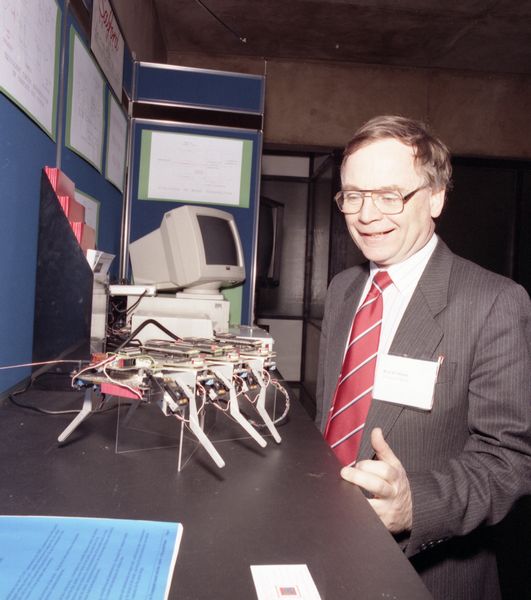
The segmental approach is aimed at demonstrating the ability of multiple transputers to control in real time a complex twelve degree of freedom device, the extensibility of using transputers by being able to connect additional segments together in order to achieve the desired demonstrator performance, and the cost effectiveness of the transputer approach given the imposed engineering constraints.
Work started in June with the mechanical design and construction of three prototype body segments. Experimentation with these allowed all the body electronics to be designed, prototyped and tested. Each body segment contains an analogue board for servo control and leg torque measurement and a digital board for the transputer interface. A head segment is identical except that two leg servo drive and torque measurement circuits are replaced by an infrared sensor system. The final printed circuit boards are currently under construction together with a refined design for the body and head mechanics. Early control software has been designed and implemented and awaits testing upon integration of the final hexapod segments. The demonstrator is scheduled for completion at the end of the year.
