
Esprit (European Strategic Programme for Research into Information Technology) Project 2463, ARGOSI - Applications Related Graphics and OSI Standards Integration, started on 1 March 1989 and is of 3 years duration. Eleven organizations are now involved in the project:
The project arose from the recognition that within ISO/IEC, as elsewhere, standards for computer graphics and standards for Open Systems Interconnection have been largely developed in isolation and little serious attention has been paid to issues of integration. The objectives of the project are twofold:
As the project title implies, the project is driven by applications and their requirements in terms of graphics and networking services in combination. The project started by looking at how applications could be classified according to these requirements. Effon was then devoted to studying how the requirements emerging from this classification work could be satisfied by existing ISOIIEC graphics and networking standards and to what extent new standards or amendments to existing standards are necessary.
To demonstrate what is possible now with existing or emerging graphics and networking standards and international public data networking facilities, an application demonstrator has been developed. The project is concluding with a study of the effectiveness of the integration of graphics and networking services achieved in the demonstrator. Recommendations have been made to ISO/IEC for improvements in a number of standards, some of which are referred to later in this paper.
A broader overview of the activities in the ARGOSI project is given in:
J.J. Bardyn, R.A. Day, D.A. Duce, J.R. Gallop, L. Mistral, and D.C. Sutcliffe (1991), The ARGOSI Project for ISO/IEC Graphics and Networking Standards, Proceedings of Esprit' 91 , pp.512-528, Commission of the European Communities.
The ARGOSI prototype application was conceived to demonstrate a typical application that utilized standard graphics and OSI services working together. The aims of the demonstrator were:
The choice of the prototype application came out of work in the project on classification of applications in terms of requirements for graphics and networking services. An information system for European road freight operators was identified as an appropriate prototype application, and CGM and FTAM as the appropriate standards as the starting point for providing the required combination of graphics and networking services. The scenario is that of a road freight operator who wishes to plan a route across Europe, avoiding any traffic difficulties, using a graphical interface. The road freight operator uses the application from a consultation workstation where he is able to draw the proposed route on a map, enter the dates of the journey and request details of the traffic difficulties affecting a journey along this route between the dates. The traffic difficulties falling between the specified dates are displayed on the map together with the route. The map, route and difficulties may be zoomed and panned. The operator may then alter the route or dates to avoid these difficulties and make a further consultation based on the new route.
The aims of the demonstrator (enumerated above) were made specific to the chosen application:
This application is typical of a wide class of applications in which a large volume of unchanging data is overlaid with a smaller volume of data which does vary over time and may be held remotely.
In broad outline the Europe map is covered by a grid of squares, and each country has a database of difficulties covering the squares allocated to that country. When the operator has defined a route, the difficulties for the squares covered by the route are transferred from the appropriate difficulties databases and displayed as an overlay on a locally stored Europe map. The idea is shown in Figure 1.
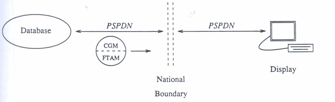
The graphical information (map, traffic difficulties) is represented by CGMs; FTAM is used to transfer CGM information and X.25 PDNs provide the basic network service.
At a finer level of detail, the application consists of two independent programs; the consultation program is the unit which enables the operator to consult the traffic difficulties. The creation program provides the interface through which traffic difficulties are entered. Both programs were split into application, graphics services and networking services modules for the purpose of design and implementation. The architecture of the consultation program is depicted in Figure 2.
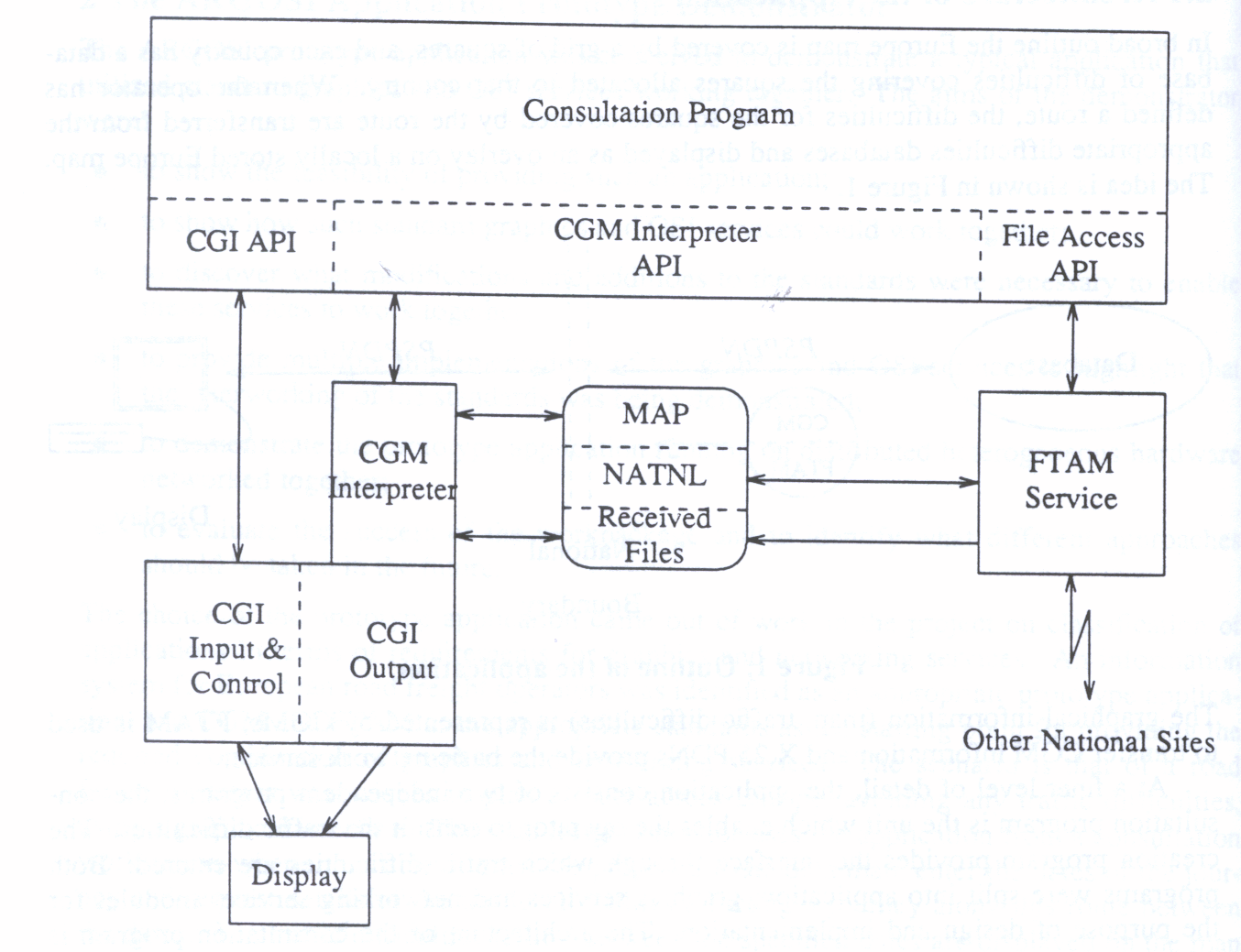
The graphics architecture consists of a CGM interpreter and a subset of the Computer Graphics Interface (ISO/IEC 9639) to display CGM pictures. CGI services are used to zoom and pan the map, route and difficulties. CGI input facilities are used to enable the operator to define a route and to make choice selections from menu items.
FTAM is used to provide the traffic difficulty pictures from the national sites (both local and remote). A square server provides the address mapping between square name on the Europe map and CGM picture address for use by OSI services.
The PSPDNs involved in the demonstrator were:
Experiments carried out earlier in the project demonstrated that the necessary connectivity between sites was available for the demonstrator. They also showed that 3kbps was a reasonable throughput at the application level to expect between the partner sites.
It is clearly extremely wasteful of resources to transfer an entire CGM between sites if a single or small number of pictures within a metafile is all that is required. The next section discusses how access to subunits in a CGM through FTAM has been provided.
Before describing how CGM is mapped onto FTAM, it is useful to give short overviews of both CGM and FTAM.
Graphics metafiles provide a mechanism for storing graphical information for purposes such as transfer to another system for display, storing partly developed pictures for later modification and storing pictures for incorporation into documents.
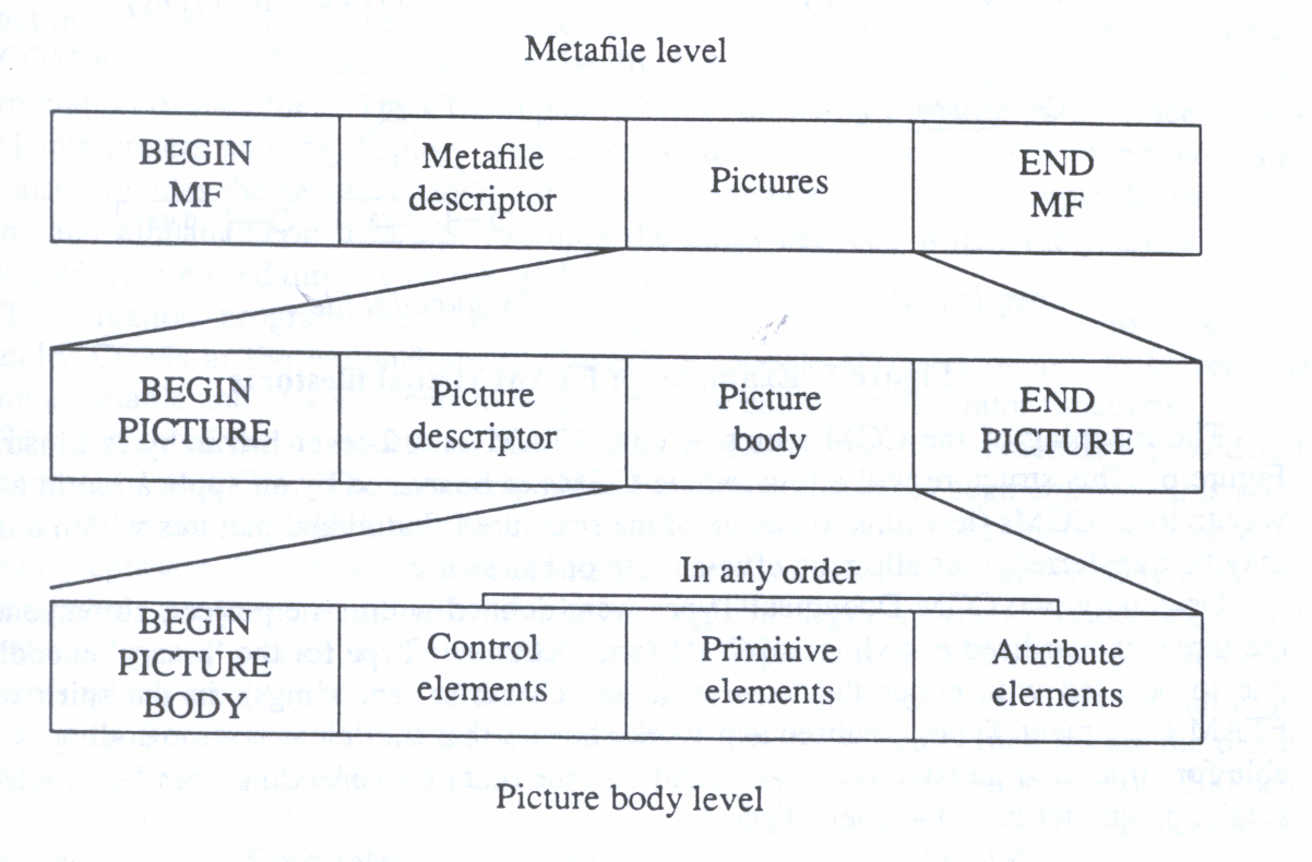
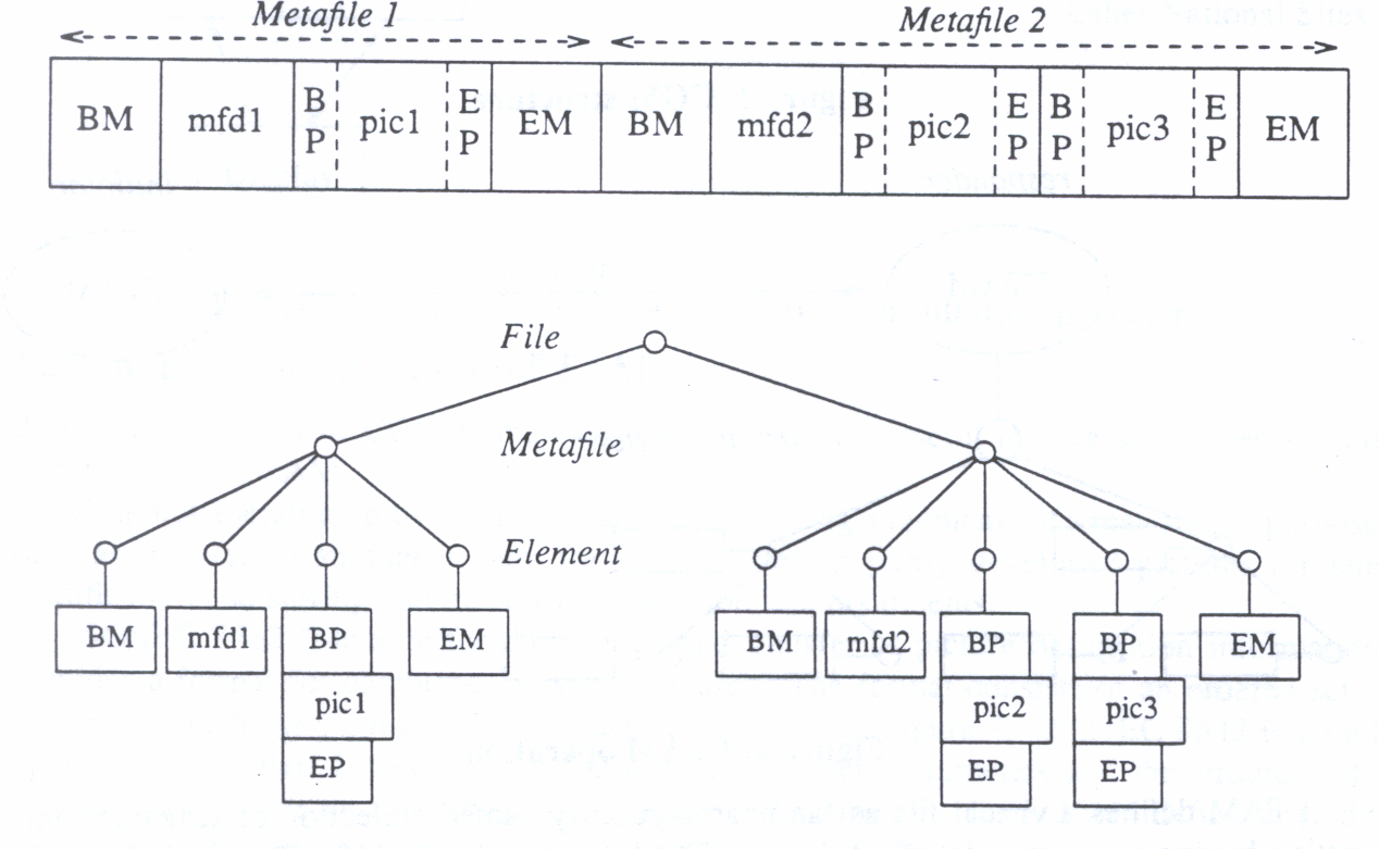
IS0/IEC 8632 'Metafile for the storage and transfer of picture description information' provides a format for capturing 2D static pictures. The format consists of an ordered set of elements, which have a hierarchical structure as shown in Figure 3. ISO/IEC 8632 is a multipart standard. Part 1 specifies the CGM elements, their parameters and the structure of a metafile (constraints on the permitted sequencing of elements). Parts 2 to 4 define three different encodings to represent the abstract syntax of the CGM elements, character encoding, binary encoding and clear text encoding. These have different characteristics relative to ease of generation and interpretation, size of the resulting metafile and ease of transmission between systems.
ISO/IEC 8571 'File Transfer, Access, and Management' (FTAM) provides facilities for remote access to a filestore (see Figure 4). The ways in which real filestores are implemented vary considerably between real existing systems. Different systems have a wide range of styles for describing the storage of data and the means by which it can be accessed. A common model for describing files and their attributes is needed before services, protocols and procedures for file transfer, access and management can be used in an OSI environment. Such a model is provided by the FTAM virtual filestore.
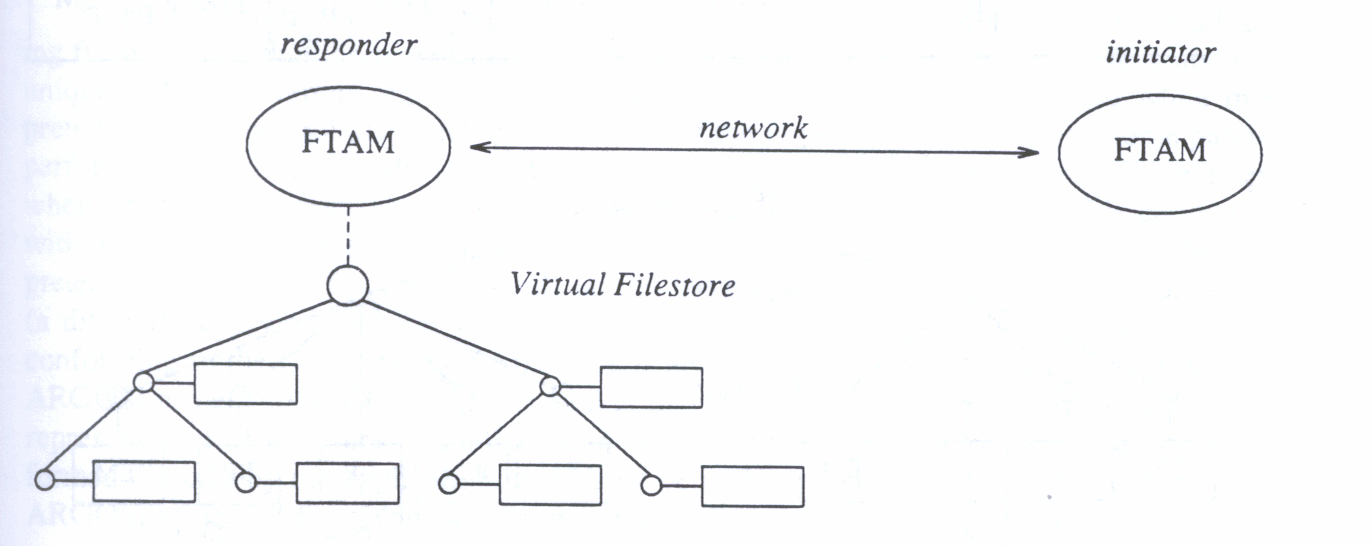
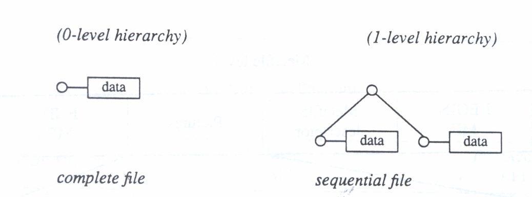
FTAM defines a virtual file as an unambiguously named collection of structured information having a common set of attributes. The basic access units of a file and their relationships are described by the file access structure. This is a tree structure that describes the file in terms of the units which can be accessed separately (FADUs - File Access Data Units). A FADU is the minimal access unit and is a subtree of the hierarchical file; the actual data units are associated with the nodes of the tree, and can be identified by their relative node name. This is illustrated in Figure 5. (Note that the levels in the hierarchy conventionally begin at 0!)
FTAM introduces the idea of a constraint set, a set of restrictions and refinements of the general file model, tailored to the needs of a particular class of applications. A Document Type defines inter alia constraints on the file structure, the data types forming the data units and how the record structure of a real file maps onto the FTAM virtual filestore.
The mapping of the CGM structure onto FTAM as a 2-level hierarchy is illustrated in Figure 6. This structure will allow remote CGMs to be treated by an application in a similar way to local CGMs (ie with knowledge of the structure). Individual pictures within a metafile may be transferred, thus allowing efficient use of bandwidth. Originally two CGM Document Types were defined within the project, corresponding to the three standardized encodings of CGM (one Document Type for the binary encoding and one to be used with either the clear text or character encodings), in the spirit of other FTAM Document Types. Subsequent work showed that the clear text encoding is unsuitable for structured transfer via FTAM, and that the other two encodings can be handled via a single, parameterized Document Type.
The CGM document type has been presented to ISOIIEC for standardization and has now been registered. Access to FTAM services in the ARGOSI demonstrator is through an Application Program Interface (API) defined for the C programming language, based on the context free file copy service subunit of the MAP/TOP 3.0 API. The service offered by this subunit was extended to allow asynchronous operation (the ability to have underway simultaneously several file transfers, all initiated from a single process via the API).
As outlined in section 3.1, the graphics services are composed of a set of modules based on the CGM and CGI. The CGM tools can be divided into three parts: generation, editing and interpretation of metafiles. The CGI implementation primarily provides an interface between CGM interpreters and the display. The latter is addressed through the X Window System. CGI also provides the necessary tools for input of graphical data (for example the route to be taken) and alphanumeric data (for example the dates between which the journey is to be made), which are used directly by the application.
The creation program uses the CGM generator and editor modules to modify the difficulty CGMs at the national sites. The editor module allows a picture to be reopened within a metafile and new elements to be added at the end using generator functions.
The design of the demonstrator also makes extensive use of functionality provided by Amendment 1 to CGM. The most important functionality used is segmentation; this allows subunits to be defined which can be instantiated within pictures. Segments are used extensively to represent the symbols which denote the various kinds of difficulties. Descriptions of these symbols are stored in metafile descriptors as global segments (meaning that they can be instantiated by any picture in the metafile). Pictures representing difficulties contain metafile elements which create instances of these symbols at specified locations. This was an important decision from a communication point of view since the difficulty pictures are the pictures which are accessed remotely using OSI services. A typical segment contains about 200 octets while the COpy SEGMENT element contains 24 octets. About one hundred occurrences were used in the demonstration (this number was limited only by the effort put into creating these symbols). This represents a gain of 15200 octets. The use of this facility has an important impact on the feasibility and the success of the demonstration.
Some difficulties were encountered during the implementation of the demonstrator, arising from the fact that the representation of a picture as a sequence of metafile elements is not unique. Many different sequences of elements can produce the same picture when interpreted. One of the toolkits which was the basis of the implementation work by some partners performs an optimization during metafile generation, only outputting state-setting elements when strictly necessary. This feature has unfortunate consequences when used in conjunction with application data elements used to control whether subsequent elements should be interpreted (represent a traffic difficulty relevant to the proposed dates of the journey) or skipped (a difficulty applying to some other time). The optimization certainly produces a metafile conforming to the CGM standard, and there is an argument that the use made of CGM in the ARGOSI project goes beyond the standard in that the standard does not guarantee a canonical representation of a picture. Equally, it can be argued that optimization should either be performed directly by the application, or at least be under the control of the application. In the ARGOSI project, the problem was solved by disabling the optimization feature.
Several different implementations of the standards used have been employed in different realizations of the prototype application. This was facilitated by careful definition of the interfaces between the application and the graphics and OSI services.
Three implementations of FTAM (Tecsiel, Marben (from Thomson), and ISODE) were used, each extended to provide support for the CGM-FTAM document type. Two different CGM toolkits, both extended to provide support for Version 2 CGMs (which incorporate the segmentation functionality defined in Amendment 1 to ISO/IEC 8632), were used for the generation and interpretation of CGM metafiles, using a common CGI for graphical input and output. Each of the common applications (consultation and creation) made use of the different FTAM and CGM software in different combinations. The FTAM implementations interworked exchanging CGM data and the CGM toolkits were able to interpret CGMs produced by each other. The whole prototype application highlighted the interworking of graphics and OSI standards together and with each other.
The route planning application was demonstrated on the ARGOSI stand at the Esprit '91 Conference Exhibition. The consultation program was demonstrated on a Sun SPARCstation 2, a CETIA workstation and a Hewlett-Packard workstation at the exhibition. These workstations were connected to the Belgian PTT's public X.25 network. National sites were provided by a Sun server at RAL, UK (for the UK), the CETIA workstation at the exhibition (for France), a Sun workstation at INRIA, France (for Germany), a Hewlett-Packard workstation at Tecsiel, Italy (for Italy and central Europe), and a Sun workstation at COSI, Italy (for southern Yugoslavia and Greece), connected to the respective national X.25 networks. All three FTAM responder implementations were used to give access to the traffic difficulty CGMs. The consultation program was used with both the CGM interpreter implementations and all three FTAM initiator implementations.
The application was successfully demonstrated throughout the duration of the exhibition. Routes were planned across the whole of Europe and traffic difficulties fetched from each of the national sites.
The application was demonstrated at the ARGOSI Workshop on Distributed Window Systems as an example of how graphics might be distributed across a network. Although the primary purpose of this demonstration was to show the distribution of stored graphics using a bulk data transfer and access service, the circumstances of this particular demonstration meant that there was an additional level of distribution of graphical data. This involved the use of X, and a schematic diagram of the configuration used is given in Figure 7.
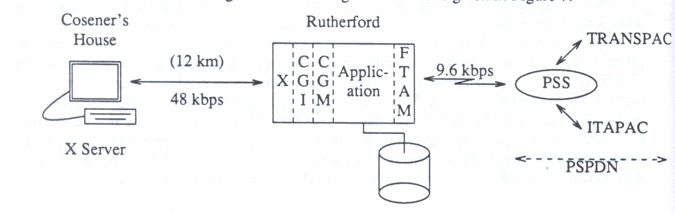
Because there were no PSPDN facilities at the Workshop venue (The Cosener's House), it was necessary to run the application at Rutherford Appleton Laboratory, about 12 km distant. There was a 48 kps serial line between the two locations, and this was used, along with suitable MAC-level bridges, to provide connectivity between the Ethernet at Rutherford to which the system running the application was attached and the X server at The Cosener's House. Thus it was possible to run an X session between the two - in this case over TCP/IP, although it would have been possible to run the session over an OSI stack if desired.
The application was demonstrated completely successfully, in this instance with the consultation process at Rutherford retrieving CGM pictures via FTAM from sites in France and Italy. The application displayed the results on the display of the X server at The Cosener's House - this included maps represented as line drawings with filled (colour) areas, along with line drawings of various symbols representing traffic difficulties. Input from the X server was also processed, in the form both of keyboard and of mouse input. The latter involved tracking of the mouse by the application so that it could provide cursor tracking and rubber banding during the part of the demonstration when the user selects the route to be taken.
The nature of the input process in particular is critical in terms of response time between X server and client (ie the application) if a response to mouse movements is to appear acceptably smooth to the user. In practice this was found to be perfectly adequate with the 48 kbps link available. It is interesting, therefore, to calculate a rough budget of the time taken for each part of this process, and to compare this with the conventional wisdom that a response needs to arrive within approximately 100 ms of the user's input to achieve the illusion of spontaneity.
The nature of the protocols supporting the X session mean that even for a simple exchange of X data (such as a mouse event) about 70 bytes must be sent in either direction. At 48 kbps this implies that approximately 25 ms are required for the packet to be transferred from the X server to the client, allowing for the overhead in bandwidth used by the bridges and also for delays as the packet traverses the bridges. Another 25 ms is required for the response to travel from X client to server. In addition there will be some processing time at the X client itself. An estimate of 20 ms is reasonable - measurements of the character echo time of a xterm client carried out as part of the work of the UK Joint Network Team's SIG on X-Windows gave a value of 10 ms, and the processing involved in the present application is higher than in that case. Thus the total round-trip delay can be estimated at 70 ms, which is comfortably within the limit of 100 ms. In practice no time lag on operations such as rubber banding was noticeable.
Decreasing the bandwidth available to 20 kbps (a value often suggested as a minimum for satisfactory X performance) would imply that the time to transfer a packet from X server to client would rise to approximately 45 ms, and that the total round-trip time would be an estimated 110 ms. At this value it is likely that the user would begin to notice a time lag in rubber banding. In fact during the setting up of the demonstration a link bandwidth of 32 kbps, rather than 48 kbps, was used for operational reasons, and the onset of time lag in this type of operation was then just noticeable.
This paper has given an account of the ARGOSI prototype application demonstrator. Overall the route planning application has been found to meet the aims of the demonstrator in the following ways:
There is a philosophical point alluded to in the last remark concerning the use of FTAM document types in this type of context. While the specification and implementation were successful, the strategy needs to be considered further in the light of the possible appearance of many more FTAM document types in the future. In the ARGOSI implementation, knowledge of the document type, and the files it described, was built into the FTAM responder. However, the document type only related to one of the three possible encodings for CGM and only represented a CGM with a two-level hierarchy (as discussed earlier). To have included support for those extra features would have needed considerably more software to be added to the responder. Thus, it may not be feasible to provide built-in support for all document types when a large number come into existence. Secondly it resulted in the FTAM service needing to do a partial implementation of the CGM interpreter to generate an index to the location of pictures in metafiles, which needed to be done elsewhere by the CGM tools. Consideration needs to be given to how document types can be implemented without building all the knowledge of the physical file structures involved into the FTAM service.
