
The Brooker-Morris Compiler-Compiler has been implemented in part on the G21. This first chapter will give details of how to use the C-C on the G21, the limitations of the system, peculiarities of the G21 system, etc. It should be pointed out that this implementation was carried out purely as a means of educating the author in the detailed coding of the C-C. Consequently, no claims for efficiency or usefulness are made. In fact, unless the system is run as a 64k program, it is only useful for student examples and familiarizing the user with the system. This, in part, is due to the crude method of implementation.
Following chapters will describe the bootstrapping process used to implement the system from the Atlas version and details of how the fundamental Master Phrases are implemented.
At the moment the Compiler Compiler is situated on a Logical File Type. It requires approximately 60 blocks and a user may either use the standard version or obtain a copy of the system on his own logical file. The current custodian of the system will know the position of the C-C. At the moment it resides on FILE 46/1 of User CS07FH04, but this will probably be changed.
Details of the facilities available in the C-C are given in the paper, "The Compiler Compiler" in the Annual Review of Automatic Programming Vol.III. Knowledge of this paper is assumed and remarks will be made with respect to it. An example of a simple C-C run on the G21 would be:
$$330 AND CS07FH04 HOPGOOD
AN FILE 46/1(12);  FILE 48/1(13); TEXT;
       PHRASE [XYZ] =: AB, CD, EF
       DEFINE COMPILER 13
AN RUN, (12), TAPE;
$$
This illustrates the method of bringing down the Compiler-Compiler and also the Master Phrase for redefining an augmented version of the C-C. The 'DEFINE COMPILER' Master Phrase has just one argument which is the number of the logical file that the system is to be dumped on. In the example the phrase XYZ has been added to the C-C.
In order to run the C-C "as a 64k program it is necessary to patch two instructions in the C-C. This can be done by UPDATE and the above program would then be:
$$ 330 AND CS07FH04 HOPGOOD
AN FILE 46/1(12); FILE 48/1(13);  TEXT;
    LXS  12;
    PATCH  12021, 120000  .160000 ;
    TRA 12000;
    PHRASE [XYZ] = AB, CD, EF
    DEFINE COMPILER 13
AN  RUN, UPDAT, TAPE;
$$
Note that the C-C defined will now be a 64k version and to convert back to a 32k version requires:
PATCH 12021, 60000 .67776;
A 64k program cannot, of course, be run from the teletypes in the normal manner.
The present storage layout is:
            Input Buffer                 11300
            Masks and useful constants   11540
            B variables                  11600
            Index                        12000
            G21 op-code skeletons        14000
            Record Store                 15000 to 52000 (approx)
            Stack                        60000
            Chain                        67776 (downwards)
The positions of stack and chain are moved in the 64k version so that about 16k of chain store is available and the record store can increase until it hits the monitor. If the record store does become this large, then it would be necessary to increase the LFT size from 60 to 70 blocks.
At present an interactive scope version is under construction which also uses the space below 11300.
The Bootstrap part of the C-C defined in Chapter 2 is machine dependent, and this section will describe G21 features of the bootstrap. This part was written in SPITE using a set of Macros which simulated the Atlas Machine Orders in the original version. It is hoped to be able to use the same macros in the 360-67 version.
The routine entry sequence on Atlas used the B variables B91, B92, B93, B94 and B99. The G21 version does not destroy these variables. B99 is still used by the END sequence.
This routine takes the input and produces an internal form which is equivalent to the G21 internal character codes with the meta-characters defined as follows:
             eol           104
             EOL           107
             comma         105
             [             106
             space         101
The character 10 is used in place of ? and the operators ≤ , ≥ are replaced by < =, > =. The equivalence sign º is written as (=).
Routines added to the normal C-C routines are:
Two additional Master Phrases added to turn listing of the input on and off are:
     LIST
     DO NOT LIST
The Atlas PLANT basic statement has been replaced by the statement:
LOAD [MNEMONIC][COMMA][ABN][COMMA][ADDRESS][REG?] INTO [B}[SEP]
where
[ADDRESS] = [WORD], · [BFJX][N] + [WORD], ·[BFJX][N]
[BFJX]   = B,F,J,X
[REG]    = [COMMA][ABN]
[MNEMONIC]= G21  MNEMONIC
The field [ABN] is a node field which is compulsory. The phrase [REG] defining the register part can be ignored. [B] defines the location where the instruction is to be placed and is automatically incremented.
In order to understand the address part of the field it is necessary to first define the G21 fields for the various fields in the data described in Chapter 2.
Field      Bits
  A        0 - 15
  F       16 - 17
  J       18 - 19
  S       20 - 21
  Z       22 - 31
As the higher fields appear in the operation part of an instruction it is necessary to provide.constant locations containing the relevant masks for these bits. The masks for the F and J fields are stored in addresses F1, F1, F2, F3, J2, J4, J6. Also, it may be required to put an index position or B variable address in an instruction. The dot notation is used to denote that the address itself is required rather than the contents of the address. For example, if B32 = 6 then
LOAD CAL, 2, B32 INTO Bl
will load the instruction CAL 2 6 while
LOAD CAL, 2, .B32 INTO B1
will load the instruction CAL 2 /11640
The +[WORD] in the second [ADDRESS] alternative will add the value of word to the address defined in the first part, · [BFJX][N].
This, to a large extent, was Atlas oriented in the definition of constants. This has been replaced by the following definition:
[WORD] = [ADDR], ([ADDR]), -[N], [N][JF?], [JF]
[JF]  =F1,F2,F3,J2,J4,J6
The G21 version of the C-C is approximately equivalent to the Atlas version with the Auxiliary Statements undefined. On the Atlas version all simple forms of the Basic Statements were compiled rather than interpreted. On the G21 all Basic Statements are interpreted. No 'COMPILER' versions of the Basic Statement routines have been added. This was done partly because of storage problems and also because this is the point where G21 dependent routines would have to be added. As the first aim is to have the C-C implemented on the 360-67 this work to a large extent would be wasted.
The Auxiliary Statements have been omitted because, without the COMPILE versions of the Basic Statements, it is impossible to get the routines compiled in the 32k G21 store. These are all written in terms of CC orders and very little work is necessary to add these if a 360-67 version becomes available.
To initialize the C-C so that it is capable of self-extension and therefore able to build itself up to the required level we need a set of routines, tables and dictionaries which must be provided in a language independent of the compiler. This set is as follows:-
These routines need not be in their final form but must be capable of recognizing and generating ITEM routines. The final forms, of these routines can then be defined as ITEM routines replacing these temporary Versions. However, DOWN and UP will be inserted in their final forms as most of the mechanism is required; also the INDEX and routines 238 and 266 which are machine dependent and will not be changed.
The INDEX is a set of fixed locations which we will denote by X0, X1, etc., up to a figure larger than X300 and less than X1024. These provide locations for storing fixed global parameters of the system in a similar manner to the B variables. Their main purpose, however, is to contain the entry points to all routines and dictionaries. All routine and dictionary accesses are made via the address in their index position so that movement of a routine only requires changing the contents of the index position. Each routine has a number associated with it which corresponds to its index position, Besides the address of the routines each index entry contains a two-bit flag field F which is used to differentiate between different types of entries:-
As the Item Assembler is capable of defining all 4 types of entries in the record store but without the mechanism for differentiating between them, the Flag bits for entries being provided by the Item Assembler must be preloaded into the Index. Also, of course, the entry points for the routines in the.bootstrap must be inserted in the Index.
The complete list of entries necessary is as follows:-
The routines defined in the bootstrap must also have their entry points loaded in the INDEX. These are 130(F2), 150, 161 (F1), 214, 215, 216(F1), 222, 238, 239, 240, 241(Fl), 245, 248(Fl), 252(Fl), 261(Fl), 266, 275, 283(F1). The ITEM routine also has a subsidiary entry point at position 168 which is used to enter the routine for finding an integer arriving from the input.
In the original Atlas implementation storage was left following the INDEX so that a fast non-relocatable form of the Source Statement Analysis Routine and DOWN sequence could be inserted. This is not essential, but if implemented in this way, then storage should be reserved at this point. As it is not required until the complete Compiler has been produced, we will leave discussion of this until later.
Flag bits for the following positions must be set:-
Finally the free Index positions are chained together starting at X300. Thus X300 contains 301, X301 contains 302, and so on. It is conventional to leave the last 20 or 30 Index Positions as a set of Small Routine positions for the user and these would not be chained. On Atlas these were positions 1000 to 1024. The last chained Index was therefore X998 which contained 999 and X999 was set to zero to indicate exhaustion of chain. The number of Index Positions depends only on the amount of storage available.
The initialization routine 150 together with its subroutine 161 define the storage layout of the compiler and initialize the Stack and Chain Store.
At this stage all that is required in Routine 150 is:-
In general the user would not be expected to alter R150 but he could alter R161. (For example he might require a longer chain).
Routine 161 defines the positions of the stack, chain store and record store. In a machine with a conventional storage layout it would be reasonable to have:-
If we assume the region extends from location N to M then we require:-
B72 = N          Base of working area
B90 = N+1        Stack Pointer
B89 = M-1        Chain Pointer
The Chain should be linked as follows:-
Address   Contents>
N+3
N+4         N+1
N+5
N+6         N+3
...         ...
...         ...
M-4         M-7
M-3
M-2         M-5
M-1
M           M-3
In addition Routine 161 sets the following:-
X4 = B90
X138 = 0         Number of faults detected by Master Routine
X140 = 10        Maximum number of faults allowed by Master Routine
B74 = X232       The entry address of the transplant routine.
B86 = 0          The line number
B87 = 300        The first free Index position
B88 = X2         First free address in record store
These routines will depend largely on the particular machine available. The Compiler Compiler restricts the number of possible input characters to 127 and these are assigned the numerical values 1 to 127. The correspondence between particular characters and numerical values is immaterial and can be chosen to suit the particular peripheral equipment or internal representation of a machine.
Routine 238 is designed to read the next section of input into a circular chain list (as described in reference [6]). Each chain position should contain a number between 1 and 127 corresponding to the character found on the input. The newline character should be assigned a value. It is unfortunate that some characters may be referred to specifically by their numerical values in the Item routines. The most likely characters involved in this way will be the Newline, Space, Comma and [. It is hoped to eventually remove these by having indirect references to these via the INDEX. The amount of input in a section is up to the user but the Item Routines assume one instruction per section so that having a section equivalent to a line is a reasonable choice initially. R238 exits with the next section in a circular chain list pointed at by B61. In addition the line number B86 is updated.
Routine 261 is used to convert some characters or character strings to unique special meta-syntactic characters required for the analysis of a line with respect to the Master Phrase dictionary. In particular it removes any redundant characters. Space and erase are non-significant for example when analysis takes place with respect to the [MP] dictionary; Also,it sets the numerical value for [ and , to special values which will be needed for checking against. In the original version the position 4 for EOL (End of Line), 5 for [ and 105(8) for COMMA were chosen. On the G21, 104, 106 and 105 octal were chosen, respectively. At the moment I am unclear how necessary this change is. To allow parts of a line to act as comment all characters after and including the one whose numerical value is stored in X12 is ignored ($ will be used initially).
The output form R261 is, in general, a reduced and modified form of the original string. The Routine expects B69 to point to the input chain list and on exit will have built up the reduced line and have B68 pointing at it. The original line is unchanged and may be required if, for example, the statement is not to be analyzed with respect to the Master Phrase Dictionary. It may be worth introducing at this stage some comment convention for ignoring parts of the input section.
Initially all that is required of the Master Routine is to be able to recognize the one entry in the [MP] dictionary which is ITEM. However, before the [MP] dictionary can be replaced by its final form it will be necessary to define a routine for replacing ITEM routines. Therefore, a second phrase REPLACE ITEM is also required to be recognized. Using the notation of the instructions in the Item Routine and the form of dictionaries defined in [5] we have for the Master Phrase Dictionary 130:-
H = 56 + J2      M - word
H = 19 + F1      & - word
H = 7 + F1      & - word
C = I
C = T
C = E
C = M
H = 266          Index Position of ITEM Assembler
C = R
C = E
C = P
C = L
C = A
C = C
C = E
C = I
C = T
C = E
C = M
H = 164          Index Position of Replace ITEM routine
H = 0
H = 0
We are now in a position to define the action of the Master Routine 214. Brackets will be used in the Compiler-Compiler convention. For example (B61 + 1) means the contents of the address B61 +1. We have> therefore:-
These two routines will not be changed later on as most of the mechanism is necessary immediately, and so it is convenient to store them in their final form initially.
There are basically two different entries to. the DOWN routine. The purpose of the DOWN routine in the normal entry is to update the stack before entering the new routine. Back and forward links are inserted in the stack and work space for the new routine is allocated. Sufficient information is stored so that the UP routine can restore the state of the stack to its initial form on exit from the routine.
The subsidiary entry is the TRANSPLANT entry described in [5]. The main nodes of the analysis record are moved into the stack and the associated routine is entered. This will be described in more detail later.
The normal entry is as follows:-
(B72) = B90            Forward link
(B90) = B70 - B71      Relative position of return in old routine .
(B90+1) = B75          Old routine number
(B90+2) = B60          Backward Pointer
(B90+3) = B72          Origin of workspace in old routine
B71 = B91              Location of current routine
B75 = B92              New routine number
B72 = B90+4            New forward link position and origin of workspace
B73 = B71 + (B71+1)    Location of label directory for routine
B90 = (B71) + B72+1    New stack pointer position having moved over workspace
If the DOWN routine is entered for TRANSPLANT then entry is made at 4. In this case B77 will contain the position of the analysis record (≥ 0) and B92 set to Index position of analysis record. In this case between 6. and 7. is inserted:-
6.1  (B72+1) = B77
     (B72+2) = (B77+1)
     (B72+3) = (B77+2)
     etc.
until all &'s of top level of analysis record have been copied into stack; that is until a word without Fl set is encountered. The rest of the workspace area up to B90 is then initialized to zero. This will be discussed in more detail later.
The UP routine returns stack to the position before entry to the previously called routine which we are now exiting from. The stack must be adjusted as follows:
B70 = (B72-4)      Recover relative position of return
B75 = (B72-3)      Routine number
B90 = (B72-2)      Stack Pointer
B72 = (B72-1)      Pointer to storage area
B71 = Contents of Index position B75 = entry position of the old routine.
B73 = (B71+1) + B71 = Location of label directory
Transfer to B71 + B70.
This is only required to recognize ITEM and REPLACE ITEM so far so that it can have the following simplified form:-
1.  B43 = B62
2.  B62 = B61 ∧ A             (A = address mask)
3.  B63 = B88
4.  B68 = B90
5.  B67 = (Contents of Index B43) ∧ A
    B65 = B67 .            •   .
6.  (B90) = {B67 + (B67) } ∧ A
7.  B90 = B90+1
8.  B69 = B90
9.  B67 = B67+1
10. B43 = (B67)
11. If B43 is &, that is F1 bit set then:-
           (B90) = B62
           (B90+1) = B63
           (B90+2) = (B65 + B43) ∧ A
           B90 = B90+3
           goto 9
12. If B67 = (B90-1) then recognition and goto 16.
13. B92 = (B62+1)
    B93 = (B92)
14. If B43 ≠ B93 then no match and
    either B90 ≠ B69 and we set:- B90 = B90-3
                                         B62 = (B90)
                                         B63 = (B90+1)
                                         B67 = (B90+2)
                                         goto 12
    or B90 = B69 and we set              (B72-2) = B72-4
                                         B64 = 0
                                         B62 = 0
              and exit with no match
15. If B43 = B69 then character is matched and we set B62 = B92 and goto 12.
16. Dictionary entry has been recognized;-
           (B63) = B43
           B63 = B63+1
           B90 = B68
           B64 = 1
           B69 = B61
           B68 = B62
17. CALL    R252   (Split chain into two sub-chains)
18. B61 = B69
    B62 = B68
    B63 = B88
    CALL R222  (Dual Routine)
The routine 252 splits the recognized and unrecognized part of the input stream into two sub-chains. On entry, B69 points to the whole input chain and B68 points to the last character that has been recognized. On exit, B68 points to recognized chained list and B69 points to the unrecognized part. If recognized part is null then B68 = 0 and if unrecognized part is null then set B69 = 0.
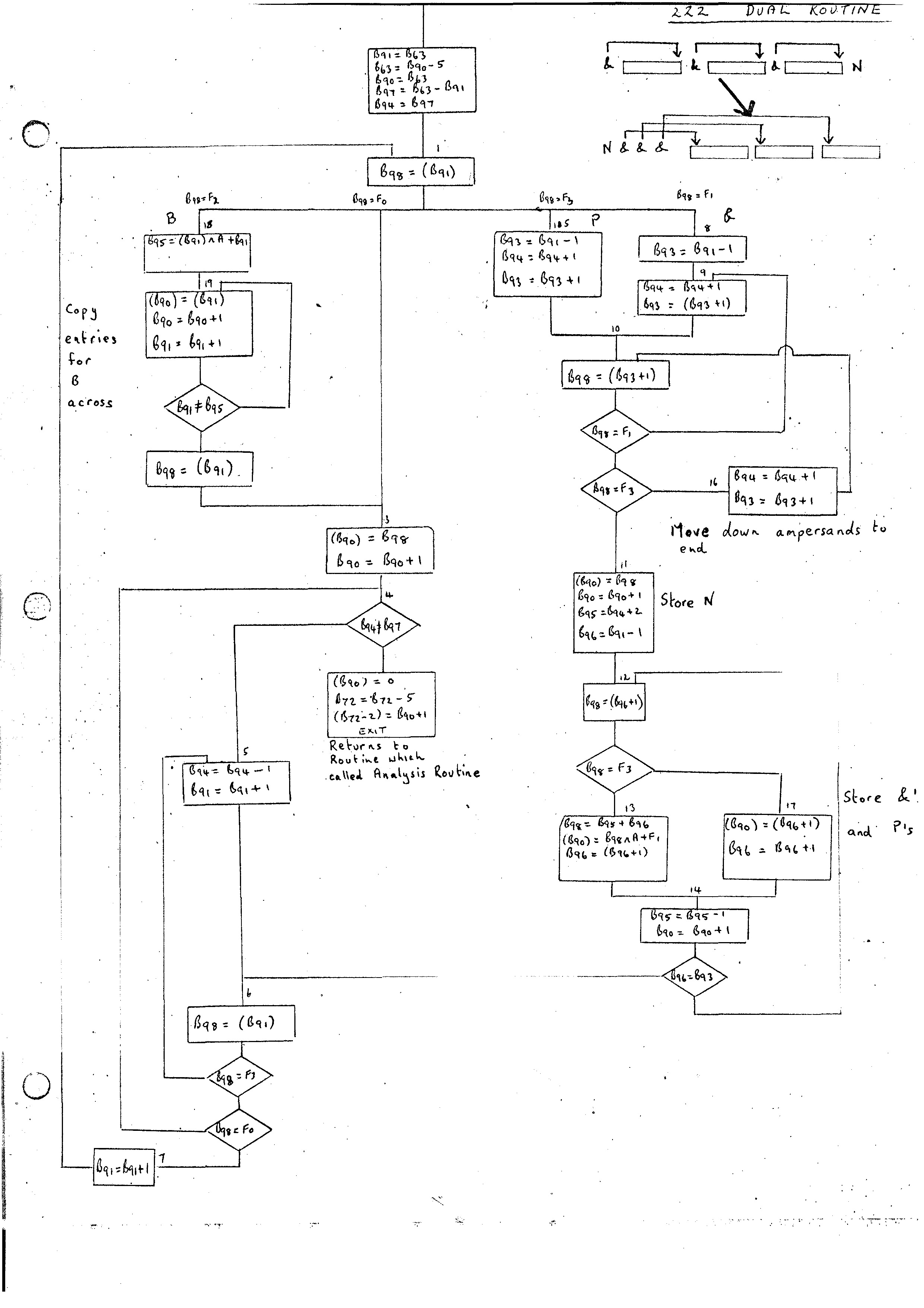
The routine 222 takes on analysis record pointed at by B63 and converts it to the Dual form. In the simple form.of analysis record we have so far it is only necessary to move the one word analysis record to the top of the stack. To speed up the return mechanism the Routine 222 first moves the stack to its position before entry to 222 so that the return on exit causes control to go right back to the Master Routine. Orders required are:-
B90 = B90-4
(B90-1) = (B63)
B63 = B90-1
(B90) = 0
B72 = B72-5
(B72-2) = B90+1
Return
The ITEM assembly routine was originally designed to compile Atlas Machine Orders. On examining the Compiler-Compiler it was found that the set of orders used corresponded very closely with the set of orders required for manipulating the B variables and with very little change it was possible to remove the Atlas dependent features. It can, therefore, be thought of as an assembler for certain macros which describe operations on the B variables.
The B variable can be thought of as being split into several fields:-
J       a 3-bit field
Z       a subsidiary address field
S       2-bit field
A       main address field
F       2-bit field.
The Z-field need not be as long as the field A and its length is one of the parameters of a particular implementation. It should be at least 7 bits in length. It will be filled by first inserting the information in the A field followed by a move order which will move it to the Z-field. The contents of the Z-field will be extracted in a similar manner.
Logic operations are provided on all fields other than the Z-field.
The syntax of an ITEM routine is as follows:-
The symbol | is used to delimit alternatives and * and ? have their Compiler-Compiler meaning.
<Item Routine> ::= ITEM <N> <EOL> <instruction * ? >
<N> ::= an integer
<EOL> ::= newline
<instruction> ::= <label ?> <un1-instruction> <EOL>
<un1-instruction> ::= <H-instr> | <C-instr> | <I-instr> | <OP-instr>
<label> ::= / <N> /
<H-instr> ::= H = <H-addr>
<H-addr> ::= <N><+JSF * ?>
<+JSF> :: = + J <N> | + S <N> | + F <N>
<C-instr> ::= C = <C>
<C> ::= possible input character
<I-instr> ::= I<N>
<OP-instr> ::= <LOGIC> | <MOVE> | <NORMAL> | <TEST> | <TRANSFER> | <OUTPUT> | <101> | <121> | <124>
<LOGIC> ::= <LOGICOP> , <BA> , 0 , <LOGICADR> | 0165, <BA> , <BM> , <LOGICADR>
<LOGICOP> ::= 0127 | 0167 | 0121
<LOGICADR> ::= <N> | F <N> | J <N> | A | M
<BA> ::= integer between 0 and 126
<MOVE> ::= <MOVEOP> , <BA> , 0 , 0
<MOVEOP> ::= 0105 | 0106 | 0163 | 0164
<NORMAL> ::= <NORMALOP > , <BA> , <BM> , <XN>
<NORMALOP> ::= 0101 | 0104 | 0107 | 0110 | 0113 | 0114 | 0121 | 0122 | 0123 | 0124 | 0145 | 0147 | 1102 | 1117 | 1166
<XN> ::= X <N> | <N>
<TEST> ::= <TESTOP> , <BA> , <BM>, <XN>
<TESTOP> ::= 0152 | 0170 | 0172
<TRANSFER> :: = <TRANSFEROP> , 127, 127, L <N>
<TRANSFEROP> ::= 0224 | 0225 | 0226 0227
<OUTPUT> ::= 1064, 0 , <BM> , 0 | 1064 ,0 0, <N> |1065 ,0,0, <N> | 1066 ,0, 0, <C>
<101> ::= 0101 , 127 , <BM>, <XN>
<121> ::= 0121, 127, 127, 1 <N> | 0121, 127, <BM> , <N> | 0121, <BA> , 127, L<N>
<124> ::= 0124 , 127 , 0 , 1 <N>
N.B. When Z,S fields are present then the A field need only be 10 bits in length.
The semantics of these instructions are:-
This sets the next store location equal to the value of the expression on the right of the equal sign.
This sets the next store location equal to the numerical number equivalent to the character defined in the address field.
This sets the index position <N> equal to the current position in the record store. It, therefore, provides a subsidiary entry point to an ITEM routine.
These correspond fairly closely to the numerically equivalent Atlas machine orders. (The <MOVEOP>'s and 1066 are different.)
In the address field we have:-
<N>    meaning the constant integer
X<N>    meaning the location of the Nth index position
F<N>    meaning F field set to N
J<N>    meaning J field set to N
A meaning address mask
M meaning mask for instruction word other than address field
The B-variable 127 on Atlas is also the location counter. The value of L<N> is the relative position of label <N> from the current position of the location counter. Therefore, 121, 127, 127, L<N> is equivalent to setting the location counter equal to its present value + the relative position of L<N> from the present value; that, jump to label <N>. Looking at it this way will perhaps show the reason for the different instructions and also some hint on how to implement them on a particular machine.
0127, i , 0 , k   sets Bi = Bi ∧ k
0167, i , 0 , k   sets Bi = Bi ∧ k
0121, i , 0 , k   sets Bi = k
0165, i , j > k   sets Bi = Bj ∧ k
0105, i , 0 , 0     Z field of Bi moved to A
0106, i , 0 , 0     A field of Bi moved to Z
0163. i , 0 , 0     S field of Bi moved to A
0164. i , 0 , 0     A field of Bi moved to S
0101, i , j , G     sets Bi = (Bj+G)
0104, i , j , G     sets Bi = Bi + (Bj+G)
0107, i , j , G     sets Bi = Bi ∧ (Bj+G)
0110, i , j , G     sets (Bj+G) = (Bj+G) - Bi
0113. i , j , G     sets (Bj+G) = Bi
0114. i , j , G     sets (Bj+G) = (Bj+G) + Bi
0121. i , j , P     sets Bi = Bj+P
0122. i , j , P     sets Bi = Bi - Bj - P
0123. i , j , P     sets Bi = - Bj - P
0124. i , j , P     sets Bi = Bi+Bj+P
0145, i , j , G     sets Bi = Bj ∧ (G)
0147, i , j , G     sets Bi = Bi ∧ (Bj+G)
1102, 70, 76, k     sets B70 to return; inserts k into store at this point
                         and jumps to DOWN-routine
1117, 0 , 0 , 0     terminates execution
1166, 67, 0 , 0     see TRANSPLANT
These instructions should be followed immediately by a <TRANSFER> instruction. They set the accumulator or some store to positive, negative or zero.
0152, i , j , G    sets accumulator = Bi - (Bj+G)
0170, i , j , P    sets accumulator = Bj + P - Bi
0172, i , j , P    sets accumulator = Bi - Bj - P
Jumps to label defined in instruction depending on accumulator value.
0224, 127, 127, Li   jump to Li if Accumulator = 0
0225, 127, 127, Li   jump to Li if Accumulator ≠ 0
0226, 127, 127, Li   jump to Li if Accumulator ≥ 0
0227, 127, 127, Li   jump to Li if Accumulator < 0
The label position is defined by inserting (i) before the required instruction. Later it will be seen that all routines must be relocatable in the record transfer. For this reason all jumps should be made either relative to the entry point of the.routine (B71) or relative to themselves.
These instructions produce output on a selected device as follows:
1064, i , j , 0    outputs character with numerical value Bj
1064. 0 , 0 , k    outputs character with numerical value k
1065. 0 , 0 , k    outputs newline (this could be extended)
1066. 0 , 0 , D    outputs character D.
This is an indirect transfer instruction
0101, 127, j , X0   transfers control to the address given by the contents of Xj
0101, 127, j , G    transfers control to the address given by the contents of Bj+G
0121, 127, 127, Lj   transfers control to Lj
0121, 127, Bj, 0     transfers control to address stored in Bj
0121, Bj, 127, Lj    sets Bi equal to address of label Lj
0124, 127, 0 , Lj transfer control to Lj
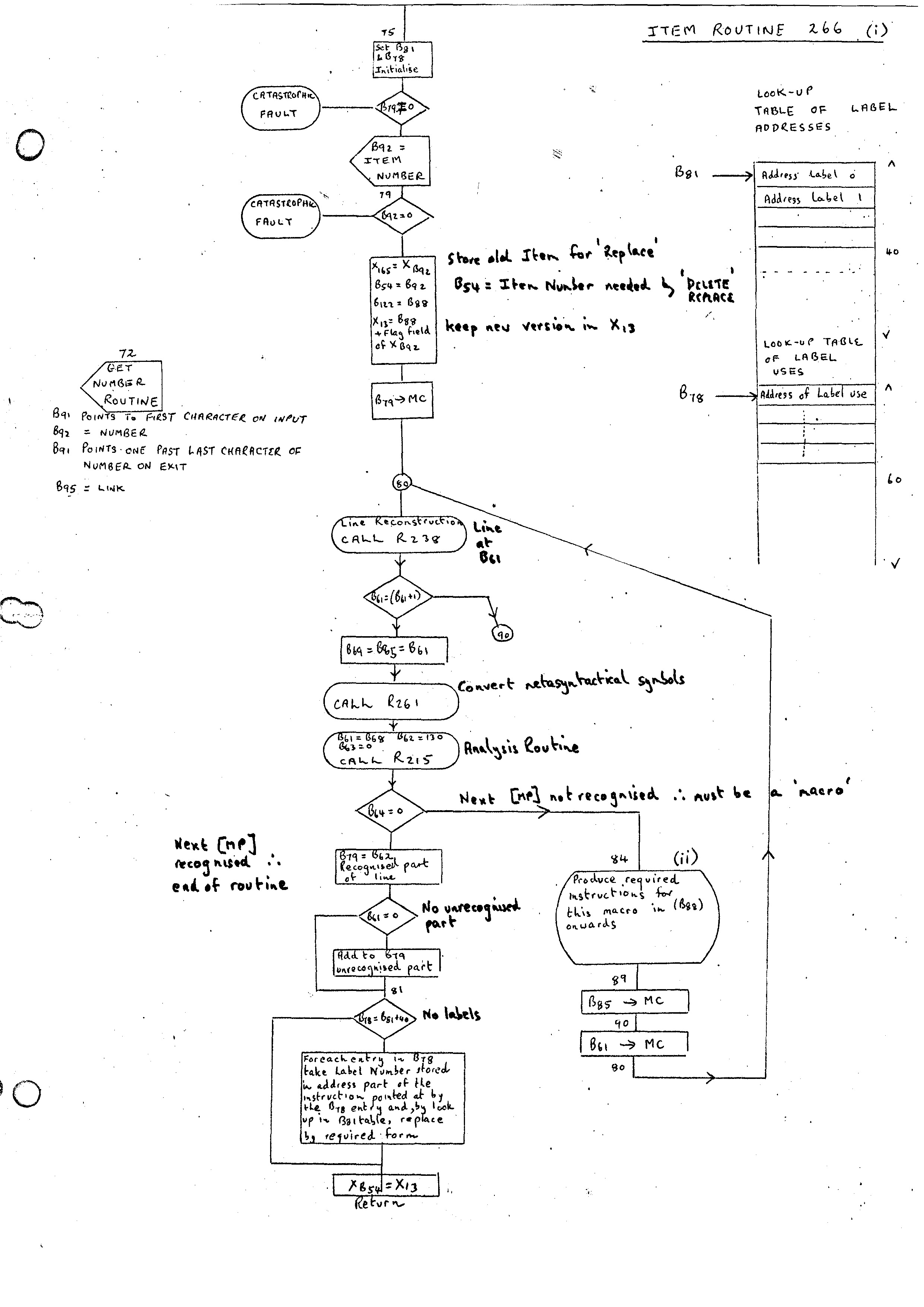
The complete action of the ITEM assembler can be described as follows:-
Although different implementations will be forced to use different methods for the assembler, it is probably worthwhile giving a broad description of the way the G-21 assembler is organized. A complete flow diagram of the routine is given in the flow charts marked ITEM ROUTINE 266 (i), (ii) and (iii).
The outer structure given above is shown on (i). To allow the DELETE ITEM routine itself to be deleted it is necessary to plant the address of the new routine in X13 initially, and only when the routine is complete will this be moved to the corresponding index position.
Two adjacent tables pointed at by B81 and B78 are required for handling labels. The first table pointed at by B81 has 40 entries corresponding to the addresses of labels 0, 1, 2, etc. The second table pointed at by B78 contains the addresses of all the instructions which referred to labels. These instructions are compiled initially with the label number in the address field. At the end of the routine this table is looked at and all the instructions have their correct address parts inserted.
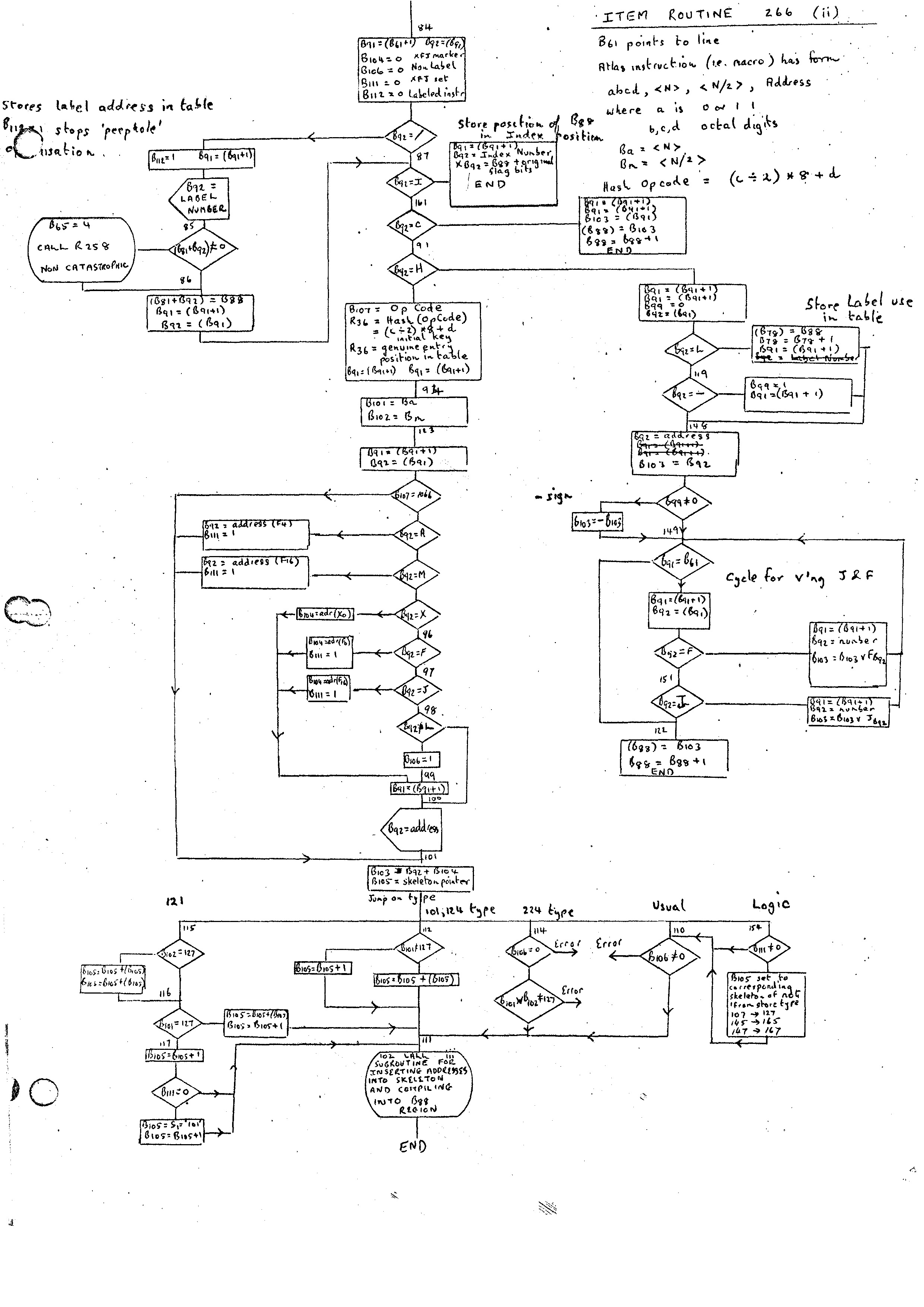
On the G-21 it was decided to store in a table code pieces for all the possible instructions macros and pick out the required skeleton depending on the instruction. There are 32 instruction opcodes, and these can be stored economically and with quick access by having a 32 entry Hash Table having as key (c/2) * 8 + d where the opcode is abcd. For example, the opcode 0152 has key 22 octal (5/2 = 2; * 8 + 2 = 22)
If two keys pointed at the same entry point then the key had 5 added to it and the process repeated.
The complete table used was:-
OP CODE       POSITION
0110            00
0101            01
1102            02
0113            03
0104            04
0105            05
0106            06
0107            07
1066            10
0121            11
0122            12
0123            13
0124            14
0225            15
0226            16
0127            17
1064            20
0224            21
0152            22
0114            23
0227            24
0145            25
1117            26
0147            27
0170            30
1065            31
0172            32
0163            33
0164            34
0165            35
1166            36
0167            37
This table then gives the position of an entry in two other tables. The first is used as a switch, depending on the type of opcode (shown as 'Jump on type' at bottom of flow diagram (ii)); the second points to the skeleton for the particular opcode.
There are basically two types of skeletons. The first is for the standard opcodes where the pointer is direct to the required skeleton. The second is for the 0101, 0124, 0121 type of instruction where the instruction may have one or more sub-forms. In this case the pointer is to a word containing the length of the first skeleton followed by that skeleton. This is repeated until we.reach the last sub-form.
Each instruction has its skeleton divided, into sub-skeletons grouped in the same way as the sub-forms are grouped. This is not necessary, as, of course, only one set of instructions is required for each opcode. However, in the cases where either the <BM> or address fields are zero, considerable economy of code may be achieved. Therefore, each skeleton is divided into four sections with the lengths preceding them:-
1. BM ≠ 0    Address ≠ 0
2. BM = 0    Address ≠ 0
3. BM ≠ 0    Address = 0
4. BM = 0    Address = 0
On the G-21 the address field of an instruction is not as large as the field of a B variable (as it is on Atlas). Consequently, several instructions have to be changed to alternative instructions when the longer field is required. For example, 0121 with a constant larger than the contents of the address field must be changed to 0101, together with the address constant stored away in an address. A typical example is:-
0121, 90, 0, Fl
which would be changed to:-
0101, 90, 0, R
where R is an address containing the constant F1.
The standard flag settings are stored in an array in the bootstrap.
It is intended that all parts special to a particular machine should be included in the bootstrap. The routines in this section at present are:-
Once the above has been written for a particular machine it should be possible to write the remainder of the Compiler Compiler in a machine independent form. The next phase is to write a set of ITEM's which will overwrite the crude versions of the routines like the Analysis Routine already defined. In general, the initial versions of the routines need not be relocatable in the Compiler Compiler form as long as the order of changing routines is in the reverse order to the one in which they were defined. For this reason the ordering of the routines given above in the Record Store should be as. follows:
1. Machine dependent routines
2. 161, 214, 261, 215, 252 and 222, in that order.
Once the Bootstrap has. been written for a particular machine all future routines added to the system can be written as ITEM routines. As stated in the previous chapter, the macro orders are in a machine independent form and so the remainder of the Compiler-Gompiler need only be written once. The ITEM routines added fall into well defined sections. Each section will produce a significant difference in the power of the system. The current section replaces the simplified form of the routines defined in the Bootstrap by their final forms and initialises the dictionaries of the system.
The Bootstrap defines two Master Phases ITEM and REPLACE ITEM and provides an analysis routine capable of recognising these two phrases and passing control to the relevant routines. These are not the only basic Master Phrases that we would like in our dictionary and our first aim will be to replace the [MP] dictionary by one containing all the Master Phrases we intend to build in. Therefore our first task is to define the REPLACE ITEM routine (164) and its subroutine 155 which deletes an item from the store. . Routine 155 has one parameter B61 which is the number of the routine requiring deletion.
The action of the REPLACE ITEM routine is straightforward. It first calls the ITEM routine which will compile the new copy of the relevant routine and store the old entry point in X165. This can then be deleted by calling 155 with B61 set to 165.
In general execution would then continue by the REPLACE ITEM routine returning .control to the Master Routine which would look for the next Master Phrase. However if the Master Routine itself has been replaced we would be returning to the deleted old version of the routine. Therefore this special case has to be tested for, in which case the END OF MESSAGE routine is called to reinitialise the compiler.
The routine 155 will delete the routine at index position B61 and return with the length of the deleted routine in B62. As the code used in the routines of the Compiler-Compiler are relocatable without alteration it is only necessary to move routines down over the space left by the deleted routine and alter the relevant Index positions. The only complication is due to the routine 155 itself being one of the routines that may need moving. The action of the routine is as follows:-
The new [MP] dictionary will also define a Master Phrase:-
DELETE ITEM
This routine will set B61 to the routine number and enter 155 to delete this routine.
A complete description of the structure of dictionaries in the Compiler-Compiler is given in the paper Trees and Routines . The dictionaries are able to reside either in the Record Store or the Chain Store. The most commonly used dictionaries tend to be left in the Chain Store, while the remainder reside in the Record.Store until alterations are required in which case they are moved to the Chain Store. The Analysis Routine is capable of analysing input with respect to dictionaries stored in either the Record or Chain Store. However some routines expect to find dictionaries in one or other of the stores and it is necessary for the Master Routine to ensure that the dictionaries are in their correct positions. Two supervisory lists are therefore provided which point to the dictionaries which are required to be moved:-
1. CONVENTIONAL LIST OF FORMAT CLASSES 129
This contains a list of the standard format classes MP, AS, BS and SS provided by the system. This can be extended by the user.
2. LIST OF ADDITIONAL DICTIONARIES TO BE PACKED 169
This is initialised to contain the Class Identifier Dictionary, (CID) 134 and the Double Entry List, 256 which stores the Compile versions of routines.
The Master Routine therefore moves all the dictionaries referenced by 129 and 169 to and from the Chain Store automatically.
Copies of all these dictionaries must be provided therefore before the final form of the Master Routine is added. The BS, AS and SS dictionaries are initialised to empty as is the Double Entry List 256.
We now have the routines required to allow us to replace the original form of the [MP] dictionary and the new version contains the following Master Phrases:-
PHRASE           218
ITEM             266
END OF MESSAGE   227
FORMAT           220
FORMAT CLASS     272
DELETE ITEM      145
REPLACE ITEM     164
DEFINE COMPILER  275
LIST             284
DO NOT LIST      285
The CID Dictionary is initialized to contain the following class identifiers:-
AS               132
ABN              154
AB               153
A                166
BS               131
B                167
PI               181
EOL                4
SS               133
SP                65
SEP              179
GENERATED-P      186
RESOLVED-P       185
LABEL            184
N                149
COMMA            229
0-3              178  (Probably redundant)
,                 10
ERAZE            127
FD               251
[                 81
OW               173
MP               130
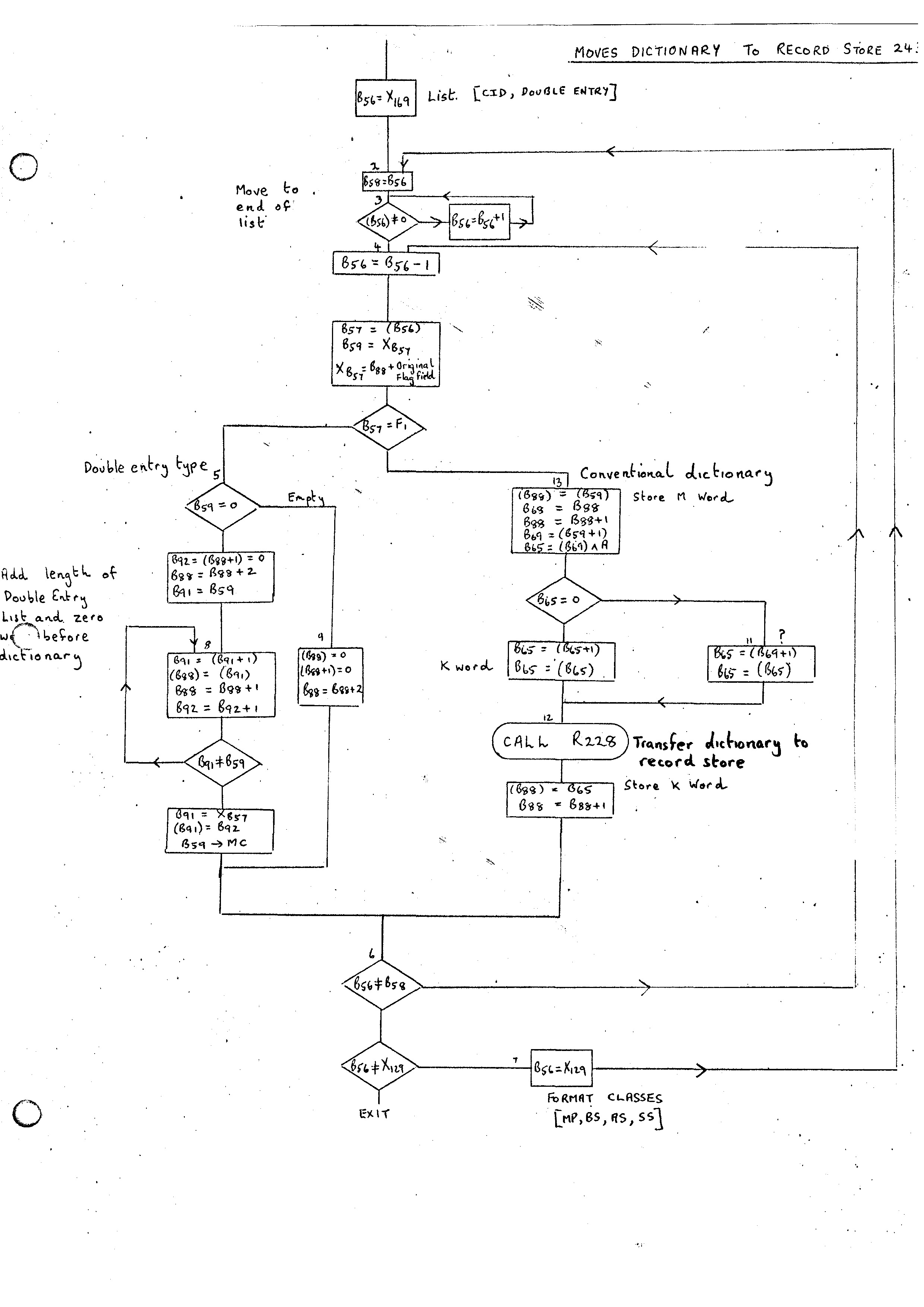
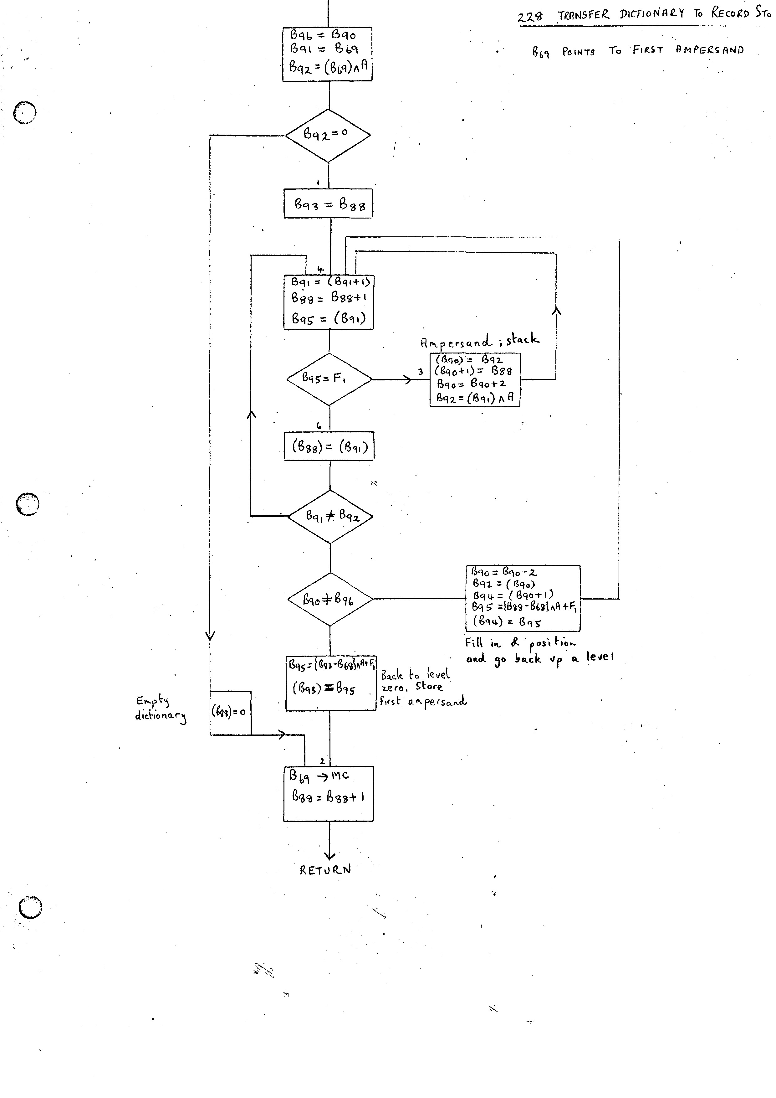
The routine 243 is added which will pack all the routines defined in the two lists described above into the Record Store. It uses a subroutine 228 which transfers an individual dictionary to the Record Store. The routine 245 and its subroutine 231 do the reverse operation.
The standard form of a dictionary in the Record Store is:-
M &......... I K
where the dotted interior is described in Trees and Routines with the ampersands pointing at the category numbers. The keywords described in Trees and Routines were not implemented. Instead a single K word giving the maximum number of ampersands on the top level of any alternative is added at the end. We have a similar form in the Chain Store with the Index entry pointing at the M word and the link from the K word pointing back to the M word.
The subroutine 231 is entered with B69 pointing at the initial ampersand and B68 at the M word. It will convert all information between and including the outer ampersand and I word to chain form with B67 pointing at the ampersand on return. In addition B66 is left pointing at the K word. The routine 245 works through all the dictionaries in both lists; filling in the M and K words itself. The action for a Double entry list is different. This conversion is done entirely by 245. In the record store the first entry of the dictionary contains length of list followed by a word containing 0 and then the words of the dictionary. In the Chain Store only the words of the dictionary appear with the Index position pointing at the last word.
The action of 243 and 228 is similar but provides the reverse operation. The flow diagrams in the appendix (243, 228) give the details of these routines.
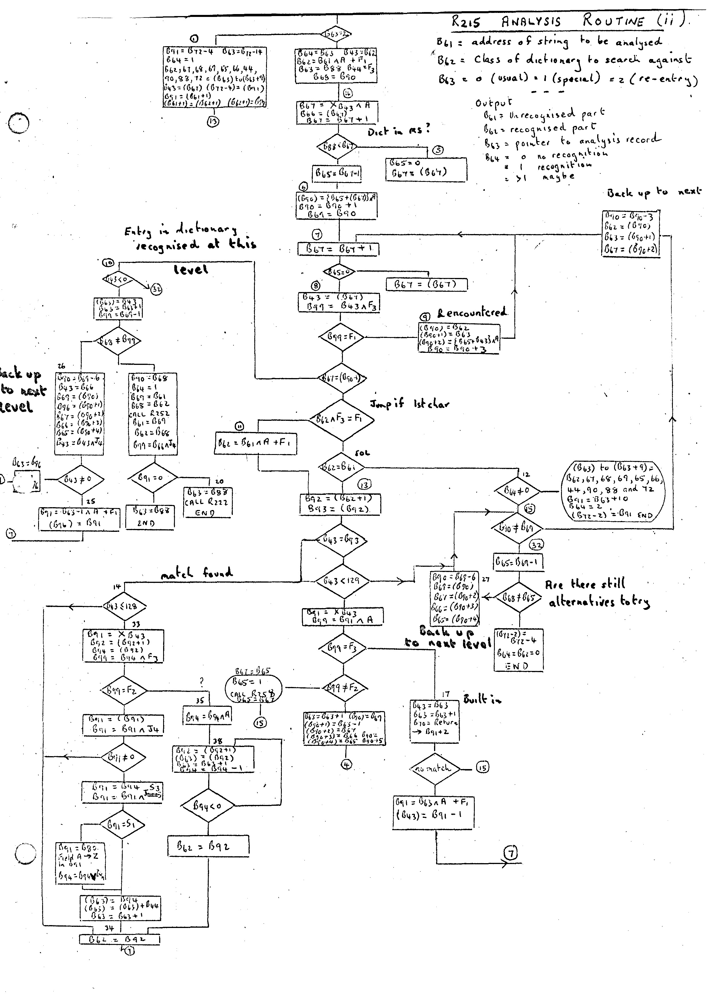
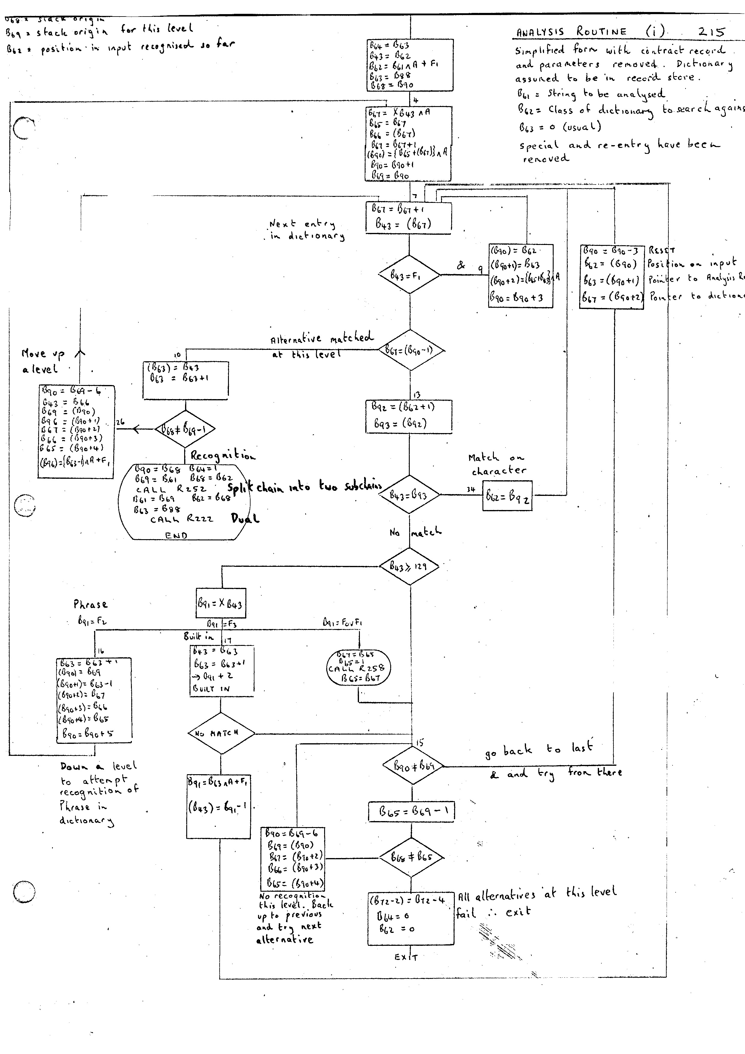
The Analysis Routine 215 is the central routine of the Compiler and provides all the mechanism for the syntactic scan. In the appendix are two flow diagrams. One gives a complete description of the routine while the second gives a simplified form of the routine showing only the main flow. Its purpose is to analyse a string of characters with respect to some class of phrase or dictionary and produce on recognition an analysis record showing how the scan proceeded.
The input parameters to the routine are:-
B61 = address of string to be analysed. This must be in the form of a circular chain with B61 pointing to the last word.
B62 = class number with respect to which the analysis is to take place. The dictionary or phrase may be either in the Record or Chain Store.
B63 = 0 for usual entry
B63 = 1 for a special entry
B63 = 2 for re-entry x
In its use during the bootstrapping of the compiler, the special and re-entry modes are not used. Consequently discussion of these will be left until later.
In the case of a Phrase being defined as Contract Record, the analysis record is deleted. This will be used when the analysis record contains no useful information. In the dictionary this is signified by the M word having the J4 bit set. All tests on J4 deal with contracting out records in the routine.
Another section of the Analysis Routine which can be discussed later in more detail is that involving parameters. It is possible that when we are reading in genuine Compiler-Compiler routines that the input stream may contain phrase identifiers. The section dealing with this (bottom left of flowdiagram (ii)) can be left for the time being.
Looking at the simplified flowdiagram (i), the main paths are as follows:-
A flow diagram for the Dual routine is given in the appendix. A complete description of analysis records is given in Trees and Routines.
The Analysis Routine and most other routines of the system on recognition of fault conditions enter one of the two fault routines. If some kind of recovery is possible from the error then Routine 258 is entered otherwise 259.
Both routines require a fault number to be set in B65. The action of these routines is mainly up to the implementation. The fault number together with the routine number (B75) give a good indication of the fault. Additional information that could be printed would be the contents of the B variables, the stack and other parts of the Record and Chain Store as desired.
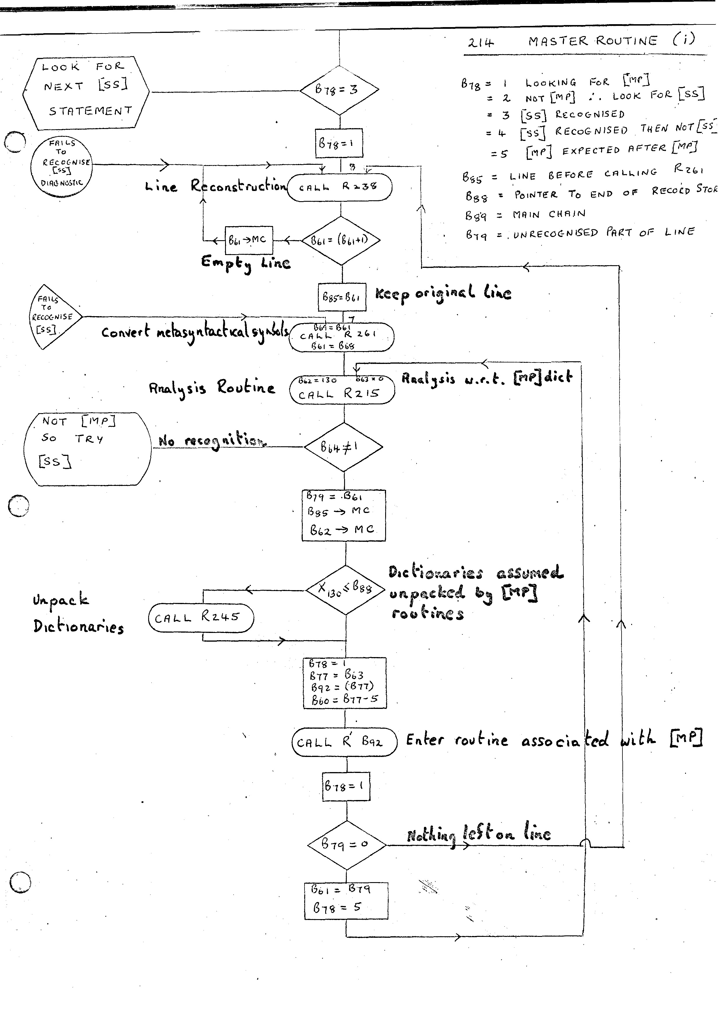
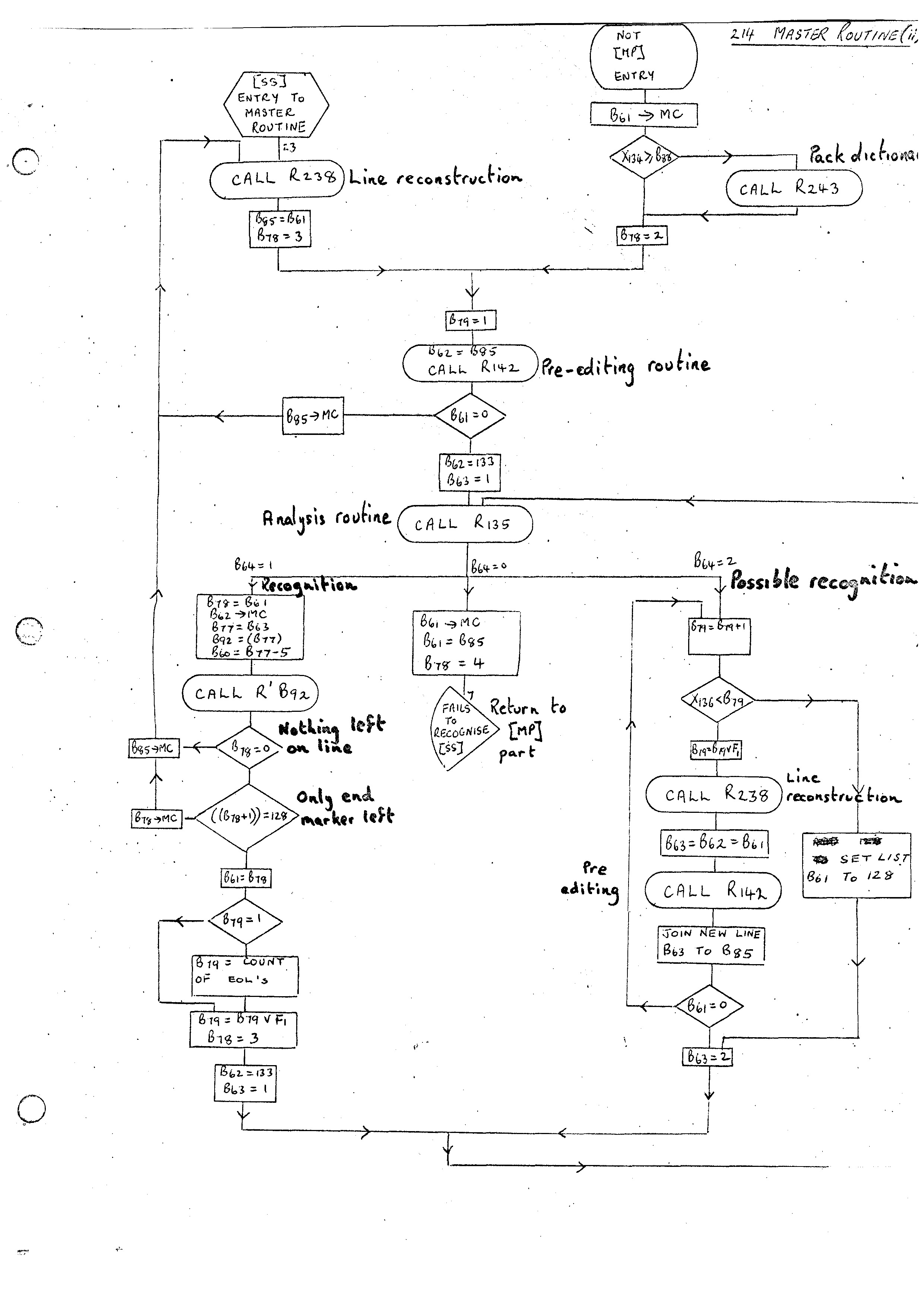
The Master Routine provides the implicit control structure of the Compiler-Compiler. There are instructions available in the Compiler-Compiler which allows the user to override the implicit control but, until these have been implemented, all control on the global level is provided by the Master Routine. This can be expressed briefly as follows:-
Safeguards are of course added to make sure that we do not get into an infinite loop. The Master Routine (i) flow diagram shows the flow for steps 1 and 2 above. Note that the line of input has a sub-scan by Routine 261 before entering the Analysis Routine. This is mainly for the removal of spaces and the setting of unique basic symbols for the meta-syntactic symbols [ and ,. On Atlas different input forms used different representations for the open bracket and it was helpful to have a unique form being passed around. On the G21 these have still been given unique values although I am still not clear how necessary this is now. The second main point is that some routines called on recognition of Master Phrases assume that the dictionaries reside in the Chain Store and so these dictionaries must be put there (if not already there) before entering routine.
The Master Routine (ii) flow diagram gives the flow for steps 3 and 4 above. This is very similar to the flow for recognition of Master Phrases. A separate sub-scan routine 142 is provided and the input is passed through this before calling the analysis routine 135. Routine 135 is basically identical to Routine 215. On Atlas it is compiled in a non-relocatable form for efficiency purposes and also produces the Dual form of the analysis record directly. (This is the reason for the K word on dictionaries.)
The other main difference between the two flows is that there is an assumption that the Master Phrase can be recognised with the available input. In the flow for Source Statements it is possible to get a maybe recognition which will reenter the Analysis Routine after processing further input. The Routine 135 on Atlas will only analyse with respect to dictionaries in the Record Store (again for efficiency). Consequently dictionaries must be packed into Record Store the first time we look for a Source Statement.
A little care must be taken when replacing the Master Routine. As stated before the REPLACE ITEM routine will call the END OF MESSAGE routine in this case. Just before replacing the Master Routine, an interim version of the END OF MESSAGE routine is added. This reenters the Master Routine as though it had been called from Routine 150. Once the Master Routine has been replaced the final version of END OF MESSAGE is added. This packs up dictionaries into the Record Store. This was not required originally as the unpacking had not been done by the original Master Routine due to Routine 245 being replaced by a dummy.
The next aim is to add the routines necessary for compiling the PHRASE statement. Basically all that is required is the PHRASE routine, associated with the Master Phrase:-
PHRASE 218
This, however, requires quite a large number of subroutines which can be divided into basically two classes. The first set consists of general subroutines for dictionary manipulation and printing which will be equally useful later on. The second set consists of routines, dictionaries and syntax definitions closely associated with the PHRASE statement.
The complete set of routines required are as follows:-
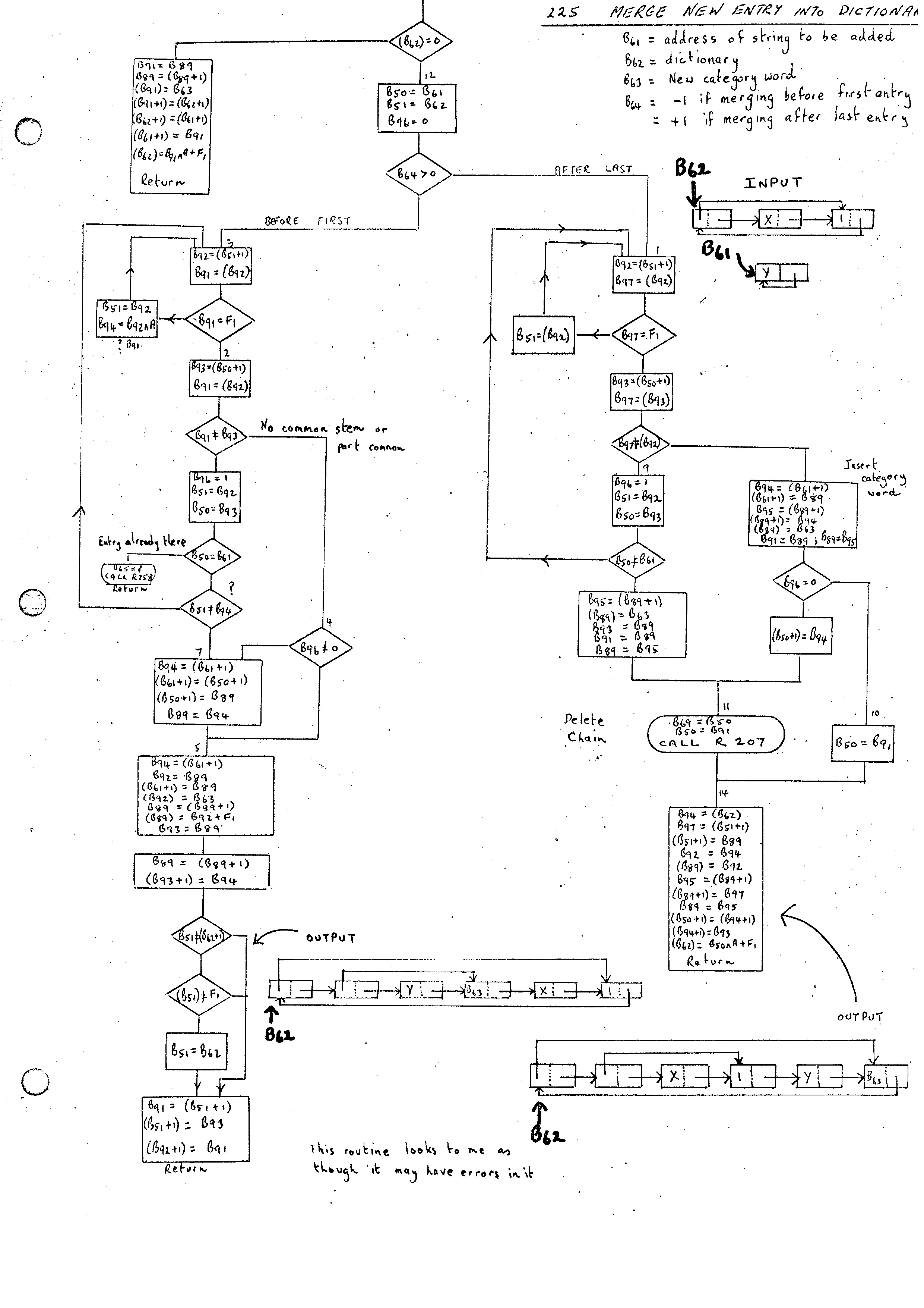
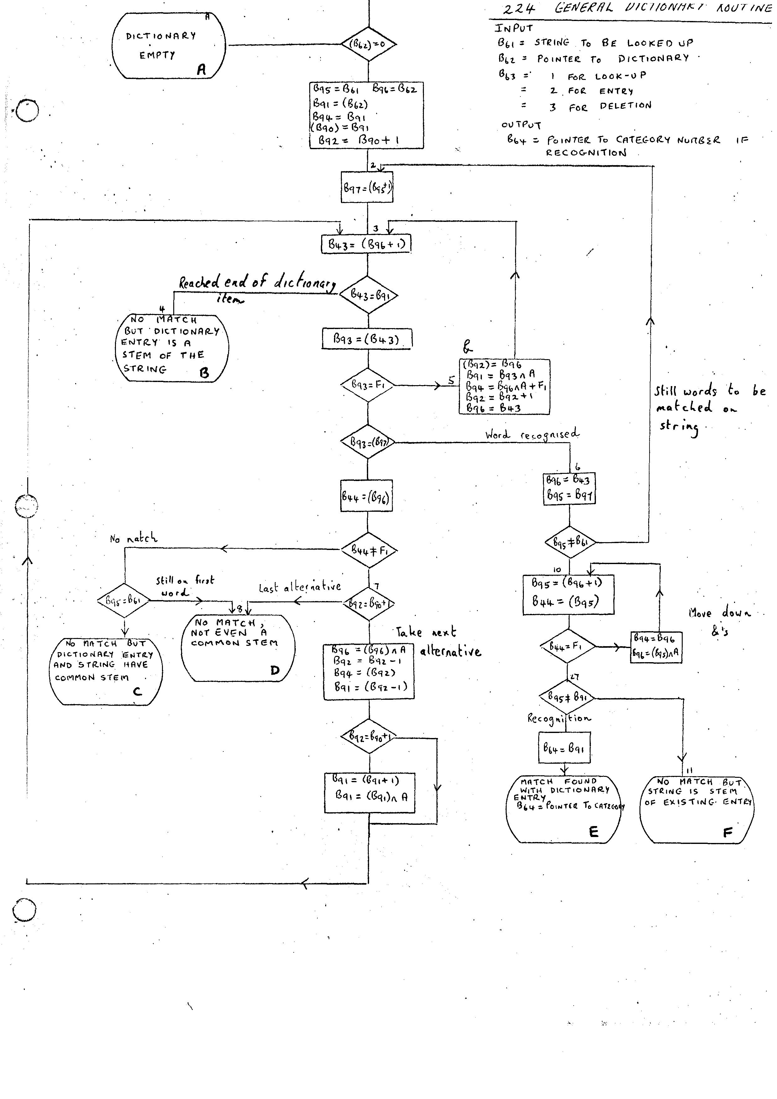
204  Add word to list
205  Add word to nest
206  Withdraw word from nest
207  Delete list
209  Add list to list
210  Copy linear list to chain
259  Add nil branch to dictionary
141  Look up or enter in a double entry dictionary
225  Merge new entry into dictionary
224  General dictionary routine
Pictorial descriptions of all these routines apart from the last two are included in the appendix.
Routine 225 can be used to add an entry to the front of a dictionary or alternatively at the end. Its flow diagram is given in the appendix.
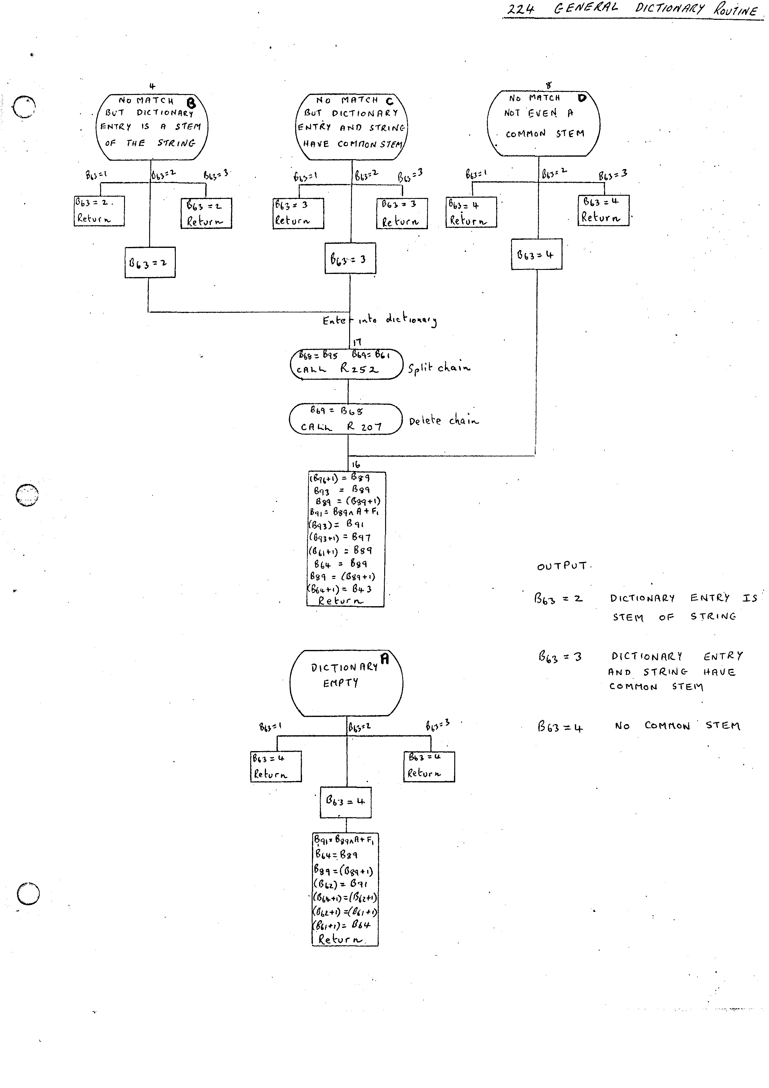
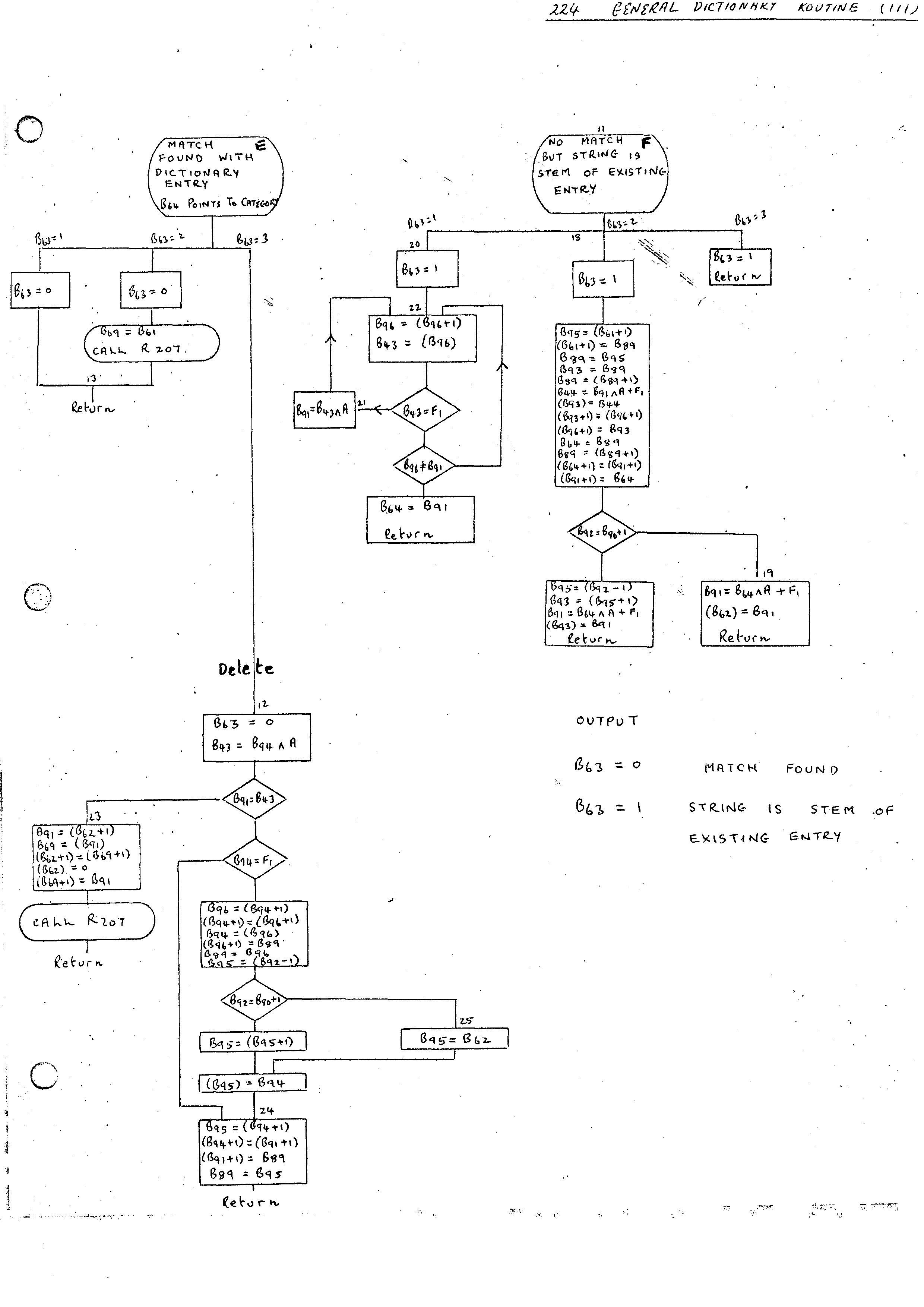
The General Dictionary Routine 224 has three main purposes. To lookup, enter or delete entries from a dictionary. The flow diagram (i) gives the outline of the parts of the routine common to all three types of entry. Flow diagrams (ii) and (iii) give the parts which depend on the types of entries. The first part differentiates between the following 6 cases:-
The action required then differs depending on whether look-up (B63 = 1), entry (B63 = 2) or deletion (B63 = 3) is taking place.
The philosophy adopted in the Compiler Compiler, as far as interface with the sub-scan and initial input is concerned, is to take all the input required for a particular statement and then to process the statement independent of further access to the sub-scan level. This is obviously inefficient as far as storage use is concerned unless the amounts of storage required in this way are small and this need not be the case. In the case of the Phrase Statement this, however, is usually so and is probably the simplest and most efficient method of execution.
Two routines are required to read in the whole of the Phrase Statement.
1.  READ NEXT  SECTION          213
2.  DELETE  SUPERFLUOUS EOL'S   265
The .first routine reads in statements until it reaches a line that can be recognized as the next Master Phrase by the Analysis Routine. All the input up to the next Master Phrase is read and built up into a list pointed at by B61. The next Master Phrase is pointed at by B79. Both strings are stored as conventional circular chains. The B61 chain has a character 128 added at the end.
The second routine removes all redundant end-of-line characters which may have been inserted during the process of building-up the body of the Phrase Statement.
Once these two routines have been accessed, the Phrase Statement body in B61 is ready for analysis.
The only input to Routine 213 is the variable B79 pointing at the first line of the Phrase Statement with the characters P, H, R, A, S, E removed.
The Routine 265 enters with B69 pointing at the input to be checked. On exist B69 points to the reduced line.
The two routines required are:-
177    PRINT NEW FORMAT OR PHRASE
183    PRINT SYMBOL
The first routine will output the words from B68 until B69. Each word is output as a symbol if it has a value less than 128 else the number itself is output surrounded by square brackets. This is followed by the Phrase or Format Index Number which is passed as a parameter stored in B67.
The Routine 183 is a subroutine which prints the value of B69 as a symbol.
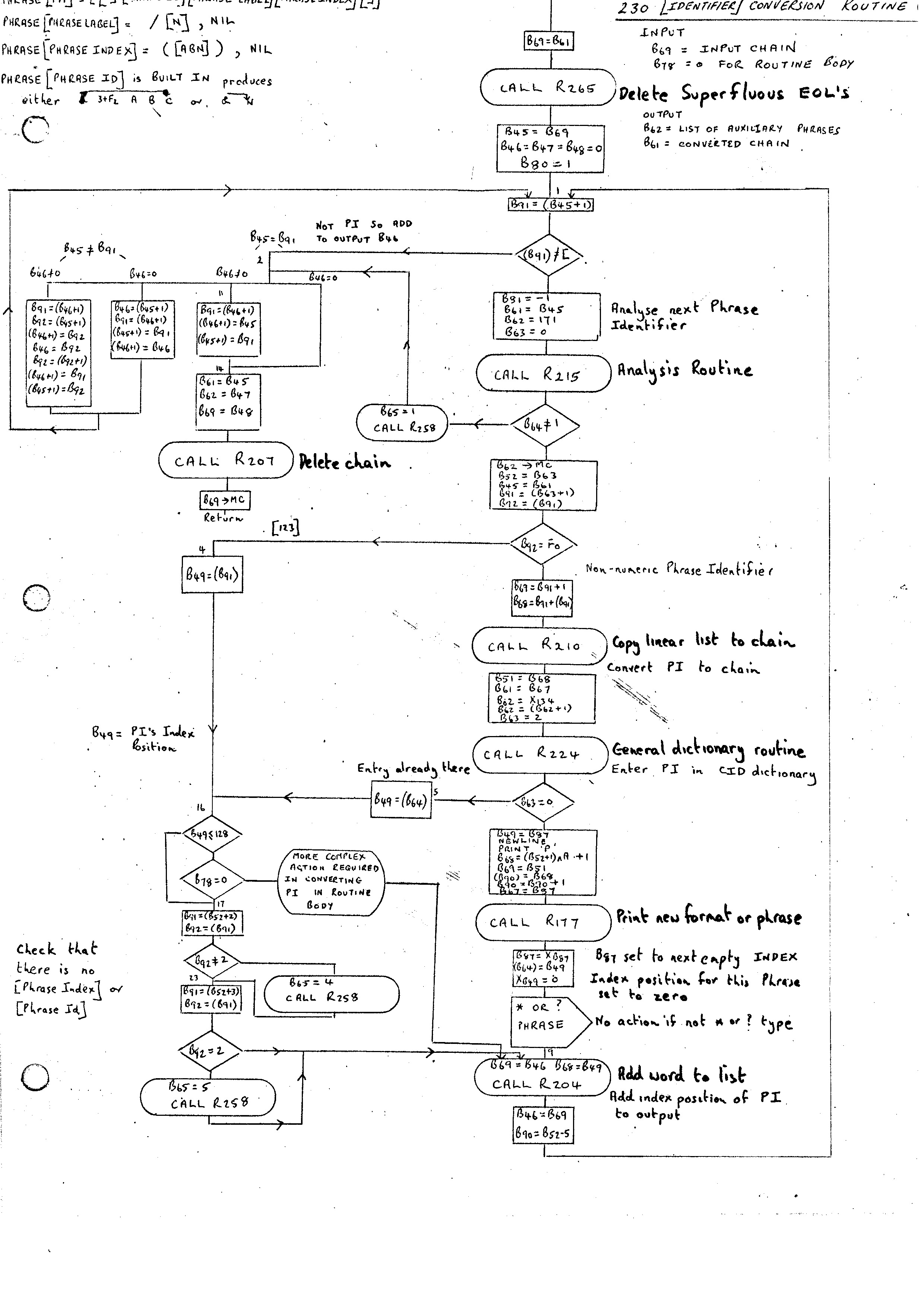
The first action of the Phrase Routine, after the complete statement has been input by Routine 213, is to call the Identifier Conversion Routine 230.
Routine 230 is also used by the ROUTINE routine for reducing the body of a routine and, for this purpose, it has to recognize and separate different phrase variables of the same type. In the case of the Phrase Routine entry (differentiated by B78 being non-zero) it has the task of replacing each Phrase Identifier enclosed in square brackets by its position in the index. Characters other than Phrase Identifiers are not changed.
At this point we see the first use of the Analysis Routine as an internal recognizer. This routine has been designed to analyze strings with syntactic structure. The generalized phrase variable falls into this category. As we have not yet implemented the PHRASE statement for defining syntactic structure the syntax has to be built in as ITEM's. The phrase variable can then be checked by the analysis routine for legality. The syntax of the PHRASE variable is as follows:-
PHRASE [PHRASE VAR]   = [[][PHRASE ID] [PHRASE LABEL] [PHRASE INDEX] ]
PHRASE [PHRASE LABEL] = / [N] , NIL
PHRASE [PHRASE INDEX] =  (  [ABN]  ) , NIL
The [PHRASE ID] recognizer is a Built-in Phrase. This means that instead of a conventional dictionary form of entry used by the Analysis Routine to test for recognition, we have a subroutine which itself looks at the input stream and, if it recognizes anything, will produce an analysis tree. Built-in Phrases will, in general, be used when efficient recognition can be done by this non-standard method. The [PHRASE ID] routine has to recognize two basically different kinds of Phrase Identifier. The commonest will be an open square bracket followed by a set of characters terminating with a close square bracket. The second form is open square bracket, integer, close square bracket. This will be used if, for example, a dictionary or phrase has been put in as an ITEM and has no name entered in the CID dictionary. In this case the integer represents the index position.
If, for example, we have the Phrase Identifier [ABC] then the analysis tree produced will be
& 3+F2 A B C
with the ampersand pointing to C. The word containing an F2 flag bit is a Block Word (see Trees and Routines), which indicates that the next 3 characters should be treated as a string and not processed by routines which manipulate analysis records.
The second form of Phrase Identifier [175], for example, produces an analysis record
& N
where N = !75. The differentiation between the two forms is done by noting whether or not the Block Word is present.
The Index Positions of the above Phrases are:-
171 PHRASE VAR     -      '                      -
172 PHRASE ID
174 PHRASE LABEL
176 PHRASE INDEX
Once the call on the Analysis Routine by Routine 230 has produced a recognition then there are two main paths. If the Phrase Identifier is a simple index position then all that is required is to add this value to the output stream and continue.
If we have a genuine Phrase Identifier, it must be looked up in the CID dictionary. If it is already there then its index position is obtained and proceed as above. If not there, then we must assign an index position to this identifier and add it to the CID dictionary. A record of where this Phrase Identifier has been put is printed, its index position cleared and then proceed as before.
The one complication to the straightforward process defined above is the introduction of * and ? endings to Phrase-Identifiers which generate additional Phrase declarations. For example, [ABC *] appearing anywhere implies an additional Phrase declaration
PHRASE [ABC *] = [ABC] [ABC *], [ABC]
Similarly, [ABC ?] implies an additional Phrase declaration:-
PHRASE [ABC ?] = [ABC] , NIL
In the case of a new Phrase Identifier with either ending appearing it is therefore necessary to also insert an entry in CID and assign an index position for the Phrase Identifier without the ending.
Also, the above definitions must somehow be added to the Phrase Definitions presented to the PHRASE routine. This is done by building up a bit of additional Phrase Statements that are generated in this way and then processing these before the Phrase statement we were processing originally. Skeletons for the two types of Phrase definitions to be added are stored in ITEM 139. Processing is done by the call of the Auxiliary Phrase Routine 242.
Once the Identifier Conversion Routine 230 has reduced the Phrase Identifiers to their associated numeric values we can process the Phrase Statement body. Once again the Analysis Routine is used to produce the recognition. The built in syntax is as follows:-
PHRASE [PHRASE BODY]        = [CONTRACT RECORD] [ANY PHRASE ID] = [PHRASE TAIL]
PHRASE [CONTRACT RECORD]    = (C R) , NIL
PHRASE [PHRASE TAIL]        = [PHRASE ALTERNATIVE] [PHRASE TAIL] , [PHRASE ALTERNATIVE] [128]
PHRASE [PHRASE ALTERNATIVE] = BUT NOT , [PHRASE ELEMENT] [,] , NIL , [PHRASE ELEMENT]
PHRASE [ANY PHRASE ID] is built-in and just checks for a Phrase Identifier in the next position of the input. The Analysis Record .produced being
& N
PHRASE [PHRASE ELEMENT] is built-in and checks for a sequence of Phrase Identifiers or basic characters terminating on [,] or [128], The analysis record produced for a string of N such symbols is
N+F2 C0 C1 ... CNN
where the Ci are the characters checked.
The positions of these phrases is as follows:-
PHRASE  BODY       151
CONTRACT RECORD    143
PHRASE TAIL       156
PHRASE ALTERNATIVE 157
ANY PHRASE ID      152
PHRASE ELEMENT     158
The remainder of the Phrase Routine consists of building up the Phrase Entry from the sub parts detected by the Analysis Routine using the routines for adding entries to dictionary. The BUT NOT entry has to be added before the first entry, otherwise the process is straightforward. The Contract Record Phrase will have the T4 bit set in the M word. The K word contains the maximum number of phrase identifiers in any alternative.
These 3 routines are required to recognize the basic variables and constants of the system. They are built-in for efficiency purposes. Although only [N] has been used so far in a positive manner the other two have been used to ensure that a Phrase Index- does not appear. It is not essential to add [ABN], [AB], [A] and [B] at this stage, but the routines for [N], [A] and [B] are coded as a single routine with multiple entry points and will, therefore, all be treated now.
In the case of [N] recognition is successful if an integer with less than 9 digits appears. The analysis record consists of just the integer value. The anlaysis record for [B] is exactly the same. Once the B has been checked, the [N] routine is entered.
[A] is recognized in a similar way, although, the analysis tree produced is different. In this case we have to reset B81 to the maximum value of [A] encountered, so far. The Analysis Record in this case consists of two words. The first contains 1*J4+F2 and the second B80 + i for Ai.
B80 by this time will have the number of Phrase Identifiers appearing in.a particular routine so that B80 + i will be the position of Ai in the LSE (List of Selected Expressions). On. execution, the address of Ai is the value in the Analysis Record relative to B72.
Once the above has been written it will be possible to add Phrase Statements to the Compiler Compiler. Although none will be required at this point it is a convenient point to stop and test before proceeding. The actual definition of Phrases and Formats is not really necessary until after we have introduced the ROUTINE routine.
The FORMAT statement defines an additional statement to be added to one of the defined classes. A Format Class Dictionary can be thought of as an extendable PHRASE dictionary. In place of all alternatives having to be defined together, we are able to define alternatives as they are required. Due to this similarity the routines required for the implementation of the FORMAT statement are the same as those required for the implementation of the PHRASE statement.
The Master Routine recognizes the phrase FORMAT and enters the Format Routine (213). This reads in the whole of the Format Statement, converts the Phrase Identifiers using Routine 230 and analyzes the statement with respect to the following built in syntax.
PHRASE [FORMAT BODY] = [PI] = [FORMAT PHRASE] [SERIAL NO] [EOS]
where
PHRASE [SERIAL NO] = [,] [N] , [,] [158] , NIL
and
152   PI
158   FORMAT PHRASE
These two Phrases have been used in compiling the PHRASE statement. The second alternative to the [SERIAL NO] is not documented as far as I can see and probably not implemented. Once the Analysis has been completed correctly, a check is made that the Format Class Dictionary to be altered is in the Chain Store.
If a Serial Number is given, then this is allocated to the Format Routine. If not, then the next free position in the INDEX is allocated.
A count is made of the number of Phrase Identifiers in the FORMAT and this is compared with the last word of the dictionary which is always adjusted to contain the maximum number of Phrase Identifiers +1 in any Format.
As for the Phrase Statement, the routine 225 is used to merge the new entry into the dictionary.
So far the implementation has been primarily concerned with the syntactic analysis of statements. The ROUTINE statement provides the means for defining the semantics associated with a particular statement. Once this has been incorporated together with some Basic Statements, the compiler will be in its minimum workable form. Once this point has been reached, extension of the Compiler can be achieved by using its own definitional facilities.
A CC ROUTINE can be divided into two parts: the heading followed by the body. The main purpose of the heading is to define to which Index position this routine is to be attached. This can be done by either specifying the Index position or providing a heading which can be matched against a FORMAT already defined. In this second method parameters can be specified as input parameters to the ROUTINE. In the FORMAT statement for a particular instruction will be Phrase Identifiers which define the syntactic phrases expected at certain points in the FORMAT. In the ROUTINE heading, Phrase Variables will appear at positions corresponding to the Phrase Identifiers in the FORMAT statement. When a particular statement of this type is recognized, then the Phrase Variables in the Routine heading will be given as values in the analysis trees produced during the recognition of the associated Phrase Identifiers in the FORMAT.
The FORMAT statement, therefore, defines the types of phrases expected while the ROUTINE heading states which Phrase Variables are assigned the analysis tree values when a particular statement is recognized.
The ROUTINE body consists of statements in any of the three Format classes:- BS, AS and SS. To initialize the bootstrapping process some basic statements must, of course, be provided external to the general system. These are the BASIC STATEMENTS to be defined as ITEM routines which will be described later.
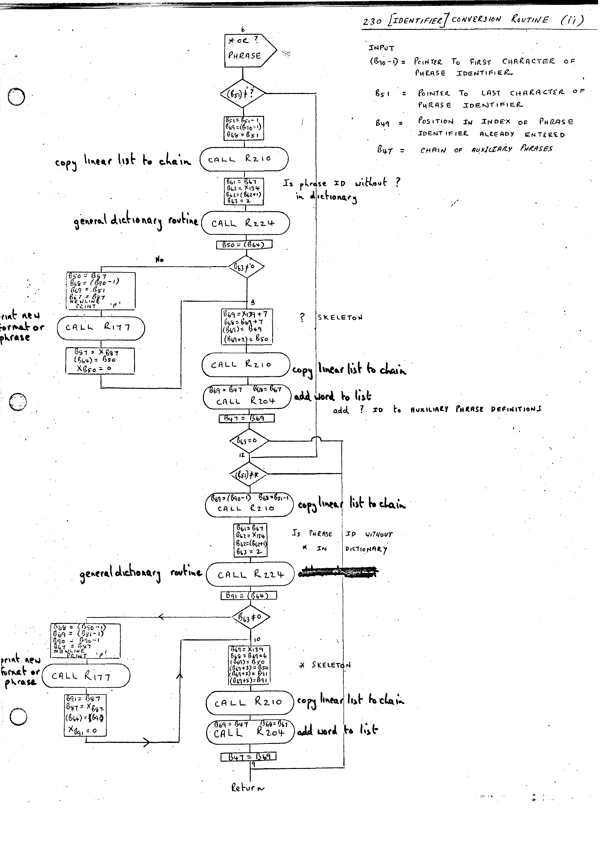
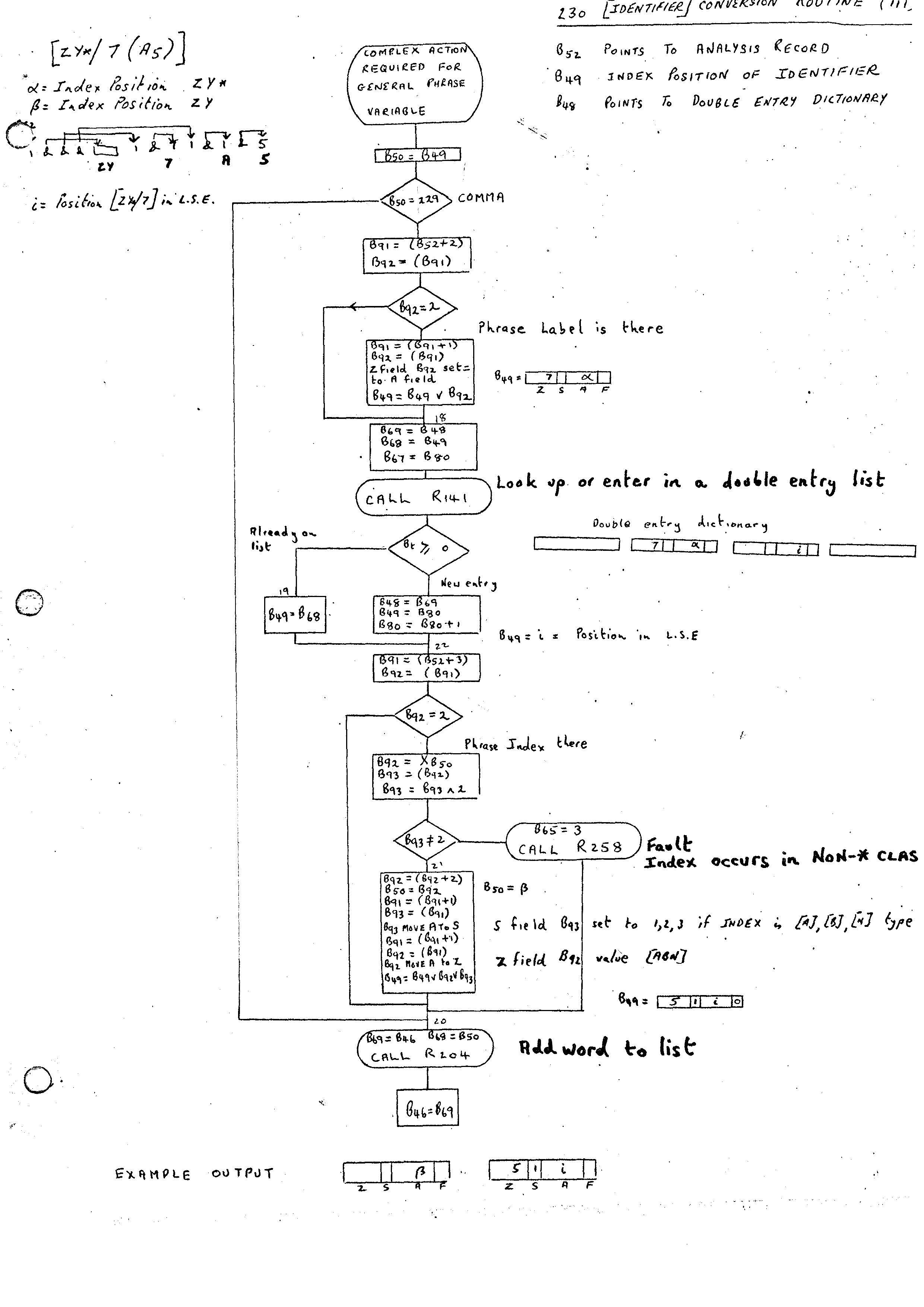
Like the PHRASE and FORMAT statements, the whole of the ROUTINE is input initially, and the Phrase Variables are converted using the Identifier Conversion Routine 230 (flow diagrams (i), (ii), (iii)). In the case of the ROUTINE statement Phrase Variables rather than Identifiers appear. These may have labels and indices attached, and the output from the routine is more complex than the Index Position produced in the case of the PHRASE and FORMAT statements. This alternative path is marked by B78 being set to zero on entry. The additional part of the Identifier Conversion Routine is given in flow diagram (iii).
The output for each Phrase Variable is now as follows:-
For example, the Phrase Variable [ZY*/7(A5)] where
a = Index Position [ZY*]
b = Index Position [ZY]
i = Position of [ZY*/7] in L.S.E.
would produce as output:-
1.  A field set to b
2.  A field set to i
    Z field set to 5
    S field set to 1
A Phrase Variable without a label is assumed to have a label value of zero.
The Routine Heading is recognized by the Analysis Routine where the built-in syntax can be described as follows:-
PHRASE [ROUTINE HEADING] = SMALL R [N], R [N], [COMPILE] [PI] [EQV] [RESOLVED-P]
PHRASE [COMPILE]         = (COMPILER), 'NIL
PHRASE [RESOLVED-P]      = [SET P'] [ANY PI] [RESET P]
The Index Positions associated with these are as follows:-
254 ROUTINE HEADING
249 COMPILE.
181 PI
185 RESOLVED-P
152 ANY PI
244 SET P'
250 RESET P
The first two alternatives are straightforward.
The SMALL Routine is defined as one which only needs the simple form of entry mechanism and cannot have statements in its body which cannot be compiled. It is entered using the simplified non-stacking entry via the DOWN routine.
The [COMPILE] option, if present, states that this version of the routine is designed to produce compiled code for the statement rather than interpret the Analysis Record. More will be said of COMPILE routines later.
The phrase [PI] is built-in and will recognize any Phrase Identifier. Its action is given in the flow diagram. Note that it modifies the syntax for [GENERATED-P] and also [RESOLVED-P]. The latter modification changes [ANY PI] to the particular Phrase Identifier recognized by [PI]. This ensures that the analysis depends on the initial [PI]; that is the remainder of the heading is analyzed with respect to this Format Class.
Once the ROUTINE heading has been recognized a check is made that a match at the top level between the Phrase Identifiers appearing in the Format and the Phrase Variables appearing in the ROUTINE heading. For example, it would be illegal to have:-
FORMAT  [AS] = GET [ABNJ
ROUTINE [AS] = GET [AB/1]
The Phrase Variable must be of type [ABN]. This check is easily made as the top level should consist of P words. In the case of a COMPILE routine we must allocate an Index position for the routine and enter it in the Double Entry List 256 containing Routine Positions and the corresponding positions of the COMPILE versions.
The compilation of the ROUTINE body is mainly done by the Routine 253 (Compile Body of Routine).
The compilation of Label declarations and uses is achieved by using two lists. Each time a Label is declared, its numerical value is inserted into the B52 double entry list, together with its address in the ROUTINE body. Each time a Label is used, the Label's numeric value is inserted in the address part of the instruction and the address of the instruction is added to the B53 nest.
Once Routine 253 has compiled the body of the routine, the ROUTINE routine inserts into the first two words of the routine:-
1.  Length of L.S.E.
2.  Length of routine up to Label Directory.
The Label Directory is added at the end of the routine. It consists of a direct look-up table containing the addresses of the labels relative to the start of the routine. The length of the table being the maximum numeric value of the labels. The directory is made by scanning the B52 double entry list.
Unless a Compile version of the routine associated with a statement exists, a statement in a routine body is interpreted. The compilation of the statement then consists of storing a call of the TRANSPLANT routine followed by the Analysis Record of the statement.
The first action of the routine is to analyze the input to test for the end of the ROUTINE body, the presence of a label or a statement.
If the end has been reached, the address fields of instructions referring to labels must be set to their correct value. The label uses are withdrawn from the B53 nest and looked up in the B52 double entry list to find the correct address. If the label does not appear in the list, then it is undefined and a diagnostic is output.
If a label is declared, its address is added to the B52 double entry list together with the label number.
If neither of the above are present then the next statement must be analyzed, and this can belong to one of the three Format Classes, [BS], [AS] or [SS] and analysis is tried against these in that order. If a [BS] statement has the same FORMAT as one of the statements in the other two classes these can be, recognized by adding an * before the statement.
The built-in syntax can be described as follows:-
PHRASE [LABEL OR END] = [SEP*?] [EOS], [SEP*?] [LABL]
PHRASE [LABL]         = [N]), NIL
PHRASE [SEP]          = [COMMA], [EOL] built in and Contract Record
PHRASE [STATEMENT]    = [BS], [*?] [AS], [*?] [SS]
PHRASE [*?]           = *, NIL
The Index positions are as follows:-
144 LABEL OR END
146 LABL
148 SEP*?
147 STATEMENT
182 *?
Once a [STATEMENT] has been recognized it may be possible to compile the statement if a Compile version of the Routine associated with the statement exists. The Compile routine is called as long as no parameters exist in the statement. This is done by checking the Analysis Record for P' words. P' words will appear whenever a Phrase Variable is recognized in a [RESOLVED-P]. This can be seen in the flow diagram (ii) for the Analysis Routine 215 (lower left). If a Phrase Variable is recognized then the Analysis Record produced consists of the second word produced by the Identifier Conversion Routine (see 6.2) with an F field set to 2 (P word). If in [RESOLVED-P] then it is a parameter P' in which case the J4 bit is set. This is achieved by [SETP'] setting B44 to J4 + F3 and [RESET P] resetting B44 to F3.
If no P' words are present the COMPILE routine for the statement is entered if it exists and an attempt is made to compile the statement. If it is unable to compile the routine (normally due to the complexity of the statement) then it returns with B54 set to -1. Note that this would be an' error if the ROUTINE heading defined a SMALL routine.
If no COMPILE routine exists for the statement, then the interpretation is achieved by calling:-
217 CONVERT ABSOLUTE &'s to RELATIVE &'s
This routine stores first the call of the TRANSPLANT routine followed by the Analysis Record for the statement. As the Analysis Record is added, the ampersands are changed so that all pointers are relative to the front of the routine.
The TRANSPLANT routine is called by each statement that requires interpretation. It moves the Analysis Record across to the Stack entering the values of any Phrase Variables required and then calls the relevant routine for interpreting the statement.
There are seven different types of words which appear in the Analysis Record. The action is as follows in each case:-
233 LOOK-UP
In the simple case the contents of the LSE position for this variable are taken. However, it is possible that the Phrase Variable may have an index. In this.case it is necessary to compute the value of the index at this point and then move down the analysis record until we point to the sub-analysis record corresponding to this occurrence of the variable.
Once the TRANSPLANT has taken place, the routine to INTERPRET the instruction is entered via the modified DOWN entry. This will update the stack and store in the L.S.E. for the routine entered the top level &'s; that is, the parameters for the routine entered.
