Most people are aware that the Tracked Hovercraft project in Cambridgeshire breaks new ground in high speed hovercraft technology (250 mph) and in high speed, high power linear motor technology since these two developments are the key to the whole problem. One of the hidden developments which is scarcely acknowledged is the track, which poses completely new problems in structural dynamics and takes civil engineering design into a completely unchartered area.
Broad generalisations are always untrue but roughly speaking, civil engineering involves static situations and this contrasts with other branches of engineering (mechanical, aeronautical) which have a considerable interest in resonant vibrations. In between the two, many problems of transient vibrations have yet to be faced and techniques for representing complex transient vibrations (as opposed to textbook examples) are relatively undeveloped. In civil engineering the only major problem area worthy of study has been earthquake-dynamics. Some resonant conditions such as wind-induced oscillation are also well known but most vibrations effects such as the lurching forces of trains as they cross bridges and the vibrations of highway bridges are relatively small effects and can be allowed for in simple ways. The transient vibrations of bridges and beams under moving loads only become significant as the time taken for the vehicle to cross a span approaches the natural vibration period of the structure, and normal road vehicles and trains are not fast enough.
Unfortunately Tracked Hovercraft systems, with high speed, lightweight vehicles require tracks which fall precisely into this category and the passage of each vehicle tends to make the track vibrate briefly, considerably increasing the stresses induced in it. Various geometric relationships between the vehicle and the track are also important as they affect the efficiency of the vehicle as a vibration excitor. The net result is that some vehicle and track combinations are effectively impossible and other badly matched combinations could only be made to work at great expense. (It is important to understand that in a tracked Hovercraft system there are many miles of track per vehicle and the cost of the track completely dominates the cost of any commercial Tracked Hovercraft route.) Another important issue is that the track vibration makes a contribution to vibration levels in the vehicle (again in bad vehicle/track combinations) and this crossfeed has to be understood in order to achieve the aeroplane-class passenger comfort levels aimed at.
Some of this is now history but in 1967 we were faced with the problem of designing a vehicle and track as a matching pair, the pair being capable of complex vibrations we could only just begin to imagine. Simple calculations were out of the question as no one knew where to begin. It was essential to model the whole system in a way which allowed exploration and which would make obvious the major patterns in the problems. The only simple way which was apparent was to model the mass, stiffness and damping properties of the vehicle and track and move the vehicle along the track using Newton's Laws of motion iteratively to trace the motion of the system. A large amount of information was obviously involved and the only conceivable approach was to use a large digital computer for the calculations and for the output, to use film or sequences of stills showing cartoon style hovertrains bouncing along beams.
A hunt then began to find a machine with this capability and eventually the Atlas Laboratory (where the SD4020 had recently been installed) was approached via the N.R.D.C. and the Ministry of Technology. Thankfully the project was accepted and many months of visits to Atlas began. It still remains a notable experience. The author being notorious everywhere else for always wanting 1.2 times the machine capacity and being accident prone to hardware bugs, the machine and staff combination at Atlas proved unbeatable. Only the card copiers got the disease and occasionally reduced my wits and the cards to shreds. My own program bugs remained as virulent as ever but pictorial output can be recommended as adding some humour to the proceedings, so that when the vehicle's hovering support system failed (under the careful misdirection of the program) the vehicle realistically fell off the track and flattened itself on the bottom of the screen. (Unfortunately this connoisseur piece of output has now been lost.) Shortly after this masterpiece the program worked properly and the serious business of understanding the test track began. This exercise was reasonably successful as far as it went. On a project of this kind time is crucial and the investigations were never concluded, leaving much more work to be done beyond the design of the relatively simple test track towards possible real configurations. However, the program gave a good indication of the general behaviour of this kind of system. It gave us images for various vibration effects and enabled us to discuss these and gain some appreciation of them. The major parameters have become obvious and we can begin to allow for them in rough hand calculations. This amount of understanding has also led us to see further, more subtle local effects, dimly imaginable but beyond the scope of the program to investigate. In other words we have completed the first turn of the spiral and are now standing in front of these new problems (which look important) in the same way that we stood before the whole problem previously.
This has in the process thrown an interesting light on the way people use computers. There is a tendency for people to look to technology as a prop to relieve their efforts and the initial reaction to the investigations was one of enthusiasm that the final answer had arrived. This is made worse by the use of pictorial output because ii makes it all look so simple. People succumb far too easily to the magnetism of computer accuracy, gain a little understanding and then become quite willing to fit the precise numerical data into a totally inadequate framework of ideas. This program was never intended for that purpose. It was written to present all the possible relevant information in a comprehensible manner and it is then up to the user to spot the significant patterns and build the concepts.
Using the computers in this way involves a lot of hard mind-stretching work, first to see what patterns the computer does show and then (and more important) to continue thinking to appreciate the further patterns which previous experience and the experience of using the program suggest might be true but which the program does not show. The simple conclusion is that the more a theory approaches the truth the more beguiling it becomes and the harder it becomes to distinguish between it and reality, yet precisely because the theory becomes so apparently trustworthy it becomes essential to look for the differences and keep them consciously in mind. Eventually the enthusiasm for the program abated but only after a lot of harsh debunking. Sadly the Great Computer Hoax still exists.
This computer simulation was an integral part of the general design study undertaken in the design of the test track by E. W. H. Gifford and Partners, Consulting Engineers to Tracked Hovercraft Limited. The author's understanding (such as it is) of the dynamics of hovertrain systems would have been very much less without the influence of his colleagues.
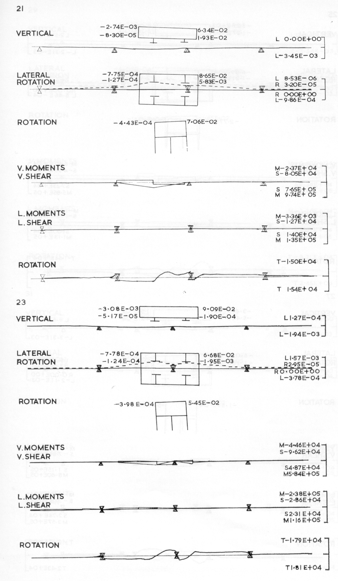
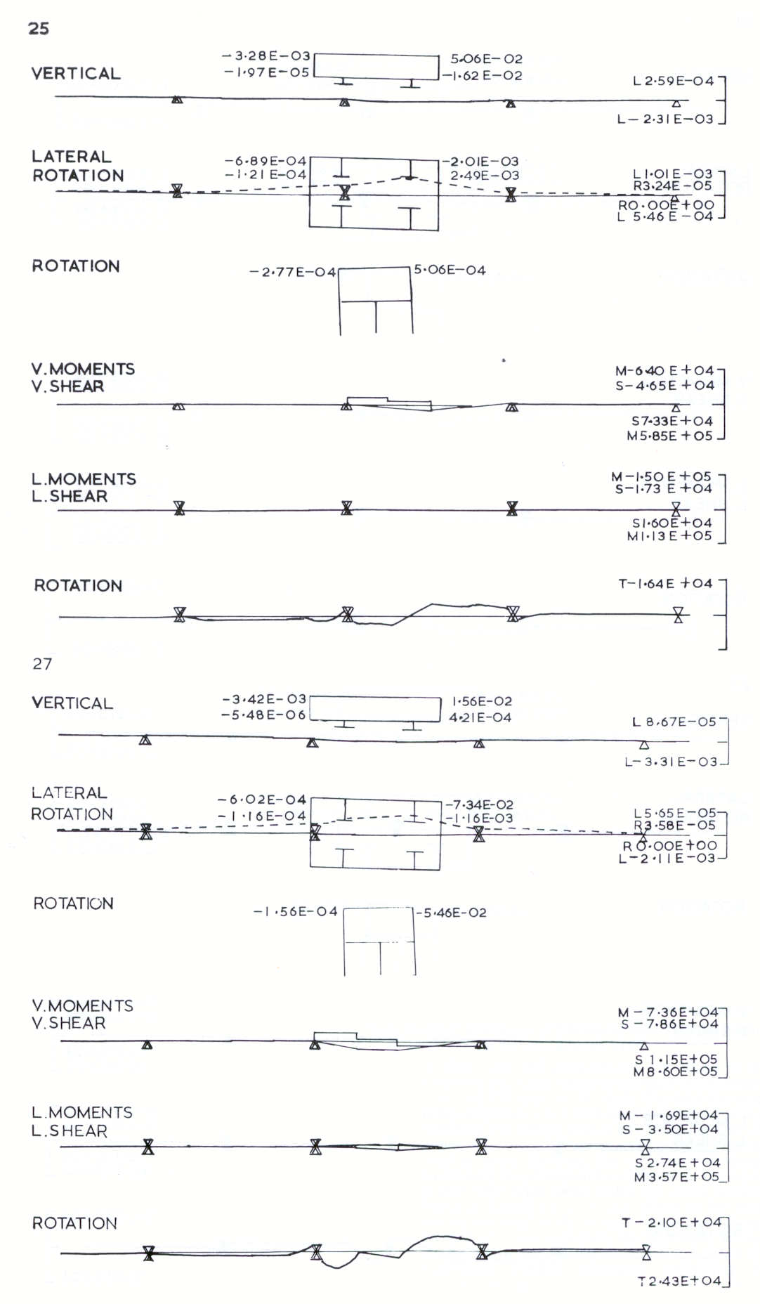
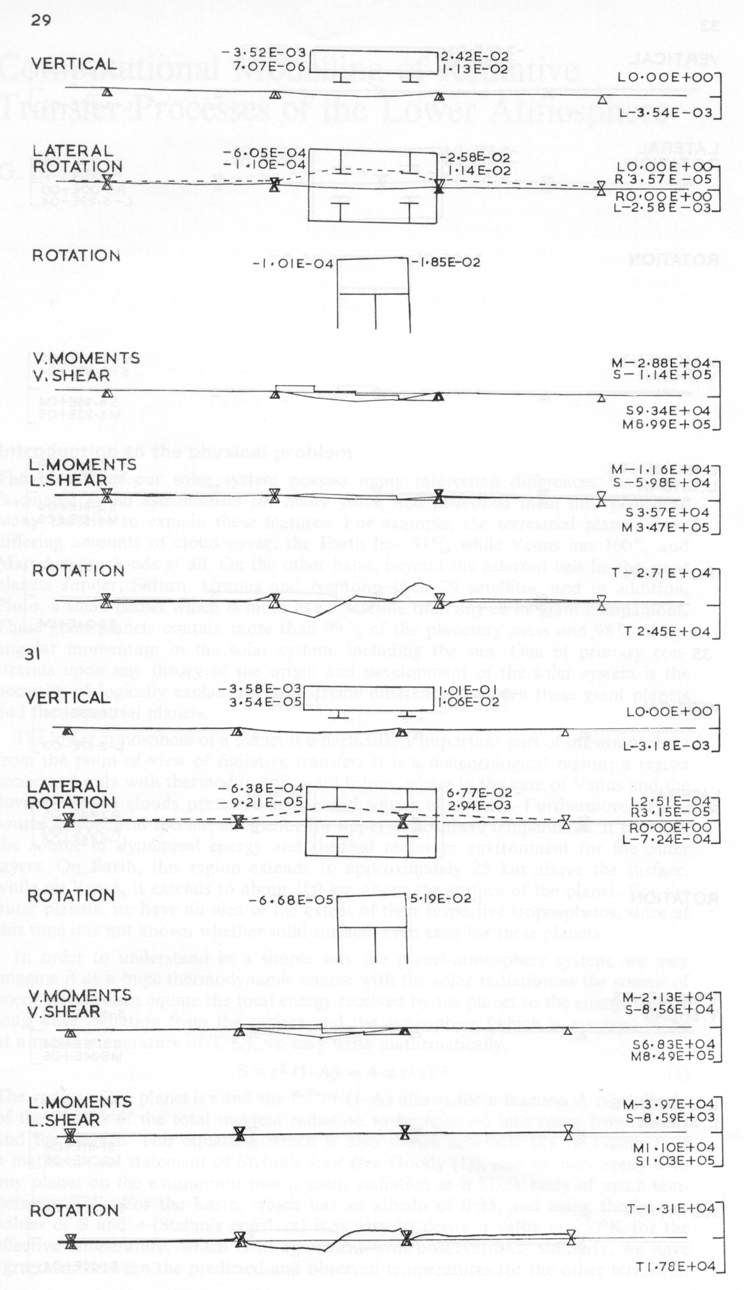
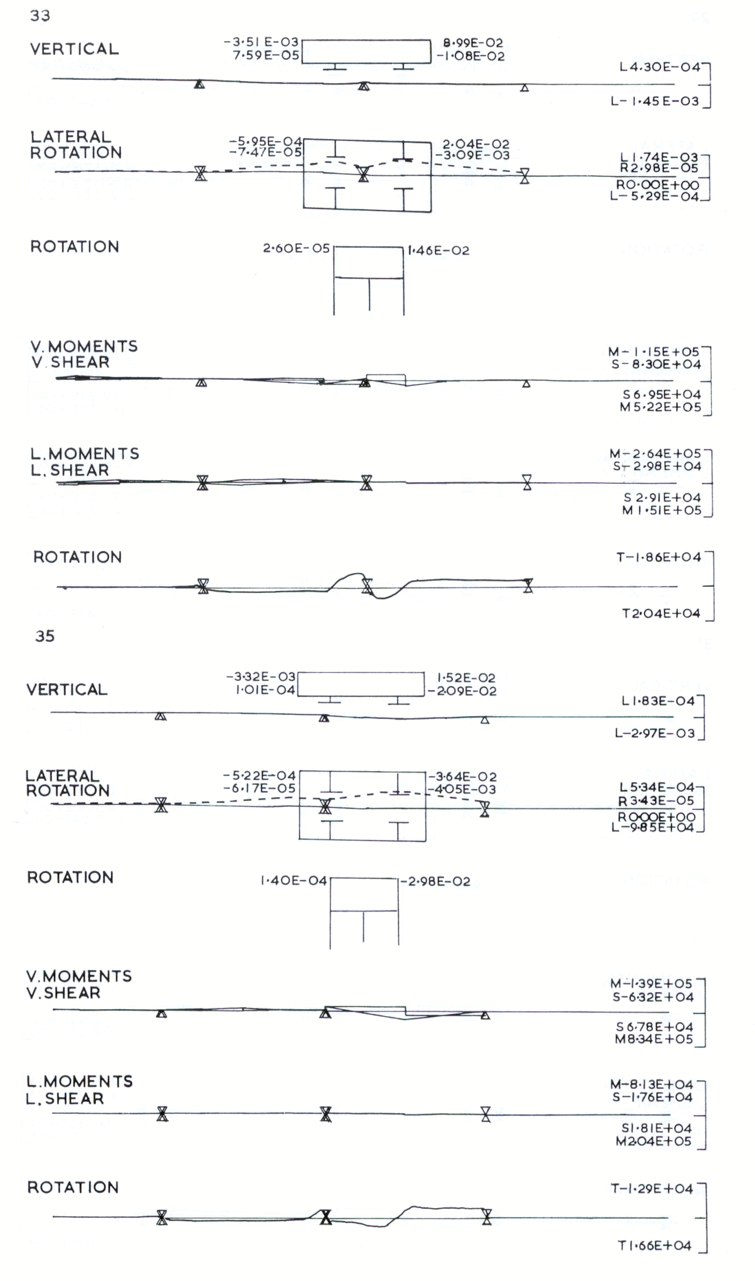
A side-view sequence showing a vehicle passing at 300 mph over one 75ft span in a continuous beam. Beam deflections can be seen on spans in front of, under and behind the vehicle and vehicle suspension movements are visible. Vehicle motion is small and has to be deduced from the figures written beside it. The bottom half of the picture traces bending moments and shear forces in the beam.
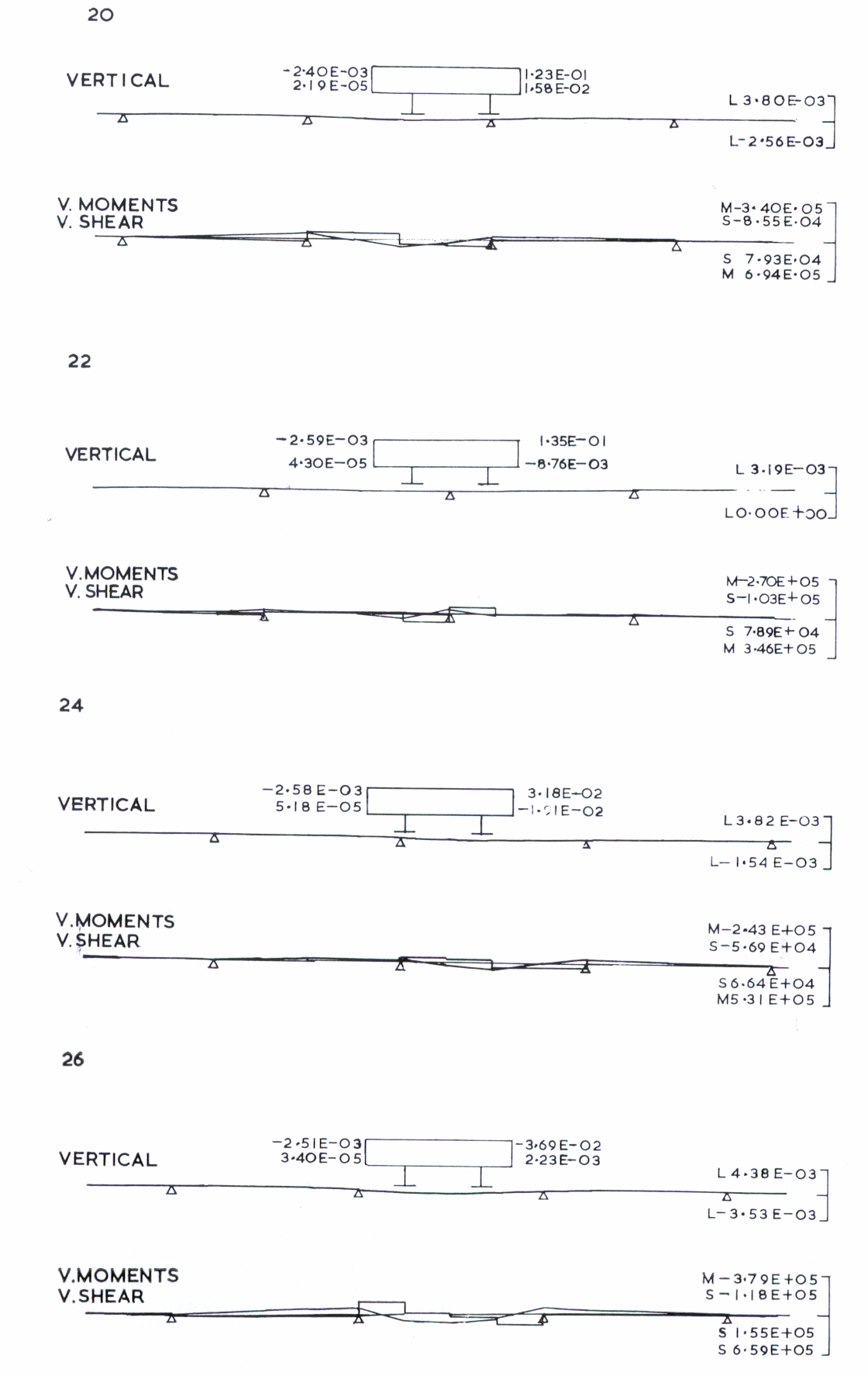
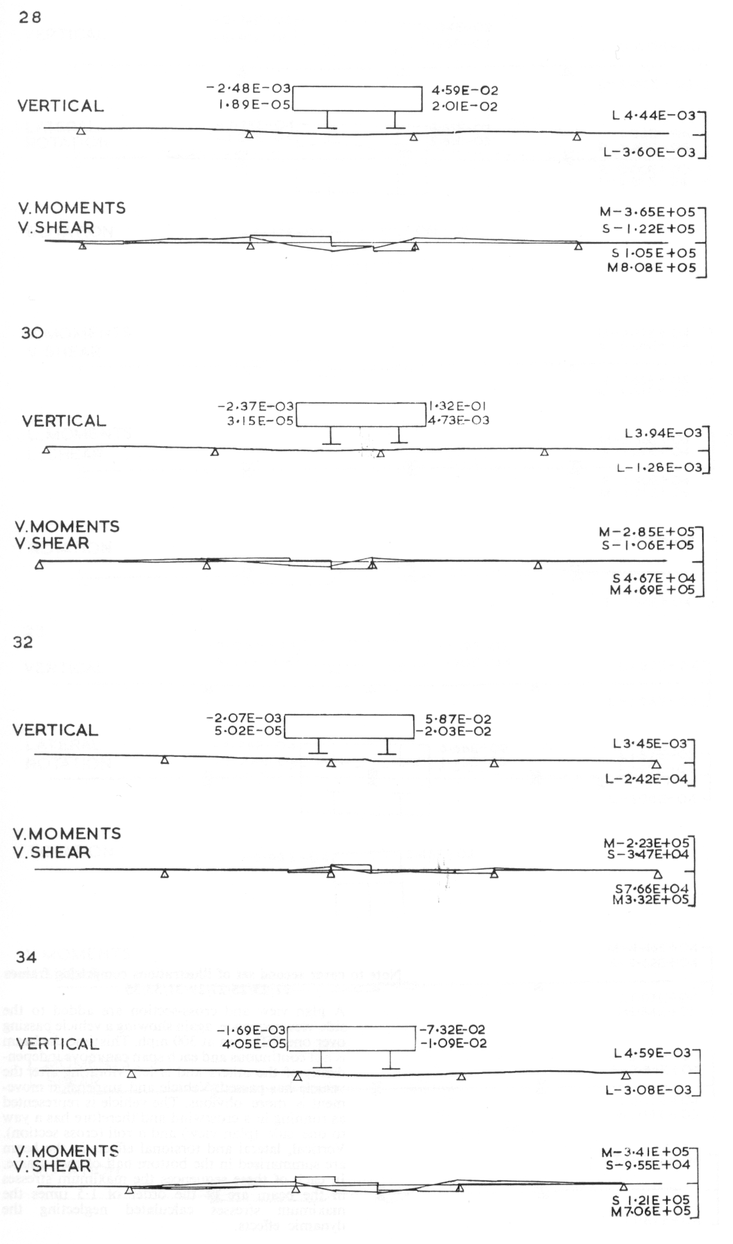
A plan view and cross-section are added to the side-view sequence, again showing a vehicle passing over one 75ft span at 300 mph. This time the beam is not continuous and each span can move independently of the others and is left vibrating after the vehicle has passed. Vehicle and suspension movement is more obvious. The vehicle is represented as running in a crosswind and therefore has a yaw to one side (plan view) and a roll (cross section). Vertical, lateral and torsional effects in the beam are summarised in the bottom half of each frame. In each of these sequences the maximum stresses in the beam are of the order of 1.5 times the maximum stresses calculated neglecting the dynamic effects.