
H. S. Harung, Royal Norwegian Navy; E. Lightfoot and D. M. Duggan, Department of Engineering Science, University of Oxford
Several single-storey model scaffold towers were loaded to collapse to indicate the effects of different bracing arrangements and couplers. They were also analysed for overall elastic instability by means of a modified finite displacements program, which added deflexions to co-ordinates as the loading was increased. No allowances were made for elastic connections or for eccentricity of bracing. The finite displacements method was also used to analyse two three-storey Millshore towers which had previously been tested. Several conclusions are drawn about the effects of different bracings and couplers. The overall elastic instability predictions were found to be within 20 per cent for the model tubular scaffolds and close enough for design, i.e. within about 10 per cent, for the full-scale towers. Failure by lateral-torsional buckling of the second Millshore tower which incorporated open section puncheons was correctly predicted. A design recommendation is made for the effective lengths of scaffold columns.
Several research projects have already been conducted into scaffolding [1,2,3], but none has yet (to the authors' knowledge) utilized the computer to predict overall elastic instability. A study of the safe usage of loadbearing scaffolding was initiated at Oxford University late in 1971; it was supported by the Science Research Council and linked with a field survey sponsored by the Construction Industries Research and Information Association in 1972. The collapse of various scaffolding and falsework systems during the pouring of concrete bridge decks in recent years has added some current interest to research in this area.
The possibility of predicting the collapse of model scaffold towers by overall elastic instability calculations was indicated in certain preliminary tests [4]; the extension of the analysis to allow for linear elastic connections has recently been achieved and could now be incorporated in the FDP (finite displacements program). The FDP was developed at the University of Manchester Institute of Science and Technology; the expertise there was made available to the scaffolding research team at Oxford. Details of this method in several of its applications may be found in references 5 to 9.
These were constructed from cold-drawn HT30 aluminium alloy tubes. The properties obtained experimentally are given in Table 1, where d is the inner diameter, D the outer diameter, A the cross-sectional area, I the second moment of area, J the second polar moment of area, E Young's modulus, and G the shear modulus.
| d mm |
D mm |
A mm2 |
I mm4 |
J mm4 |
E kN/mm2 |
G kN/mm2 |
|---|---|---|---|---|---|---|
| 3.6 | 6.5 | 29.3 | 79.5 | 159 | 69.0 | 26.2 |
TABLE 1-Properties of tubes used for model scaffolds
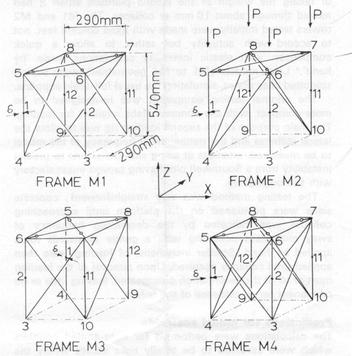
The overall dimensions of the four model scaffold towers tested, M1 to M4, are shown in Fig 1 where X, Y, Z are the frame co-ordinate axes. The height, t, of 540 mm between joints gives a slenderness ratio of 326 and an Euler load Pe ( = π2EI/l2) of 0.188 kN (for the pin-ended condition). The squash load Py ( = Aσy) is 9.10 kN (assuming a proof yield stress, σy, of 0.309 kN/mm2).
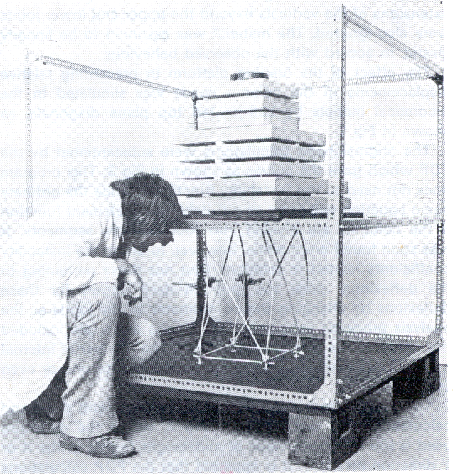
The testing arrangement is shown in Fig 2. The loading platform simulated stiff formwork and ensured that the column heads were fixed in their relative positions but were free to rotate in vertical planes. The top plane of any actual scaffold tower, however, mayor may not be fully restrained against such in-plane distortions. The platform also enabled the concrete slabs used for loading to be positioned symmetrically. These slabs were handled by means of a Sherpa loader and had wooden locating strips glued to their top and bottom sides. The Dexion framing provided a means of taking the weight of the loaded platform when it had moved through about 10 mm in collapse. The M1 and M2 towers tested initially were made with fixed column feet, not to accord with actuality but rather to allow a quick comparison with elastic instability calculations made by hand.[4] Later models (M1 to M4 geometries) were set on spigotted base plates, simulating the usual full-scale supports.
The original testing equipment was re-designed to be more compact, with the concrete slabs retained for loading. The main purpose of the second loading rig was to allow the lateral stiffness and the natural sway frequency of the model to be measured, attempts at using side deflexions to predict instability from a Southwell plot having proved unsatisfactory with the original rig.
The testing method was very straightforward; concrete slabs were positioned on the platform until approaching collapse was indicated by the decreasing frequency of sway movement occurring with a gentle sidewards force applied by hand. Smaller increments of loading were then applied until collapse occurred. Upon removal of the loading most or all of the deformation disappeared, leaving little or no permanent set as evidence of the failure.
The calculations were performed for right-angled couplers which were assumed to be totally rigid except where the couplers are specifically referred to as pinned. The joints were idealized to point positions and out-of-plane eccentricities of the horizontal and diagonal members were ignored. The extensions of the verticals beyond the upper and lower joints were also ignored. The material was assumed to be linearly elastic, in accord with the observed behaviour.
The effect of the loading platform in preventing relative displacements of the column heads was simulated in the theoretical models by ball-jointed top plane diagonals, as shown in Fig 1.
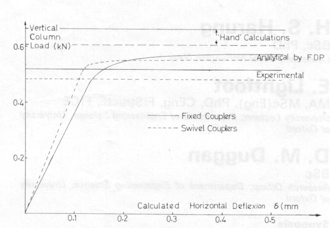
The original hand calculations were substantiated by the FDP which gave the curves as shown in Fig 3. This program does not need to use instability functions [10] since the ordinary beam equation will serve as a suitable finite element function if the columns are divided into four or more segments. It was soon found worthwhile, however, to utilize the instability coefficients related to rotations (but not those pertaining to the deflexions, since the program itself allows for these deflexions by changing the co-ordinates of the joints as the analysis proceeds incrementally). Thus sand c are included but not m, in the Merchant notation [10]. The number of internal nodes in each column could thus be reduced to one or even zero.
The results from the FDP are compared with the hand calculations and test results in Fig 3, where the deflexion used is the maximum value at mid-height (either in the X or Y direction on plan). It is apparent that the FDP calculations over-estimate the strength of M1 (with fixed column feet) by about 15 per cent, both for the diagonals secured by right-angled couplers and by swivel couplers. The towers with right-angled coupled diagonals were found experimentally to have about 7 per cent more strength than those with swivel couplers.
The FDP provides deflexions and rotations, with loading, at every node of the structure. Some of these displacements are better than others for indicating a particular overall mode of collapse; for comparison of one model with another, however, the deflexions chosen here were those at the mid-points of the columns.
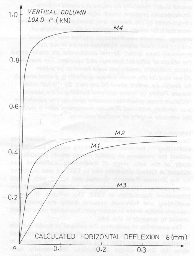
The FDP was utilized to investigate the effects of the different bracing arrangements shown in Fig 1, for the more realistic case of column feet located by spigots. This type of support may be assumed to allow rotations in any two vertical planes, but to be rigidly fixed against displacements and (because of friction) against twisting. The horizontal members near the base provide additional restraints which are allowed for in the calculations. The diagonals are secured by means of right-angled couplers.
Results are given in Fig 4. The diagonal bracings in M1 to M3 are clearly secondary, but are load bearing in M4.
In M1 it was found that the diagonals carried small compressive forces during the initial loading stages; later these became tensile as the diagonals attempted to restrain the top plane against its excessive rotation associated with collapse. The bracing in M2 provides a much greater stiffness against platform rotation but the eventual strength is only slightly greater than that of M1.
The bracing arrangement in M3 is perhaps unrealistic; it offers little resistance against twisting of the top plane and failure occurs with overall torsional buckling. The additional diagonals in M4, however, provide restraint to the heads of all the columns and all the diagonals prove to be loadbearing. Although this is an unusual bracing arrangement it might be worth adopting when additional strength is required of an existing scaffold.
It is sometimes considered good practice to use base ledgers on scaffolding; their effect on M1 to M4 is given in Table 2, where several results from the FDP and some experimental values are compared.
Only M2 was affected by the removal of the top bracing diagonals inserted to represent platform rigidity. With this bracing removed failure occurred with the two pairs of diagonals pushing their respective columns outwards, thus causing the other two columns to move inwards. The calculated collapse load was reduced to 0.33 kN for the pinned base case-a reduction to 78 per cent of the strength with a rigid platform.
The possibility of collapse due to uneven loadings on scaffold standards (columns) needs consideration since such loading cases can occur in practice (with, for example, heaped concrete during pouring or the stacking of bricks on access scaffolds).
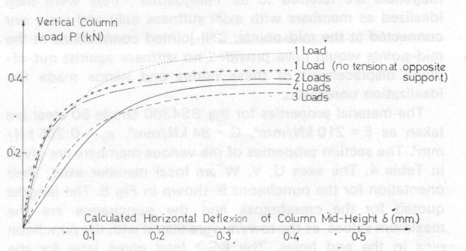
With only a single column load it was found that the opposite column tended to lift in towers M1 and M4. This tendency would normally be offset by the weight of the scaffolding itself or by additional vertical loads on all four standards. The column load versus mid-column deflexion plot for M1 given by the FDP is shown in Fig 5. Comparisons for all the towers are given in Table 3. Pinned feet without base ledgers are assumed throughout.
Examination of Table 3 reveals an important aspect of unsymmetrical vertical loading. It is seen that odd possibilities for collapse could occur in M1, M2 and M4 with the removal of a single column load from the fully loaded condition, for example, in M1 loads of 0.39 kN could be sustained by four columns but not by three. The usual factor of safety should, of course, remove this contingency entirely, but the reduction of the safety factor could possibly be significant when combined with other effects.
| Tower | Predicted collapse loads (kN) | Experimental collapse load (kN) |
Experimental support condition |
||
|---|---|---|---|---|---|
| (a) Pinned |
(b) Pinned with base beams |
(c) Rigid |
|||
| M1 | 0.390 | 0.461 | 0.583 | 0.515 | |
| M2 | 0.430 | 0.493 | 0.578 | 0.542 | |
| M3 | 0.143 | 0.246 | 0.336 | 0.287 | |
| M4 | 0.695 | 0.938 | 1.05 | 0.780 | |
TABLE 2 - Effect of base rigidity on scaffold tower strength (values in kN on each column)
| Loads at | |||||||||
|---|---|---|---|---|---|---|---|---|---|
| Tower | (a) One Column |
(b)* One Column |
(c) Two Columns |
(d) Three Columns |
(e) Four Columns |
||||
| Node | kN | Node | kN | Node | kN | Node | kN | kN | |
| M1 | 5 | 0.475 | 5 | 0.426 | 5,8 | 0.404 | 6,7,8 | 0.372 | 0.390 |
| M2 | 8 | 0.460 | 5,8 | 0.440 | 6,7,8 | 0.420 | 0.430 | ||
| M3 | 5 | 0.204 | 5,8 | 0.168 | 5,6,7 | 0.175 | 0.143 | ||
| M4 | 5 | 0.805 | 5 | 0.650 | 5,8 | 0.670 | 6,7,8 | 0.620 | 0.695 |
TABLE 3 - Column loads for collapse of scaffold towers (see Figs 1 and 5)
* In case (b) above, the opposite column to that loaded is permitted to lift.
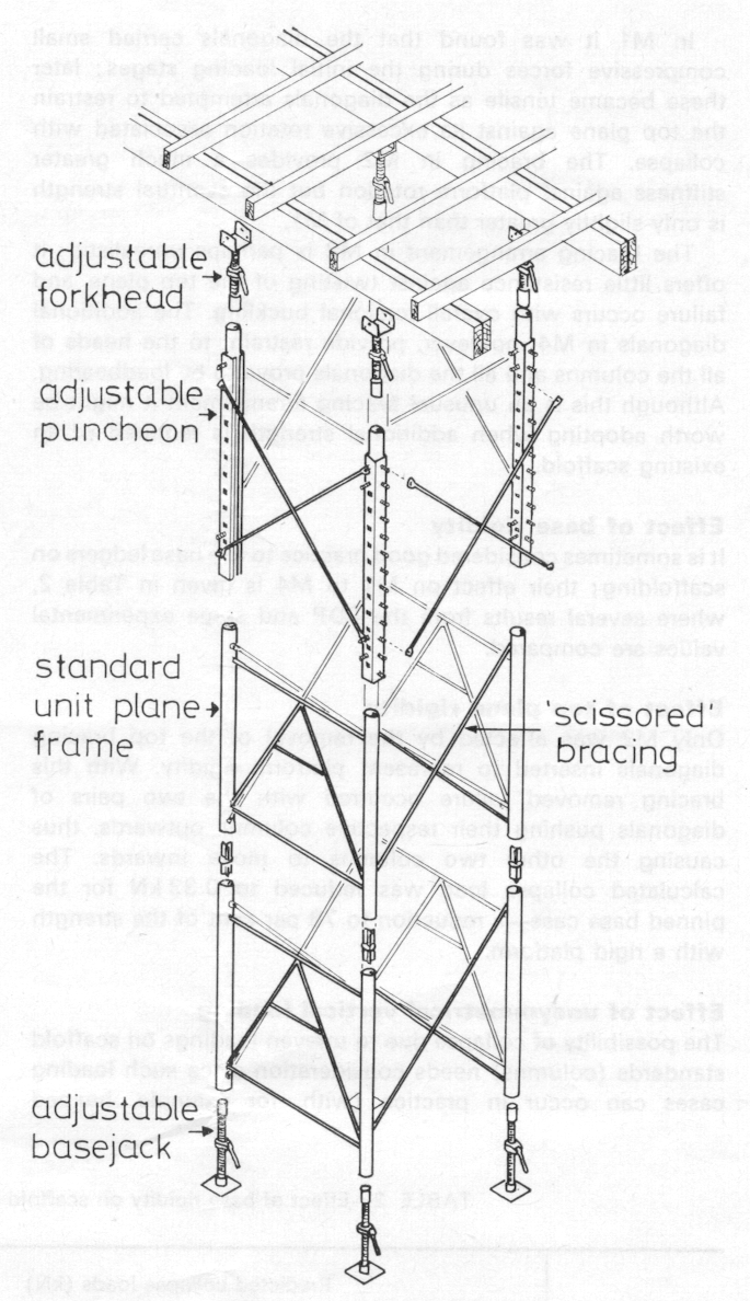
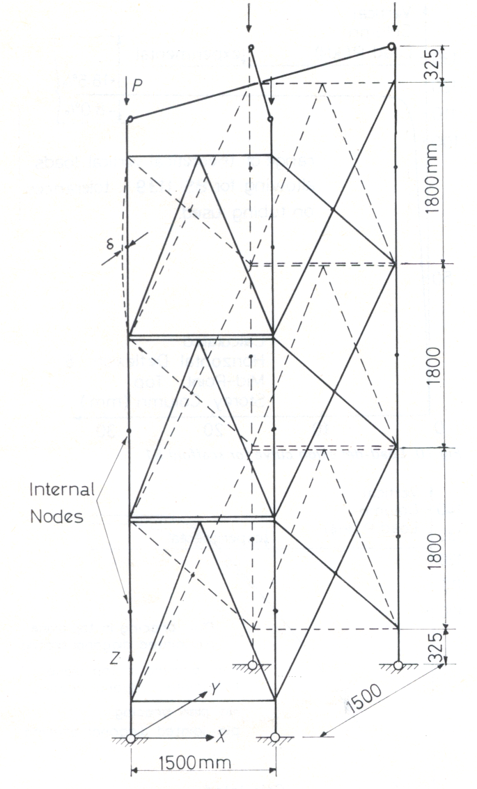
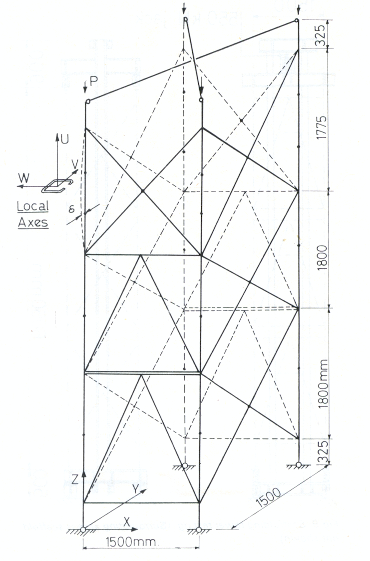
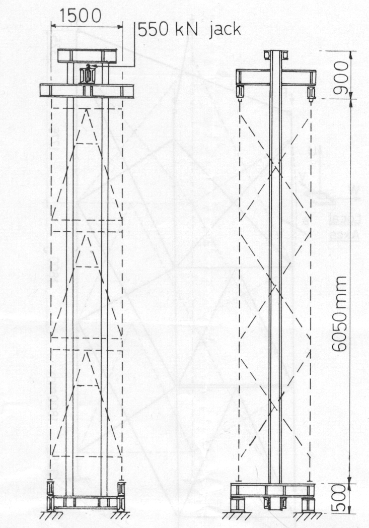
Two three-storey Millshore towers were tested to failure [11] in 1968. The first of these, S1, was assembled from three standard lifts, the second, S2, from two standard lifts plus a top adjustable lift consisting of open sections (puncheons) set at their maximum extended position - see Fig 6. The idealizations of S1 and S2 are shown in Figs 7 and 8; it will be seen that the bracings have been slightly modified to reduce the number of nodes. Also, for the analysis, the spigotted joints between the lifts have been assumed to be rigid. The extension of the forkheads and base jacks is adjustable between 100 mm and 355 mm. The bracing diagonals are mounted on pegs at their ends and joined by pins at their midpoints. There is therefore zero resistance against in-plane bending at these joints but some restraint against out-of-plane bending and torsion. If these restraints occur the diagonals are referred to as pinned; they were then idealized as pin-ended members with a common node at the mid-points and the continuity of each brace over the common middle node was ignored. If the restraints are considered not to occur the diagonals are referred to as ball-jointed; they were then idealized as members with axial stiffness only and were not connected at the mid-points. Ball-jointed connections at the mid-points would have provided no stiffness against out-of-plane displacement of these nodes and hence made the idealization unrealistic.
The material properties for the B84360 Grade 50 steel are taken as E = 210 kN/mm2, G = 84 kN/mm2, σy = 0.355 kN/ mm2. The section properties of the various members are given in Table 4. The axes U, V, W are local member axes; their orientation for the puncheons is shown in Fig 8. The lengths quoted for the crossbraces and the puncheons are the maximum values, as the towers were tested with the puncheon pins in the end holes. The Euler load given later for the puncheon is based on the largest second moment of area Iw, since the towers fail in the YZ rather than in the XZ planes because of the bracing arrangements. The Wagner torsional buckling load is PT= GJA/(IV+ IW) and the reduced torsional stiffness of the puncheon is kT = (GJ - P(IV+ IW)/A)/L. In the tubular columns the Euler buckling load is much less than the torsional buckling load, so only one internal node has been taken to detect buckling via lateral displacements. For the puncheons, however, two internal nodes have been taken (though in fact one would have been sufficient to reveal the non-linear variation of twist with loading associated with lateral-torsional buckling).
| A (mm2) |
IV
(mm4) |
IW
(mm4) |
J (mm4) |
Member projections (mm) |
|||
|---|---|---|---|---|---|---|---|
| X | Y | Z | |||||
| Vertical tubes | 715 | 286 × 103 | 286 × 103 | 572 × 103 | - | - | 1800 |
| Horizontals | 261 | 32.4 × 10³ | 32.4 × 10³ | 64.8 × 10³ | 1500 | - | - |
| A-frame bracing | 261 | 32.4 × 10³ | 32.4 × 10³ | 64.8 × 10³ | 750 | - | 1800 |
| Diagonal bracing | 261 | 32.4 × 10³ | 32.4 × 10³ | 64.8 × 10³ | - | 750 | 900 |
| Forkheads and basejacks | 840 | 56 × 103 | 56 × 103 | 112 × 103 | - | - | 350 |
| Puncheons | 795 | 403 × 103* | 495 × 103* | 5.75 × 10³* | - | - | 1775 |
* Properties determined experimentally
TABLE 4-Section properties for full-scale scaffolds
The FDP used here is based on a centroidal idealization of the members and neglects any increase in torsional stiffness due to warping restraint. For the puncheon cross-section the shear centre is off-set from the centroid along the W-axis (see Fig 8) and warping restraint is provided by a short length of tube welded to the top. Also, the puncheons contain a number of square holes to allow for height adjustments. Because of these complications the puncheon properties were obtained experimentally. A test rig was set up to investigate the behaviour of the puncheon under bending about both axes and torsion. The bending and torsion properties given in Table 4 were thus obtained. The values derived from nominal dimensions are IV = 427, IW = 545, and J = 4.8, all in mm4 × 103. As may be expected, the difference is greatest for the torsional constant.
With the base jacks and forkheads fully extended and with the Mills jacking system and test rig shown in Fig 9, tower S1 was found to fail at 128 kN per column (average of three tests). In a similar manner tower S2 was found to fail at an average column load of 125 kN (this value was confirmed in a later test witnessed by two of the authors when the total failure load was just short of 510 kN). Though no special provision is made for lateral freedom for the jack and reaction platform, the test rig has little lateral strength and is not thought to provide much, if any, restraint against any possible side sway of the tower. The analysis showed, in fact, that the basic modes of collapse of these towers did not involve overall side sway.
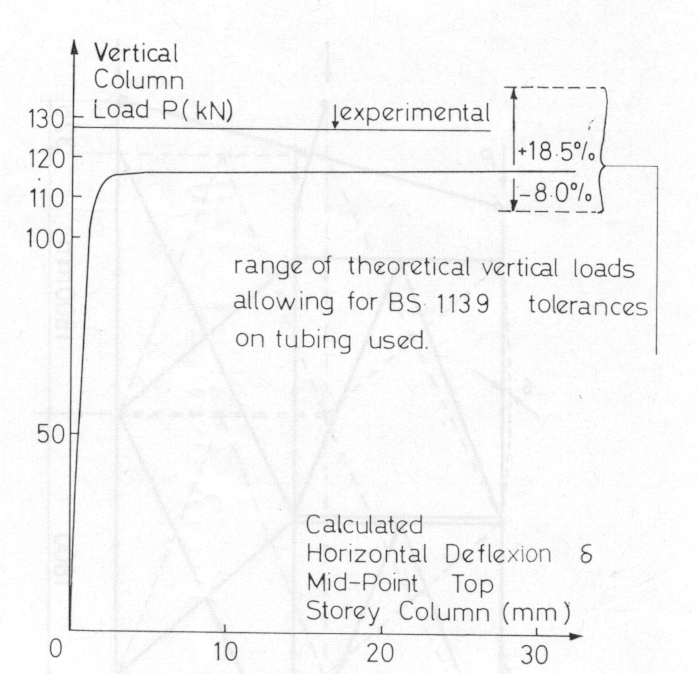
Fig 10 shows a calculated column load-lateral deflexion curve for S1. The predicted failure load is around 9 per cent low at 116 kN per column. This may be accounted for by the actual members having larger cross-sections than the assumed nominal values. By allowing for the full range of tolerances on the dimensions of the vertical tubing, the range of predicted failure loads as shown in Fig 10 is obtained. Further discussion of this point is given later.
The simplification of the geometry shown in Fig 7 would almost certainly result in idealized towers having less strength than the actual towers. On the other hand, the assumption of full continuity at the spigot joints connecting the vertical tubes would tend to make the idealized towers stronger. These various factors cannot be separately assessed now; it is merely noted that the predictions for these full-size towers are now more satisfactorily on the low and safe side, whereas those for the models were high and unsafe.
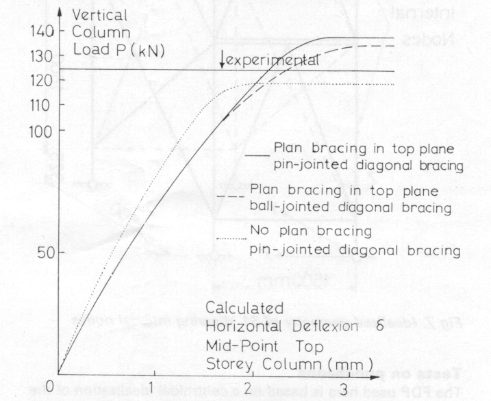
The stiffness of the loading platform of the test rig in Fig 9 is simulated by the plan bracing shown in Figs 7 and 8. The authors believe this approximation to be realistic. The bracing has the same effect as that already described for the model towers. For an actual scaffold tower under loading transmitted by formwork there is a possibility that the top plane stiffness could be fairly low. Removal of the plan bracing from the theoretical model causes a reduction in the calculated failure load of 16 per cent for S1 and 14 per cent for S2 (see Fig 11). This indicates that the strength of a scaffold tower depends to some extent on the stiffness of the formwork.
A comparison is made in Fig 11 of the load-deflexion curves of S2 for the cases of pin-jointed and ball-jointed cross-bracing mentioned earlier.
In the design of the Millshore towers the effective length of a column was taken as the full storey height. Thus in S1 the Euler load turned out to be 182.4 kN for each column in each storey, whereas the collapse load was found to be 128 kN on each column. An effective length factor of 1.20 could therefore be said to apply. This agrees well with a factor of 1.18 obtained by measuring the largest distance between adjacent points of contraflexure (zero bending moment) on the buckled columns in the analysis. Plastic yield was of negligible importance prior to buckling as is suggested by the relatively high value of 253.8 kN for the tube column squash load.
For the puncheons in S2 the Euler load, on the full storey height, works out to be 264.6 kN. The Wagner torsional buckling load calculates at 427.5 kN and the squash load at 282.2 kN. Since S2 sustains almost the same collapse loading (125 kN for the three earlier tests) as S1 it might be thought that the tubing in the lower two storeys would be the cause of the collapse, but the torsional-flexural buckling in the top storey is an established fact.
The relatively low value of the puncheon squash load in relation to its theoretical elastic failure load, suggests that plasticity will be of greater importance for S2 than for S1. This view was supported by examination of the member forces given by the analysis as failure was approached. The magnitude of the forces indicated t hat the stresses in the puncheon were greater than the assumed yield stress. In addition, the authors observed a permanent set in the puncheon after the failure of S2. The FDP as used here makes no allowance for yield; this probably accounts to a large extent for the difference in the theoretical failure loads for the two towers being much larger than the difference in the actual failure loads.
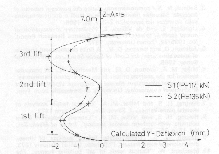
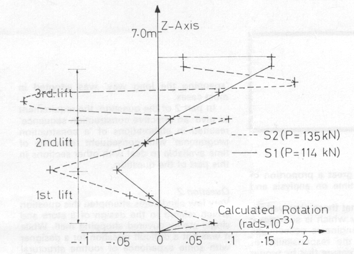
The lateral deflexions over the entire height, indicating the collapse modes for S1 and S2, are shown in Fig 12. The curves are those for the frames with plan bracing and pinjointed cross-bracing. The cross-bracing seems to be remarkably effective in preventing overall sway of the towers. It would appear that the higher bending stiffnesses of the puncheons above those of the usual tubes causes the maximum lateral deflexion to occur in the first lift of S2 in contrast to the third lift of S1. Fig 13 is included to show the way S2 collapses in torsional-flexural buckling. The twisting of the column in the top storey exceeds that of S1 and increases in the usual asymptotic manner with loading. The tower tested to failure in the presence of the authors exhibited this twisting-bending mode of collapse; it is gratifying to find such a complex mode of failure predicted correctly by the FDP.
In the full-scale tests on the Millshore towers the actual thicknesses of the various components were not measured; units selected at random were used to build representative structures. For the sort of analysis performed in this paper some idea of the properties of the tube cross-sections would have proved useful. The puncheons actually tested for bending and twisting stiffnesses were selected at random from stock in 1973 and might well be appreciably different from those used in the towers.
Scaffolding in the UK is designed to BS449, The use of structural steel in building, with further guidance from Addendum No.1, P04064 The use of cold formed steel sections in building when sections similar to the puncheons are used. The mild steel used in ordinary tube and fittings scaffolding is to grade 13 of BS1775, but the Millshore system uses high tensile steel to BS968. BS968 has been superseded by BS4360, Grade 50. There are two BSI publications pertaining particularly to scaffolding, CP97 Metal scaffolding and BS1139 Specification for metal scaffolding. These are largely descriptive, but give some guidance on bracing arrangements and effective lengths. The report of the joint committee Falsework (1971) contains more useful information.
Conventional deterministic design methods usually employ nominal dimensions, though allowable production margins can result in appreciable differences. Thus, for the No. 8 gauge thickness tubing in the Millshore towers, BS1139 allows an OD tolerance of + 0.9 per cent, - 0.7 per cent, a thickness tolerance of +20 per cent, -10 per cent, and a weight specification of not less than 7% per cent under the nominal weight. These tolerances result in a possible variation of the second moment of area of the tube section of +18.5 per cent, -8 per cent, the effects of which are shown in Fig 10. It is unlikely that an increase in strength of as much as 18.5 per cent would be found in a particular tube, but the fact that the upper tolerance is so much greater than the lower tolerance ensures that in the majority of cases, the properties of the tubes are in excess of the nominal values. The incidence of under-strength tubes is quite low and although the designer should be aware that specifications allow a shortfall of 8 per cent in the second moment of area, it is unlikely that this is a significant factor in the collapse of scaffold structures in general.
This particular investigation is relevant to the conventional design method in providing values of the elastic buckling loads of scaffold towers. It has already been remarked that an effective length of 1.2 times each lift height would be more appropriate, and safer, too, for design.
Once side loading due to windage and other effects is taken into account the structural behaviour will no longer approach the incipient buckling situation occurring with vertical load alone (as considered here). The conventional design method attempts to produce sections which will start to yield only when some factored increase of the design loading is applied. The FDP will extend [7-9] to follow the actual behaviour of a structure as plasticity occurs and could be applied with side loading etc. as a complete design check; it has not yet been so utilized for scaffolding but it could become a very powerful design aid.
It has been shown, both in model and full-scale scaffold towers, that failure to sustain vertical loading is largely accounted for by overall elastic instability. The usual trial and error method for finding at what load factor the stiffness matrix for an entire structure is equal to zero can be used, but a better idea of the structural behaviour up to collapse is obtained from the finite displacements program, which allows displacements to be obtained with increasing loading, allowance being made for the deformed geometry of the structure. With the elastic load factor known, appropriate effective lengths can be obtained for the column members for use in design.
The tests have indicated that the assumption of full fixity at couplings is not far from actuality in models; if this is later found to hold for full-scale tube and fittings scaffolds then the calculation methods already applied can be used for investigating diverse scaffolding structures.
In the Millshore towers the assumption of full fixity at spigots in standards has been shown to be allowable (an interesting point, because some other scaffolding systems have been found to articulate at such joints). Also the complication of open sections, even in producing twist-bend buckling, has been easily handled by the finite displacement program with only two intermediate nodes per column.
This research has shown that scaffold towers could be 8 per cent under strength because of production tolerances in tubes; also that the effective lengths of columns should be taken as 1.2 (or some other appropriate factor) times the height of each storey.
The possibility of using the FDP as a complete design method to improve simpler conventional design procedures has now become apparent and may be applied to scaffolding in further research.
The authors would like to thank the Science Research Council, not only for financial support but also for the faith and encouragement of those of its officers involved.
The secondment of Dr. H. S. Harung to Oxford University and the use of the UMIST finite displacement program was very kindly arranged by Mr. M. A. Millar, Dr. D. M. Brotton and Professor S. S. Gill. Computing facilities were provided by the Atlas Computing Laboratory at Chilton and by the Oxford University Computing Laboratory.
Unreserved co-operation was provided by Mr F. Carr of GKN, London and by Mr C. Wheelock of Mills Scaffolding Co. Ltd., Research and Development, Bristol, who supplied calculations and specimens and arranged a special test demonstration.
1. Sanpaolesi, L. and Gucci, N. 'Esperienza du ponteggi a telaio' Pubblicazione No 92, Instituto di Scienza della Costruzioni, Universita di Pisa, 1962.
2. Sanpaolesi, L. and Salinari, N. 'Sul carico critico di ponteggi tubolari di grande altezza', Pubblicazione No 112, Instituto di Scienza della Costruzioni, Universita di Pisa, 1965.
3. Salinari, N. 'Sul comportamento statico dei ponteggi tubolari di bacciata'. Securitas (revista mensile di studi e documentazione sulla sicurezza nel lavoro), n 2-3, v. 53, 1968.
4. Lightfoot, E. and de Villiers, E. 'Preliminary investigation of model scaffold towers'. Engineering Science Research Report, No.1035/72, Oxford University, 1972.
5. Johnson, D. and Brotton, D. M. 'A finite dlsplacement analysis of space structures', Int. Conf. of Space Structures. University of Surrey, 1966.
6. Millar, M. A., Brotton, D. M. and Merchant, W., 'A computer method for the analysis of non-linear elastic plane frameworks', International symposium, the use of electronic digital computers in structural engineering, University of Newcastle upon Tyne, 1966.
7. Harung, H. S. and Millar, M. A. 'General failure analysis of skeletal plane frames', J. Struct. Div.. ASCE, June 1973.
8. Harung, H. S. and Millar, M. A. 'Laterally restrained beam columns with uniform biaxial loading', Int. J. of Mech. Sci.. Vol. 15, p. 765-773.
9. Harung, H. S. 'Elastic-plastic failure analysis of three-dimensional skeletal frames', PhD thesis, UMIST, January 1973.
10. Merchant, W. 'Critical loads of tall building frames', The Structural Engineer, March 1955.
11. Internal report of Mills Scaffolding Co., Job No. 96.
