
2.1 A standard FR 80 includes either a 7-track (556/800 bits per inch - bpi) or 9-track (800 bpi) magnetic tape transport. These tape drives may be used in any combination up to a total of four, and operate at a speed of 37-1/2 inches per second (ips), providing a maximum transfer rate of 30,000 characters per second (cps) for an 800 bpi drive. Optional tape drives include a 75 ips version of the above two drives, with a maximum data transfer rate of 60,000 cps for an 800 bpi drive.
2.2 A 1600 bpi tape drive is also available for the FR 80. Its speed is 37-1/2 ips, with a maximum data transfer rate of 60,000 cps. It is available as 1600 bpi read/ write or dual read 1600 bpi phase encoded/800 NRZI.
2.3 The forenamed magnetic tape drives are IBM tape-compatible. A write feature is standard and is required for each FR 80.
2.4 The FR 80 utilizes an ASR-33 Teletype for communication with the controller. An optional ASR-35 Teletype is available. The Teletype includes a 10 cps paper tape reader and paper tape punch. High-speed paper tape readers and punches are optionally available. The paper tape reader is used for the bootstrap loader and various other utility routines. When compiling forms on an 8K tape system, both the reader and punch are required.
2.5 The standard FR 80 contains a 10" x 13" cathode-ray tube display monitor. The monitor is driven by the same deflection system as the recording precision CRT. Therefore, it displays exactly what is being recorded on film. In addition, there is a view-only capability which allows the display to be on the monitor and not on the recording CRT.
2.6 While the system is in the idle status, the current settings of the resident simulator are continuously refreshed on the monitor, which also serves as a display for use in designing forms. The monitor is also very helpful for editing and debugging software, as well as for analyzing magnetic tape records.
2.7 The FR 80 can generate either cine or comic mode microfilm in all available cameras. The technique of accomplishing this is unique in that it is done completely through a software mode set in the FR 80. The advantage of this capability is that the CRT is not manually rotated, thus eliminating potential CRT alignment and camera focus problems.
2.8 There is provision in the FR 80 for an optional disk drive and controller. The disk is a fixed-head type (non-removable) with a capacity of 262,144 18-bit words and an average access time of 16 milliseconds. The transfer rate is 3 megabits per second. Uses of the disk include:
2.9 A forms overlay capability is standard on the FR 80. Forms are created on the FR 80 through the use of a special software package. A form can be designed and verified by an FR 80 operator with a minimum amount of experience. Forms generation is an integral part of the operator training course. A properly trained operator will require approximately one hour to design a typical computer printout form containing both vectors and characters.
2.10 The FR 80 utilizes a 5" precision CRT for the recording of print and plot data. The CRT is optically flat and has a programmable raster of 16,384 by 16,384 points, for a total of more than a quarter of a billion addressable locations. As part of the deflection circuitry, there is sophisticated correction logic to compensate for geometric distortion common to CRT display systems.
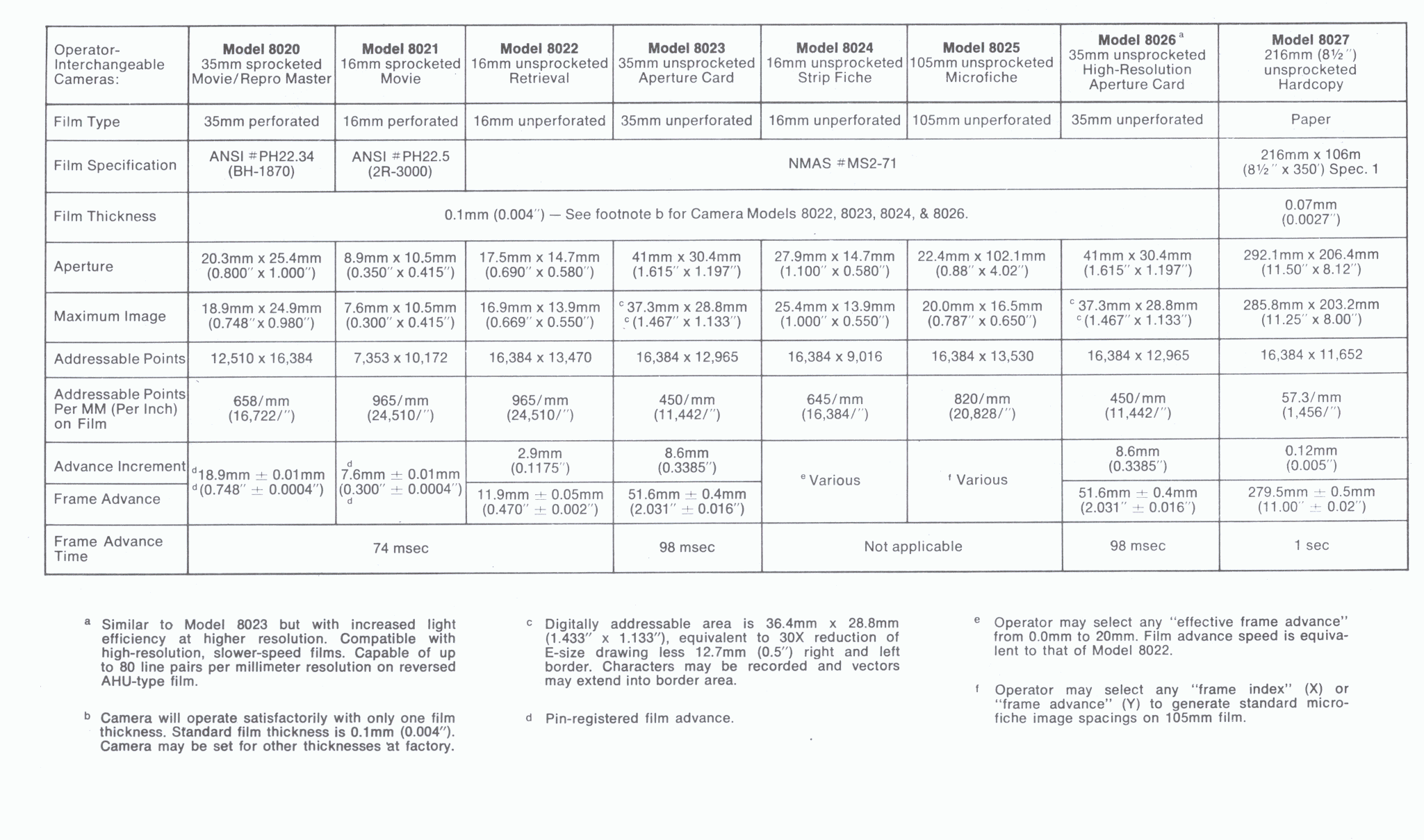
2.11 The image size is continuously variable for all cameras and film sizes up to the maximum image size (see table 2-1 for FR 80 film formats). Image size scaling is done automatically through the use of standard FR 80 software and requires no special training or lens movement on the part of the operator. Exact image size is selected by the operator, scaled by software (including character size selection), and recorded on film. Following are two examples showing the steps in determining the proper scaling.
2.12 To find the proper image size, use the following formula:
Image Size  ×  Number of scope  =  Image size in   (2-1)
in inches      points per inch     scope points
Example: A 3/4" grid is to be plotted with the 35mm unsprocketed camera.
0.75 × 11,442 = 8582
The image size will be set to 8582 scope points.
2.13 To find the proper spacing and line feed values for a given reduction, use the following formulas:
Number of scope   /  Given reduction ×  10  =  Standard character spacing  (2-2 )
points per inch                                      in scope points
Character spacing ×  5 / 3 = Standard line feed in scope points (2-3)
Standard refers to the normal 10 characters per inch and 6 line feeds per inch on a line printer.
Example: A print tape is to be recorded with the 16mm unsprocketed camera at a 15 times reduction.
24,510 / 150 = 163, and 815 / 3 = 272.
The character spacing and line feed values will be set to 163 and 272 scope points, respectively.
2.14 Frame butting accuracy is a function of camera pulldown accuracy. Unperforated cameras operate with roller pulldown, which can produce a slight variation from frame-to-frame. Normally, this is adequate for data recording purposes.
2.15 An optional, sprocketed, pin-registered camera provides accurate frame butting. The camera specification calls for a pulldown accuracy of ±0.0004". This is better than the tolerances for positioning the sprocket holes in the film!
2.16 The standard FR 80 draws vectors through the use of a vector generator rather than by point plotting. Under program control, vectors can be drawn between any two addressable points at anyone of eight line widths and eight levels of intensity.
2.18 Color recording is available on the FR 80 as an option. The option requires that a special color-recording CRT be substituted for the standard black-and-white CRT. (The color CRT can be used for normal black-and-white recording, but a slight loss in resolution will be evident.) The color CRT phosphor has a spectral light output that will expose all three layers of the color film.
2.18 Physically, the color unit has three color filters: red, green, and blue. Under program control, the proper filter is inserted into the optical path. A standard FR 80 subroutine controls filter movement. Each selective filter allows exposure of only the corresponding layer of the color film. The following paragraphs indicate the number of hits (repeats of the same data) required to produce different colors.
2.19
White  = 1 red hit, 1 green hit, 1 blue hit
Blue   = 1 blue
Green  = 1 green
Red    = 1 red
2.20
White      = 1 red hit, 1 green hit, 1 blue hit
Blue       = 1 blue
Blue/green = 1 blue, 1 green
Green      = 1 green
Yellow     = 1 green, 1 red
Red        = 1 red
Violet     = 1 red, 1 blue
2.21
White            = 2 red hits, 2 blue hits, 2 green hits
Blue             = 2 blue
Blue/blue-green  = 2 blue, 1 green
Blue/green       = 2 blue, 2 green
Blue/green-green = 1 blue, 2 green
Green            = 2 green
Yellow/green     = 2 green, 1 red
Yellow           = 2 green, 2 red
Orange           = 1 green, 2 red
Red              = 2 red
Violet           = 2 red, 2 blue
Red/violet       = 2 red, 1 blue
Blue/violet      = 1 red, 2 blue
2.22 The data tape need only specify the color required; standard FR 80 software keeps track of the filters and the number of hits. Throughput is increased by organizing the input data so that all of each color is recorded at the same time.
2.23 The FR 80 has extreme flexibility in hardware character generation. Rather than use a hard-wired character set, which limits recording to a single fixed font, the FR 80 stores the character set in core. Consecutive jobs can use different character sets and even different fonts without any alteration to the FR 80.
2.24 By using a very compact notation, the FR 80 standard 128-character set requires approximately 800 words of core. The core required for each FR 80 program includes space for the character set.
2.25 The standard character generator cycle steals the compacted character representation from core, interprets and records the character, and spaces in preparation for the next character. The high-speed character generator, part of the optional high-speed page composition system, incorporates the bookkeeping functions into the hardware. That is, a pointer to the beginning of a print line is handed to the character generator, and the entire print line is recorded before interrupting the program. The program can be doing other work while the print line is being recorded.
2.26 The FR 80 has three standard fonts: III, OCR-B, and NMA Microfont, and an optional directory font (see Chapter 7 for character codes). III has designed over 200 basic characters and symbols. A reasonable number of special characters can be incorporated into FR 80 programs for special applications, e.g., logic diagrams from line printer output.
2.27 The FR 80 character generator records 64 character sizes. Table 2-2 shows the character height for each size. Since the three standard fonts have an aspect ratio of 10 x× 14, the normal character spacing is equal to the character height. In fact, when size is not specified, the FR 80 software will automatically choose the proper character size based on the character spacing.
[The term "scope points" 16,384 scope points refers to the addressable raster i.e. there are 16,384 scope points across the full CRT image in each direction]
| Character size | Height in scope points |
Character size | Height in scope points |
|---|---|---|---|
| 0 | 12.6 | 32 | 147.0 |
| 1 | 16.8 | 33 | 151.2 |
| 2 | 21.0 | 34 | 155.4 |
| 3 | 25.2 | 35 | 159.6 |
| 4 | 29.4 | 36 | 163.8 |
| 5 | 33.6 | 37 | 168.0 |
| 6 | 37.8 | 38 | 172.2 |
| 7 | 42.0 | 39 | 176.4 |
| 8 | 46.2 | 40 | 180.6 |
| 9 | 50.4 | 41 | 184.8 |
| 10 | 54.6 | 42 | 189.0 |
| 11 | 58.8 | 43 | 193.2 |
| 12 | 63.0 | 44 | 197.4 |
| 13 | 67.2 | 45 | 201.6 |
| 14 | 71.4 | 46 | 205.8 |
| 15 | 75.6 | 47 | 210.0 |
| 16 | 79.8 | 48 | 214.2 |
| 17 | 84.0 | 49 | 218.4 |
| 18 | 88.2 | 50 | 222.6 |
| 19 | 92.4 | 51 | 226.8 |
| 20 | 96.6 | 52 | 231.0 |
| 21 | 100.8 | 53 | 235.2 |
| 22 | 105.0 | 54 | 239.4 |
| 23 | 109.2 | 55 | 243.6 |
| 24 | 113.4 | 56 | 247.8 |
| 25 | 117.6 | 57 | 252.0 |
| 26 | 121.8 | 58 | 256.2 |
| 27 | 126.0 | 59 | 260.4 |
| 28 | 130.2 | 60 | 264.6 |
| 29 | 134.4 | 61 | 268.8 |
| 30 | 138.6 | 62 | 273.0 |
| 31 | 142.8 | 63 | 277.2 |
* Characters are assumed to be 14 strokes high.
2.28 The character generator automatically rotates characters to one of eight possible rotations. The rotations are at 45° intervals beginning at 0°.
2.29 The standard character generator produces 10,000 characters per second at minimum size. Typical speeds for common reductions are 5000 to 8000 characters per second. An optional high-speed page print system records at rates approaching 40,000 characters per second. The actual throughput speed is controlled by character size, mix of characters, fonts, style, tape blocking factor, multiple buffering, film pulldown, etc.
2.30 Eight levels of gray are standard on the FR 80. A 64-level gray scale recording feature is optionally available.
2.31 This option permits character rates up to 40,000 characters per second and allows selection of CRT beam velocity under program control.
