
The following variables are saved every time a file is entered, and a subset of them is restored on exit, depending on the settings of FIDF. The restoration of variables following ADVFLM during sequence list execution is controlled by the second argument of ADSQLG, ADSQLL.
Possible settings of FIDF are:
| No | Name | Priority | Arguments | Meaning |
|---|---|---|---|---|
| 0 | NULL | P1 | ||
| 1 | SETXY | 1 | X,Y | XPOS=X, YPOS=Y |
| 2 | TODXY | 1 | DX,DY | Line from (XPOS,YPOS) to (XPOS+DX,YPOS+DY) |
| 3 | UPDXY | 1 | DX,DY | XPOS=XPOS+DX,YPOS=YPOS+DY |
| 4 | DRCTN | 1 | DIR | DIR;XPOS=XMIN,XMA YPOS=YMIN,YMAX |
| 5 | DRAW | 1 | FILE | Draw File |
| 6 | NUMBR | 1 | XN | XN is number of next file called or defined |
| 7 | PLOT | 1 | X | Plots hardware character defined by SPROGS Number X |
| 8 | FIDF | 1 | X | Finishes a file definition, Resets globals |
| 9 | STRACE | 1 | XN,XM | Output trace information |
| 10 | RLNUMB | 1 | XN | Current file number = XN |
| 11 | SHIFTD | 1 | XN | Set lower shift character to XN |
| 12 | SHIFTU | 1 | XN | Set upper shift character to XN |
| 13 | TEXPAN | 1 | EXT,EYT | Set text expansion factors |
| 14 | TEXSW | 1 | XSW | Switch text expansion ON and OFF |
| 16 | EXPAN | 1 | EOX,EOY,EX,EY | Expand about EOX,EOY by factor (EX,EY) |
| 17 | ROTN | 1 | ROX,ROY,RXY | Rotate about (ROX,ROY) by RXY radians |
| 18 | ERDR | 1 | ERDRV 1,2 | Rotation before Expansion |
| 19 | INTNST | 1 | XNT | Change line intensity |
| 20 | THICK | 1 | THK | Change line thickness |
| 21 | DOTTED | 1 | DOT,DOTYP | Change line type |
| 22 | IFS | VAL1,CDTN,VAL2 | Single shot while | |
| 23 | ADSQLG | 1 | FILE,Y,Z | Add file to sequence list starting with GLOBAL, Y variables, Z marker |
| 24 | DLSQLS | 1 | FILE | Delete file from sequence list |
| 25 | SPSQLS | 1 | FILE | Suspend file in sequence list |
| 26 | RSSQLS | 1 | FILE | Restart file in sequence list |
| 27 | STOPSQ | 1 | Terminate sequence completely | |
| 28 | REPEAT | 1 | Repeat file from start | |
| 29 | PRINV | 1 | XINDX | Print value of Index variable |
| 30 | SETX | 1 | X | XPOS=X |
| 31 | SETY | 1 | Y | YPOS=Y |
| 32 | TOXY | 2 | X,Y | TODXY(X-XPOS,Y-YPOS) |
| 33 | VEC | 2 | X1,Y1,X2,Y2 | SETXY(X1,Y1);TODXY(X2-X1,Y2-Y1) |
| 34 | UPDX | 1 | DX | XPOS=XPOS+DX |
| 35 | UPDY | 1 | DY | YPOS=YPOS+DY |
| 36 | LEFT | 2 | DRCTN(1.0) | |
| 37 | RIGHT | 2 | DRCTN(3.0) | |
| 38 | DOWN | 2 | DRCTN(2.0) | |
| 39 | UP | 2 | DRCTN(4.0) | |
| 40 | LNTYP | 2 | XNT,THK,DOT,DOTYP | INTNST(XNT);THICK(THK);DOTTED(DOT,DOTYP) |
| 41 | REGION | REG | Select region REG | |
| 42 | RGLIM | R,XMIN,YMIN,XMAX,YMAX | Reset limits of R | |
| 43 | RGPLIM | R,P,XPMIN,YPMIN,XPMAX,YPMAX | Redefine R in terms of P | |
| 44 | RGPRM | R,CNV,BSC,XMI,XMO,SWOUTP | Redefine parameters | |
| 45 | ADVFLM | Advance Film | ||
| 46 | LOAD | XINDX,VAL | Variable XINDX = VAL | |
| 47 | ADD | XINDX,VAL | Variable XINDX = Variable XINDEX + VAL | |
| 48 | SUB | XINDX,VAL | Variable XINDX = Variable XINDEX - VAL | |
| 49 | MPY | XINDX,VAL | Variable XINDX = Variable XINDEX * VAL | |
| 50 | DVD | XINDX,VAL | Variable XINDX = Variable XINDEX / VAL | |
| 51 | POW | XINDX,VAL | Variable XINDX = Variable XINDEX ** VAL | |
| 52 | WHILE | VAL1,CDTN,VAL2 | Repeat next command while VAL1 CDTN VAL2 is true | |
| 53 | BEGINS | 1 | Command open bracket | |
| 54 | ENDS | 1 | Command close bracket | |
| 55 | SINX | XINDX,VAL | Variable XINDX = SIN(VAL) | |
| 56 | COSX | XINDX,VAL | Variable XINDX = COS(VAL) | |
| 57 | EXPX | XINDX,VAL | Variable XINDX = EXP(VAL) | |
| 58 | LOGX | XINDX,VAL | Variable XINDX = LOG(VAL) | |
| 59 | NEG | XINDX | Variable XINDX = - Variable XINDX | |
| 60 | ADSQLL | 1 | FILE,Y,Z | Add file to sequence list starting with CURRENT, Y variables, Z marker |
| 61 | TDX | 2 | X | TODXY(X=XPOS,0.0) |
| 62 | TDY | 2 | Y | TODXY(0.0,Y=YPOS) |
| 63 | TODX | 2 | DX | Line from (XPOS,YPOS) to (XPOS+DX,YPOS) |
| 64 | TODY | 2 | DY | Line from (XPOS,YPOS) to (XPOS,YPOS+DY) |
| 67 | NULSET | 1 | X | Null routines will behave as routine X |
| 68 | GETLIB | 1 | X,Y,Z | Get file X/Y from library |
| 69 | PUTLIB | 1 | X,Y,Z | Put file X/Y into library |
| 70 | ERSLIB | 1 | X,Y,Z | Erase file X/Y from library |
| 71 | LSTLIB | 1 | X | List directory on library X |
| 72 | RDREG | X | Read current region numbers | |
| 73 | RDLIM | X1,Y1,X2,Y2 | Read current limits | |
| 74 | RDPLIM | P,X1,Y1,X2,Y2 | Read RGPLIM setting | |
| 75 | RDVISO | XMI,XMO | Read visibility | |
| 76 | RDBASE | SW | read region device setting | |
| 77 | RDSHAP | CNV,BSC | Read shape | |
| 78 | RDXY | X,Y | Read XPOS,YPOS | |
| 79 | GALLIB | 1 | X | Get All Files from Library X |
| 80 | COLOUR | X | All subsequent lines have colour X | |
| 81 | COLGL | X | Only lines of colour X to be output | |
| 82-89 | User display routines |
The type indicates Subroutine (S) or Function (F).
| Name | Type | Meaning |
|---|---|---|
| ANAME('ST') | F | Converts string ST into a REAL number representation, characters converted to SPROGS number, if ST is less than 5 chars, chars packed using 65 as multiplier, otherwise each must be alphanumeric, and ST must start with a letter, 37 is then used as packing multiplier |
| AR1(XND1,XND2,XND3) | F | Ith argument is array reference defined by index variable |
| AR2(XND1,XND2,XND3) | F | |
| AR3(XND1,XND2,XND3) | F | |
| AR4(XND1,XND2,XND3) | F | |
| AR5(XND1,XND2,XND3) | F | |
| AR6(XND1,XND2,XND3) | F | |
| BASE(SWOUTP) | S | Set current region as basic for device SWOUTP |
| BASER(R,SWOUTP) | S | set region R as basic for devices SWOUTP |
| DLETE (FILE) | S | Delete file from store |
| DSALL | S | Set visibility of current region |
| DSPF82 | S | Routines to execute user defined display routines |
| DSPF83 | S | |
| DSPF84 | S | |
| DSPF85 | S | |
| DSPF86 | S | |
| DSPF87 | S | |
| DSPF88 | S | |
| DSPF89 | S | |
| DVOUT(XI) | S | Sets the value of NTRMLS to XI |
| ENDSPR | S | Clears SPROGS output at end of run |
| EXPRED(A) | S | Select SD4020 expand image mode and remove pagethrow in lineprinter graphical |
| FILIST(X,XN) | S | List file X, number XN |
| FISAV | S | Finish saving basic file |
| FLASH | S | Project SD4020 form flash |
| FLEMKS(ANO) | S | Write ANO file marks to SD4020 tape |
| FMODE(XN) | S | Sets mode equal to XM, the mode of storage for the next file |
| GARBGE | S | Collect unused space in filestore |
| GETCHA(X,y) | S | Get character X from font Y into filestore |
| GETFNT (X) | S | Get font X into the file store |
| GVCHSZ(DX,DY) | S | Get text factor for natural character size |
| IDSTST(XN,A) | S | Test for store or execute user display routine |
| LCPRY(XPRYV) | S | Set local priority value |
| LIBINT(X) | S | Initialise library X |
| LIMIT(XM,YM,XN,YN) | S | Set limits of current region |
| LPDBUG | S | Add lineprinter to current region devices and select it in addition |
| LPGRAF | S | Set regions for lineprinter graphical and select |
| LSTALL | S | List all files |
| MF35MM | S | Select 35mm camera instead of 16mm |
| NEWDSP(XN,XNI,XNO) | S | Set up new user display routine |
| NOLPG | S | Do not include lineprinter graphical routines |
| NOSD | S | Do not include SD4020 routines |
| NLINES(XN) | S | Draws file 'NL' XN times |
| NPAGE | S | ADVFLM, UP, LEFT and draw file 'NL' |
| OUTR (R,XN) | S | Set region R as basic for devices XN and select devices |
| PCPRY(P) | S | Sets the global priority level NPRYV equal to P for the next file definition |
| PLIMIT(P,XM,YM,XN,YN) | S | Set current region in terms of region P |
| PR1(XIND) | S | Defines argument in Ith position as reference to index variable |
| PR2(XIND) | S | |
| PR3(XIND) | S | |
| PR4(XIND) | S | |
| PR5(XIND) | S | |
| PR6(XIND) | S | |
| RUNOUT(X) | S | X frames of runout on SD4020 microfilm |
| SDFILM | S | Set regions for SD4020 microfilm and select |
| SDHARD | S | Set regions for SD4020 hardcopy and select |
| SETIO(XL,XER,XLP,XSDO,XSDU,XSDU,XTR) | S | Reset IO streams for file lists, error messages, lineprinter output, SD4020 operator and user output and trace list |
| SHAPE(CNV,BSC) | S | Set shape of current region |
| SHAPER(R,CNV,BSC) | S | Set shape of region R |
| SHIELD | S | Set visibility of current region to outside only |
| STCHSZ(DX,DY) | S | Set text factor for character grid size |
| STDF(ST) | S | Starts defining a file whose name is ST, the number of the file is the current value of NUMBER, the mode of the file is attempted as the current mode setting, the value of NPRYV defines the global priority setting |
| STSAV(X,D) | S | Save orders for device D in file X |
| STSPR | S | Initialise SPROGS system |
| STSQLS | S | Start sequence list |
| TEXT(N,'ST') | S | A shorthand for drawing a set of pictures corresponding to characters |
| TOPRIN(ANO) | S | Print SD4020 tape orders |
| TOTAPE(ANO( | S | Suppress writing SD4020 tape |
| TYPEN(A,XI,XJ) | S | Print number A on output devices |
| VISO(XMI,XMO) | S | Set visibility of current region |
| VISOR(R,XMI,XMO) | S | Set visibility of region R |
| VTEXT(N,'ST') | S | As for text, but character interspersed with file 'VT' |
| VTYPEN(A,XI,XJ) | S | As for TYPEN, but characters interspersed with file 'VT' |
| WINDOW | S | Set visibility of current region to inside only |
| XMLTIM(A) | F | Mill time in secs |
| DEVICE | RASTER SIZE | INITIAL REGION | RGLIM SETTINGS |
|---|---|---|---|
| SD4020 | 1024*1024 | 0 | 0.0,1023.0,1023.0,0.0 |
| LP Graphic | 120*120 | 1 | 0.0,0.0,119.0,119.0 |
Note that these settings are initialisations only. The user can, of course, define his own basic regions for these devices.
Region 3 is initially set as an upright SD4020 region (ie, with origin in the bottom left hand corner, and region defined in terms of region 0). If only text is to be output to the SD4020, region 3 should be selected, since all software characters are defined assuming the origin at the bottom left hand corner of the frame.
| SPROGS Number |
Character | SD4020 Octal |
1906A Octal |
|---|---|---|---|
| 1 | 1 | 1 | 1 |
| 2 | 2 | 2 | 2 |
| 3 | 3 | 3 | 3 |
| 4 | 4 | 4 | 4 |
| 5 | 5 | 5 | 5 |
| 6 | 6 | 6 | 6 |
| 7 | 7 | 7 | 7 |
| 8 | 8 | 10 | 10 |
| 9 | 9 | 11 | 11 |
| 10 | 0 | 0 | 0 |
| 11 | A | 21 | 41 |
| 12 | B | 22 | 42 |
| 13 | C | 23 | 43 |
| 14 | D | 24 | 44 |
| 15 | E | 25 | 45 |
| 16 | F | 26 | 46 |
| 17 | G | 27 | 47 |
| 18 | H | 30 | 50 |
| 19 | I | 31 | 51 |
| 20 | J | 41 | 52 |
| 21 | K | 42 | 53 |
| 22 | L | 43 | 54 |
| 23 | M | 44 | 55 |
| 24 | N | 45 | 56 |
| 25 | O | 46 | 57 |
| 26 | P | 47 | 60 |
| 27 | Q | 50 | 61 |
| 28 | R | 51 | 62 |
| 29 | S | 62 | 63 |
| 30 | T | 63 | 64 |
| 31 | U | 64 | 65 |
| 32 | V | 65 | 66 |
| 33 | W | 66 | 67 |
| 34 | X | 67 | 70 |
| 35 | Y | 70 | 71 |
| 36 | Z | 71 | 72 |
| 37 | + | 20 | 33 |
| 38 | - | 40 | 35 |
| 39 | * | 54 | 32 |
| 40 | / | 61 | 37 |
| 41 | Space | 60 | 20 |
| 42 | . | 33 | 36 |
| 43 | , | 73 | 34 |
| 44 | = | 13 | 15 |
| 45 | ( | 74 | 30 |
| 46 | ) | 34 | 31 |
| 47 | $ | 53 | 74 |
| 48 | ? | 37 | 17 |
| 49 | ' | 15 | 27 |
| 50 | " | 16 | 22 |
| 51 | < | 14 | |
| 52 | > | 16 | |
| 53 | [ | 73 | |
| 54 | ] | 75 | |
| 55 | ! | 21 | |
| 56 | # | 23 | |
| 57 | £ | 24 | |
| 58 | % | 25 | |
| 59 | & | 26 | |
| 60 | @ | 40 | |
| 61 | : | 12 | |
| 62 | ; | 13 | |
| 63 | ↑ (uparrow) | 76 | |
| 64 | ← (backarrow) | 77 | |
| 65 | ± (+-) | 36 | |
| 66 | d | 57 | |
| 67 | ∫ (Integral) | 75 | |
| 68 | Σ (Sigma) | 76 | |
| 69 | π (pi) | 32 | |
| 70 | box | 77 | |
| 71 | α (alpha) | 17 | |
| 72 | β (beta) | 35 | |
| 73 | γ (gamma) | 55 | |
| 74 | δ (delta) | 16 | |
| 75 | ° (degree) | 72 | |
| 76 | · (plotting dot) | 52 |
The following fonts are available. All of them assume that the current region is upright, ie the upper region limits (XMAX,YMAX) are greater than (XMIN,YMIN) respectively.
| FONT NUMBER | CHARACTER GRID | DESCRIPTION |
|---|---|---|
| 1 | 16 × 16 | The first 64 SPROGS characters are defined, using simple lines to construct them. |
| 2 | 16 × 16 | As above, but with lower case letters in place of the upper case ones. |
| 3 | 12 × 8 | SD4020 hardware set. Characters 65 to 76 are obtained by using the printable characters 51 to 63, which have no SD4020 equivalent. |
| 4 | 1 × 1 | Lineprinter hardware set. |
| 5 | 32 × 32 | Helvetica font. Alphanumeric characters only. This font is not equispaced, however, and will give strange effects if used vertically. |
It should be noted that, because of the coarse grid possible on the lineprinter, the software characters will appear strange if used with lineprinter graphical output selected.
Associated with each font are three files, which are used in the various high level routines. The file names are:
The following additional routine names are used by the SPROGS system. Care should be taken to avoid name clashes with user routines.
ACFLSR       DVDF        LOGIC       RDSHPF     STXFLS
ACFLST       DYLIST      LOGXF       RDVSOF     STXFLT
ACFLTB       DYREAD      LPCH        RDXYF      STXNMT
ACLSQ        DYRITE      LPGEX       RECOV      SUBF
ACNDST       ENDSF       LPGST       REDUND     TAPE14
ACNMTB       ENDIST      LPGOUT      REGONF     TAPE15
ACRGTB       ERDRF       LPGCH       REPETF     TEXPNF
ADDF         ERLIST      LPGVEC      RESET      TEXSWF
ADSQGF       ERRMESSAGE  LPPRINT     RGLIMF     THICKF
ADSQLF       ERROR       LPVEC       RGPLMG     THKEN
ANDBIT       ERROR1      MAINCO      RGPRMF     TMPLT
ANDLOG       ERROR2      MDEXX       RIGHTF     TOBUFFER
AR           ERROR3      MORECORE    RLNUMF     TODXF
ARGET        ERSFIL      MOVFLM      ROTNF      TODXYF
ARK          EXPANF      MPYF        RSSQLF     TODYF
ARPUT        EXPXF       NACDST      RTRACE     TOXF
ASSLP        FIDFTR      NACMTB      RTRACS     TOXYF
ASSTLP       FILMARKS    NAFLSQ      SDCH       TOYF
BDRY         FILEMARKS   NAFLST      SDMH       TRIGS
BEGNSF       FISVTR      NAFLTB      SDVEC      UNITSZ
CHARSZ       FINIS       NEGF        SDTITL     UPF
CHKARG       FLCONT      NFNDSQ      SD4020     UPDXF
CHKMDE       FLDEL       NSDCNV      SEE        UPDXYF
CHKOUT       FLINE       NULLE       SEEVEC     UPDXYF
CHNLNK       FLINIT      NULSTF      SETUPF     UPDYF
CLEARLPBUFF  FPLNT       NUMBRF      SETXF      VECF
CLOSEMT      GALFIL      OBEY        SETXYF     WHILF
CLOSEMV      GETBOD      OPENMT      SETYF      XERROR
CNVXY        GETFIL      OPI         SHFTDF     XPAND
CONCUT       GETSTK      OUTBSC      SHFTUF     XPROT
CONTHT       GIVSTK      OUTBUFFA    SINXF      XROT
CONVINSTR    IARSET      OUTORDER    SPOTCH     XTPAN
COSXF        IDSRTN      PACKFL      SPSQLF     XXJBTL
CPRERR       IFPOS       PDPCH       SQEND      XXLPG
DCODE        IFF         PDPVEC      SQNTRY     XXMES
DELBLK       IGNORE      PLNTV       SQSWCH     XXNUMR
DELSQ        INISPR      PLOTF       STDFTR     XXPACK
DEXPA        INPOS       PLOTHT      STFLSQ     XXSD
DLSQLF       INTERP      POWF        STFLSR     XXSDCV
DMOVG        INTNSF      PR          STFLST     XXTMDT
DMOVP        INVIEW      PRINTlNSTR  STFLTB     XXUNPK
DOPEN        ISTREX      PEINVF      STLSQ      XXUPSN
DOTTF        ITOBIG      PUTFIL      STNMTB     ZERROR
DOWNF        JOBNAME     QRITE       STORE
DRAWF        LEADER      RCNCL       STPSQR
DRCTNF       LEFTF       RDBASF      STRACF
DREAD        LNTYPF      RDLIMF      STRGTB
DRITE        LOADF       RDREGF      STSVTR
DRWBDY       LOGAND
SPROGS also uses the following COMMON block names
   SPRG1
   SPRG2
   SPRG3
   SPRG4
   SPRG5
The SD4020 Microfilm Recorder, designed and manufactured by Stromberg DatagraphiX Corporation, is a sophisticated microfilm and hardcopy plotter which can be used as either on-line or off-line peripheral equipment for a computer. The most obvious use of the SD4020 is for the rapid production of graphical output.
The basic components of the SD4020 are shown in Fig A9.1.
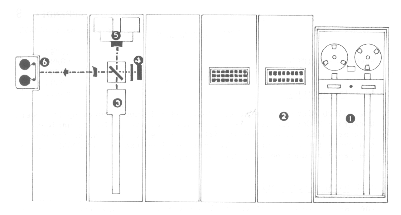
These are as follows:
The operation of an SD4020 camera is basically different from that of a standard camera in that an SD4020 camera tends to have its shutter open most of the time. An SD4020 instruction requesting a line to be drawn on the Charactron tube will cause the line to appear for sufficient time to sensitize the film in the camera (with its shutter open). A complete scene on a microfilm frame is therefore built up by a large number of lines and characters appearing on the Charactron tube for short periods of time. At no time is the complete scene available on the tube face.
A diagram of the tube is shown in Fig A9.2. As far as line drawing is concerned, the Charactron tube behaves very similarly to the standard cathode ray tube. Fig A9.2 shows how a character is projected on the viewing screen. The electron gun shoots an unshaped electronic beam towards the viewing screen. The beam passes through selection plates which deflect the unshaped electronic beam through the particular matrix aperture for the desired character. As the beam leaves the matrix, it has been shaped into the form of the character aperture through which it has passed. This shaped beam is then accelerated and then deflected to the desired position on the tube face. The character matrix is a small thin alloy disc on which 64 character shaped openings are engraved in an 8 × 8 array. The whole matrix is less than 0.25in square.
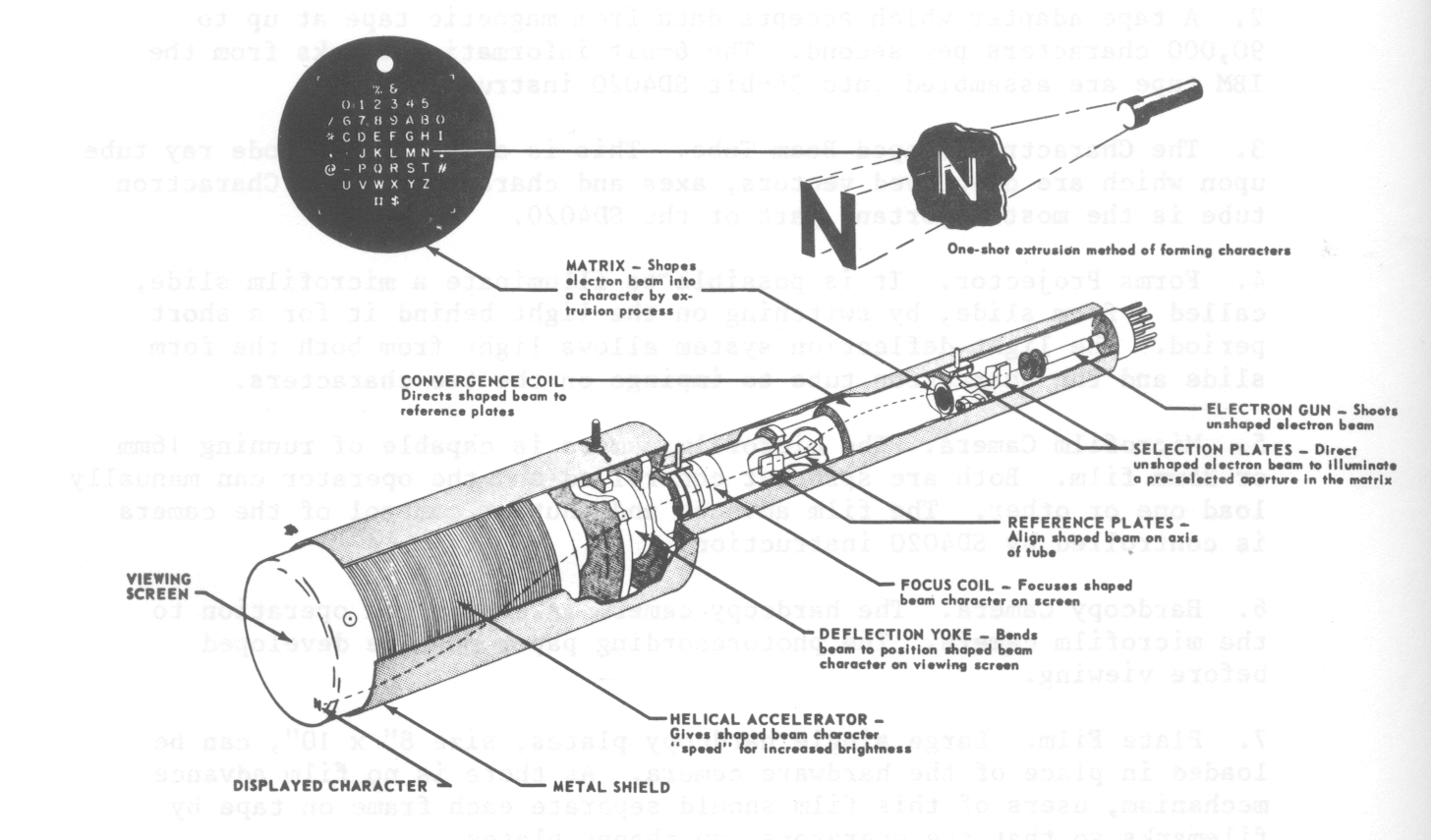
As far as line drawing is concerned, the screen is divided into 1024 × 1024 positions and the beam can be deflected so that a line can be produced between any two of the raster positions. Each Charactron character occupies approximately 6 horizontal by 9 vertical raster positions on the plotting area of the tube face.
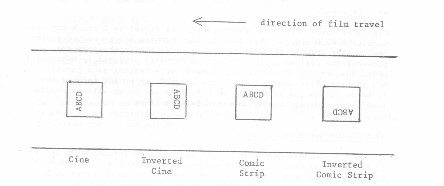
The complete Charactron tube assembly can be manually moved through 90°, 180°, 270°. Its standard setting is the CINE postion shown in Fig A9.3. The other positions of the tube are also shown in Fig A9.3. This manual movement of the tube is not a trivial operation. Consequently,plotting at the Laboratory will always be in CINE mode unless another tube position is specially requested.
35mm and 16mm film is available at the Laboratory. The 16mm film will normally be mounted. This is perforated and is ideal for producing movies direct from the SD4020. The 35mm film is also perforated. The film can be used in aperture cards or 35mm roll viewers. The image is compatible with standard 35mm movie projectors. The camera operates at speeds up to 10 frames per second and is supplied with two take-up and two supply magazines.
The hard copy camera makes it possible to record the displayed information on photo recording paper. The paper is in a continuous roll approximately 9 3/8in in width. The 4in square display on the Charactron tube is recorded as a 7.5in square on the paper. The standard pull down between frames is about 99.5in. The magazine holds about 350 feet of paper. Once a suitable amount of output has been produced on the SD4020, the hard copy magazine is removed and developed off-line from the SD4020.
This feature allows the SD4020 to superimpose fixed data on the variable data generated by the Charactron shaped beam tube. The fixed data is produced on a glass slide (for example maps and drawing formats). The glass slide is then mounted in a slide holder assembly which is inserted into the form projector. A strobe light located within the form projector is used to illuminate the glass slide. The strobe light is flashed under program control to cause the slide data to be superimposed on the information coming from the Charactron tube. Alternatively, by energising a special AUTO-FORM PROJECT switch, a form may be projected automatically for each frame advance.
Graphical output from the SPROGS package is stored on 7-track magnetic tape as SD4020 orders. This tape is then removed and remounted on the SD4020. The SD4020 tape adapter then decodes the information and produces the desired output. Output is normally produced in odd parity mode. However,the SD4020 is also capable of accepting even parity BCD records. Even parity records are assumed to be BCD information to be output as characters and such records are typed with automatic line feeds and page throws inserted between frames.
Appendix 10 defines the SD4020 order code and the format taken by the 36 bit instructions. The raster positions run from 0 to 1023 in both directions. The origin (0,0) is in the upper left hand corner with X and Y values increasing to the right and down, respectively.
The SD4020 instructions refer to these raster positions. The following section will describe each of the SD4020 operations. The opcode of each instruction is given in brackets following the instruction name. The names in the next section are those used in Appendix 10. The complete set of all SD4020 commands are described here, although a number of these cannot be used directly from SPROGS.
For all the operations given above, the SD4020 accepts 36 bit instructions one at a time, decodes them and produces the required action. This is the normal mode of working. However there is also a typewriter mode of working. Once this mode has been selected, hardware characters are generated more economically as far as both time and space are concerned. The typewriter mode is initiated by either of the two commands TYPE SPECIFIED POINT or TYPE CURRENT POINT.
The SD4020 character. numbered C, is typed at the raster position (X,Y). In addition the typing position is moved to the next character position. In the typewriter mode, the raster grid of 1024 × ]024 positions may be regarded as consisting of 64 lines of 128 typing positions. Once typing mode has been entered by the TYPE SPECIFIED POINT instruction, characters are typed across the line until the 128th space has been filled or a CARRIAGE RETURN character is typed. In either case, typing continues on the next lower line at the extreme left of the grid (X = 0, Y = Y + 16). An ADVANCE FILM instruction must be given after the 64th line has been typed. Otherwise typing will continue on the first line of the same frame at X = 0, Y = 0 and will be superimposed on any information already there.
After the SD4020 has entered typewriting mode, each subsequent instruction of 36 bits is divided up into six 6-bit fields as shown in Format 7 (Appendix 1Otyping position is then incremented. Each 36-bit instruction in typewriting mode therefore types 6 characters. The characters Ci can be any of the characters defined in Appendix 6, except that the character codes 12, 52 and 56 octal do not type characters but act as carriage and mode controlling operations.
Ci = 12 will cause the rest of the instruction to be ignored and returns the SD4020 from typewriter mode to normal mode.
Ci = 52 will cause the carriage control to move to the next line (X = 0, Y = Y + 16).
Ci = 56 is similar to the RESET instruction. Any remaining characters in the word are ignored.
As the character 12 can also appear in the first character position, this could be considered as a special SD4020 order for resetting the normal mode of operation. This is given the name STOP TYPE (see RESET).
If at any time the SD4020 encounters a record on the IBM tape which is even parity instead of the normal odd parity, then it enters a completely distinct mode of operation called PRINT MODE. In PRINT MODE, the SD4020 can be used for producing output equivalent to standard lineprinter output produced from BCD coded even parity files on a computer such as the IBM 1401. Within the PRINT MODE there are two sub-modes called PRINT NORMAL MODE and PRINT LIST MODE. The submode can be selected by the SD4020 operator. At the Laboratory, the SD4020 will normally be set to PRINT NORMAL MODE.
In this mode the first character of each record is interpreted as a control code to allow carriage control command to be fulfilled. The remaining 6-bit characters in the record are converted, the second character in the record being printed in the first character position of the line. The possible control characters in the first character position are:
When the 64th line of a page is reached, the SD4020 executes an automatic advance frame on the next carriage return. In positions other than the first, the BCD code 12 will cause the remainder of the current record to be ignored. Similarly the BCD code 56 will be equivalent to the RESET operation in typewriter mode except that the SD4020 will stay in PRINT MODE. In PRINT NORMAL MODE records of up to 132 characters can be processed.
This Appendix is a copy of the order code page.
The following routines provide histograms, shading, curve drawing, etc:
| Routine | Meaning |
|---|---|
| Histograms | |
| HSTGMA | Single shaded histogram |
| CMHSTA | Composite shaded histogram |
| Shading | |
| TXTURA | Shading rectangular area |
| Curve Drawing | |
| CVFNCA | Single valued function plot |
| CVFNCB | |
| CVFNCR | |
| CVFNCS | |
| ARCB | Arc of a Circle |
| ARCR | |
| ARCS | |
| CIRCLA | Complete Circle |
| CIRCLB | |
| CIRCLR | |
| CIRCLS | |
| ELLPSA | Complete ellipse |
| ELLPSB | |
| ELLPSR | |
| ELLPSS | |
| Contour | |
| CNTOUR | square grid contours |
| CNTOR1 | Contours inside specified boundary |
| Graphs | |
| AXESA | Plot axes |
| GRATA | Graticule over plotting area |
| SCALA | Label axes |
| Miscellaneous | |
| AROWHR | Arrow heads |
| CAROWVR | |
| BOXA | Rectangle |
| BXR | |
| READXY | Read current position |
These routines are described in more detail below:
      DIMENSION DZ (YMAX,CMAX), DYAR (YMAX*CMAX)
      EQUIVALENCE (DZ(1,1),DYAR(1))
Each histogram in this example would be contained in DZ(1,N) to DZ(YMAX,N). TYPE is a single
dimension array, specifying the type for each histogram in the set. Similarly, DX,DY are single
dimension arrays. Any negative Y values encountered in a histogram are taken as 0.M(1) = count of boundary points M(2) = not used M(I) = X, Y coordinates of boundary points in order M(I+1)These two routines expect output devices and a font to be set up and selected, together with the appropriate text scaling (suggested value for scaling fonts 1 and 2 here is XN/1023). The current region limits are reset to (0.0,0.0,XN,XN).
| 0.0 | no pattern |
| 1.0 | horizontal lines, DY apart |
| 2.0 | vertical lines, DX apart |
| 3.0 | combination of 1 and 2 |
| 4.0 | diagonal lines, angle to horizontal THETA where TAN (THETA) = DY/DX |
| 5.0 | diagonal lines, angle to horizontal THETA where TAN(π - THETA) = DY/DX |
| 6.0 | combination of 4 and 5 |
| 7.0 | horizontal dashed lines, DX long, DY apart. |
| 8.0 | as above, but every other line displaced by DX |
| 9.0 | vertical dashed lines, DY long, DX apart |
| 10.0 | as above but every other line displaced by DY |
The SPROGS macro, which makes use of the TASK system designed at ACL, allows a user to compile and run a FORTRAN job together with the SPROGS graphics package. The macro may be OBEYed, in which case a background job is initiated, or may be called from a RUNJOB command. The following parameters are available.
#MT1                   work tape, usually 9~track
#MT1 MYFILE            magnetic tape file
#MT1 (MYTAPE)          magnetic tape called MYTAPE
#MT1 (7172 ,MYTAPE)     magnetic tape number 7172 called MYTAPE
If the user specifies ? as the magnetic tape number, a pool tape will be obtained, a GETONLINE command instead of an ONLINE will be obeyed and the tape will be renamed. The user must have a magnetic tape budget which allows at least one more tape to be acquired, otherwise no tape will be allocated and an error will be indicated. For example:
#MT1(?,MYNEWTAPE)(WRITE)obtains a pool tape, GETONLINEs it and renames it MYNEWTAPE.
#MT14(?,FILMTAPE(PRTRACK7)) (WRITE)obtains a 7-track pool tape, GETONLINEs it, renames it FILMTAPE and WRITE qualifies it. The number of the magnetic tape used is given in the monitor file. Suppose, for example, it is 7000203. To use this tape again for SD4020 output, the user need only specify the tape name, the tape number, or both, with or without property.
#MT14 (FILMTAPE)(WRITE)
#MT14 (7000203)(WRITE) .
#MT14 (7000203,FILMTAPE(PRTRACK7))(WRITE)
all have the same effect. The user can specify a work tape by:
#MTI4 (?,!WORKTAPE(PRTRACK7))No magnetic tape budget is required, but the tape will not be preserved after it has been printed on the SD4020. The above format is the only way to ensure that a 7-track work tape is loaded.
#?? (OL *DA1(WRITE),(999 ,HYFILE))will ONLINE the exofile MYFILE with WRITE qualifier. Any commands specified in this way will be executed before all other peripheral assignments, which will take precedence if any stream conflict occurs.
PRINT listbefore taking any remedial action.
ENDJOB ALLBUT, COMMANDSHowever, if EJ (list) is specified, the macro halts:
ENDJOB listwhere list should contain a series of legal ENDJOB parameters.
SPROGS passes the user name and the job name to the user program as parameters 1 and 2 on the ENTER command (for use as frame identification when DVOUT is called for the first time for SD4020 selection). ENP allows the user to specify a list of parameters which will be added to the end of the parameter list used by SPROGS. Hence the first parameter in the list provided by the user will be the third parameter following ENTER. These parameters can be read by PERI type 60 orders (see ICL manual). The default program parameters are:
SEMICOMPILED (A)
LIBRARY (B)
PROGRAM (SPRG)
COMPRESS INTEGER AND LOGICAL
OUTPUT 12 = LP5
OUTPUT 13 = LP6
EXTENDED
ABNORMAL FUNCTIONS
OUTPUT `, (MONITOR) = LP0
END
The SPROGS semicompiled is held in two files, which are always the last two files presented to the consolidator.
XFIH and XPCH are used to compile and consolidate (unless the OPT parameter is used).
MT14 is used for SD4020 output. LP0 is used for tracing and monitor (but see SETIO command. LP1 is used for lineprinter graphical. LP5, LP6 are used for SD4020 operator instructions (but see SETIO command).
(1) A simple SD4020 job is contained in MYFILE
SPROGS *CR MYFILE,EJ
or
RJ MYJOB,:MACROS.SPROGS,*CR MYFILE,EJ
(2) No output to tape.
SPROGS *CR MYFILE,EJ,NOTAPE
(3) SD4020 job with card input and extra lineprinter output. Full monitor requested.
SPROGS *CR MYFILE, #CR1 MYDATA, #LP2 MYLIST,EJ()
(4) Compiler output and job output to same file. Optimising compiler required. Save binary job.
SPROGS *CR MYFILE,*LP MYLIST, #LP2 MYLIST,OPT,SAVE MYSAVED, EJ
(5) Binary program loaded. Extra ED file.
SPROGS RUN MYSAVED, #ED2 MYDISC,EJ
Note that, if a user wishes to run more than one SPROGS job from MOP at the same time, he should use the RUNJOB form for the second and subsequent jobs to avoid a jobname clash, since SPROGS will run the job as background with a predetermined name if called from MOP.
There are two levels of errors in the SPROGS system: expected and unexpected.
An error detected by the SPROGS routines themselves will normally generate an error message on the error output stream. If it is possible to recover from the error, the message is tagged NON-FATAL, and the program continues. Fatal errors lead to:
PAUSE EX
following a call to ENDSPR to close any magnetic tape used.
There are a number of other halts in the SPROGS system. These occur in places that should not be reached by the code, and indicate either a serious error, or an attempt to access a facility that has yet to be implemented. The current halts are:
In the PLAN routines:
