
The CASS (Computer Aided Sound Synthesis) package is provided to make soundtracks synchronised to computer generated films or to generate musical output from the computer. The programs are available on the Atlas PDPI5. The VCS3 synthesizer, further details of which can be found in the User's Guide, is used to realise the sounds. The package is data driven and is basically a two-pass system. The first pass reads in the data, calculates values for the synthesizer for each clock pulse (a 50 Hz clock is used) and writes them on to a magnetic tape. The second pass reads the data back from magnetic tape and outputs it to the synthesizer in real time. Two passes are necessary because the calculations for the values for a clock pulse may take more than 20 milliseconds (1/50 second). If this happens in real time one or more clock pulses would be missed. This is only likely to occur in very complex cases and a real-time single-pass version of the package which is capable of handling simple cases may be made available in the future.
The data for the system is usually read from a file on the PDP15 disc. The data, which can be free format, would normally come from the host graphics computer as an ASCII file. Data generated on the Atlas 1906A may be transferred to the PDP15 via the BSI link. It can, if required, be typed in at the PDP15 or be the output of another program on the PDP15.
The data for CASS must be in chronological order. If the user's data is not already in this form a sorting program is available which can be used to preprocess the data. Repeated sections of the data, such as a chorus, for example, may be defined as rhythms (macros) and be obeyed at any point during execution. This rhythm expansion facility is also a preprocess and must be followed by the sorting program.
The sound is usually referred to as music in the text and the standard musical notation has been adapted for some parameters. This was done because it is the notation for describing sound with which most people are familiar. If it is required, new key indexes may be implemented which have the frequency, in say Hertz, as the parameters. Users' suggestions for new key indexes are welcome.
Since the whole package is data driven, the data structure is very important. The data file, the only input to the package, is composed of a series of records, each record being made up of five data items as follows:
| Data Item | Name | Use |
|---|---|---|
| 1 | KEY INDEX | Determines exactly what this record will be used for (see Section 3) |
| 2 | TIME | The absolute time, in user defined units, since the star of the piece that the action defined in the current record will start or zero. If it is zero, the start time will be the end of the last event for this key index or the current time, whichever is the later (see Section 5) |
| 3 | DURATION | The length, in the user's time units, that the action in the current record will take. If it is zero then the action is instantaneous (see Section 5) |
| 4 | VALUE | The use of VALUE is dependent on KEY INDEX, eg, for a note, it contains the pitch of the note (see Section 3) |
| 5 | ENVELOPE INDEX | Determines which shape of envelope will be used for the action defined in the current record where appropriate. If no envelope is being used, ie 0, the duration should also be 0 (see Section 6) |
The actual record is spread over two lines and is made up entirely of integers.
| KEYINDEX | TIME | ||
|---|---|---|---|
| DURATION | VALUE | ENVELOPE INDEX | |
The actual fields are in free format and separated by commas. However, there are some maximum field width specifications as follows:
| Field | Maximum No. of Digits |
|---|---|
| KEYINDEX | 2 |
| TIME | 6 |
| DURATION | 6 |
| VALUE | 4 |
| ENVELOPE INDEX | 1 |
Thus a typical data file might look like this:
11.0           Set tempo
0,120,0
2,0            A note for Note 1
2,7,3
2,2                   "
4,0,3
2,6                   "
2,8,3
1,8            Terminator
0,0,0
The following table lists the currently implemented Key Indexes and is followed by the interpretation of the value parameter for each key index.
| KEY INDEX | USED FOR: |
|---|---|
| 1 | Terminator (NB: a terminating record must be included in every piece) |
| 2 | Note 1; a note for oscillator 1, OUTPUT CHAN 1 |
| 3 | Note 2; a note for oscillator 2, OUTPUT CHAN 2 |
| 4 | Filter frequency |
| 5 | Reverberation mix |
| 6 | Oscillator 1 frequency |
| 7 | Oscillator 2 frequency |
| 8 | Oscillator 3 frequency |
| 9 | Output channel 1 volume |
| 10 | Output channel 2 volume |
| 11 | Tempo |
| 12 | Filter frequency |
| 13 | Reverberation mix |
| 90-99 | Rhythm expansion |
The following notes give further details about each key index.
1. Only the first 2 parameters are relevant for a terminating record. The time should be given absolutely, ie not as 0, if the data is to be sorted.
2,3. The value, parameter 4, is the frequency of the note to be played (see Section 4). The envelope selected will control the volume for the duration of the note. The volume will start and end at 0, except for envelope 9, and its maximum will be the default or the last value set by key index 9 or 10 respectively.
4. The value, parameter 4, controls the centre frequency of the synthesizer band pass filter unit. This is not calibrated so the value can be in the range 0 to 4095. A value of 4095 will give a very low band pass filter and 0 a very high band pass filter. The default is 2048.
5. The value, parameter 4, controls the mix of the reverberation unit of the synthesizer. A value of 4095.gives 0% mix, ie, untreated sound, and a value of 0 gives 100% mix, ie reverberated sound only. Intermediate values give a mixture of the original sound and the reverberated sound. The default is 4095.
6, 7, 8. The value, parameter 4, is the frequency for the appropriate oscillator in the range -30 to +50 (see Section 4). The defaults are 0, ie, middle C. The envelope index, parameter 5 if used, will apply the envelope to the frequency value. This is not the same as key indexes 2 and 3 in which the envelope is applied to the volume value. It is advised that Key Index 6 should not be used at the same time as Key Index 2 and Key Index 7 should not be used at the same time as Key Index 3 since they could be sending different values simultaneously to the same oscillators. The effect is undefined.
9,10 The value, parameter 4, is the volume for the appropriate output amplifier and should be in the range 0 to 4095. A value of 0 is inaudible and 4095 is loud. The default is 3000. It is advised that Key Index 9 should not be used at the same time as Key Index 2 and Key Index 10 should not be used at the same time as Key Index 3 since they would be sending different values simultaneously to the same output channel amplifiers. The effect is undefined.
11. See Time Unit (Section 5).
12. As for Key Index 4 (filter control) but the value, parameter 4, is encoded in the same system as for notes and oscillators (Section 4).
13. As for Key Index 5 (reverberation mix) but the value, parameter 4, is the percentage of reverberation mix required.
90-99 See Rhythm Expander (Section 9).
In order to ease the coding of pitches of notes, the above system of discrete pitch coding is used. Middle C is represented as 0 and any pitch change is evaluated counting the number of semi-tones above or below middle C. Ideally, this scale reaches infinity at both ends, but for synthesizer purposes the range should be restricted between +50, -30.
Thus the F immediately above middle C has the code 5, then D# has the code 3; similarly, the note E below middle C has the code -8. The C above middle C is +12 and the C below middle C is -12.
This code should be used for any record involving control of an oscillator frequency, viz those records with a Key Index of 2, 3, 6, 7, 8, 12.
The time unit, used for both the duration of a particular action, eg a note, and the time that the action will commence, is defined by the user. It is suggested that the following method is used to determine the time unit.
The piece of music to be created should be looked through, and the note, or other desired action, which has the smallest length of time should be assigned the time value 1. Henceforth, all other actions should be integer multiples of this time unit. If this is not so then an even smaller time unit should be chosen until it is so.
For example:
  smallest note is a quaver so assign time unit length 1
  next note is a crotchet so time unit length is 2
  next note is a minim so time unit length is 4 etc.
In order to get the user's time units interpreted as notes of real time length, a tempo record should be included at the start of each piece of music as follows:
KEY INDEX                = 11
TIME                     =  0                    11, 0
DURATION                 =  0                    0,N,0
VALUE                    =  N
ENVELOPE INDEX           =  0
where N is the number of user-defined time units required per minute; the default is 600.
For example:
Suppose a piece of music is marked crotchet = 50 and the smallest note in the music is a semi-quaver, then the semi-quaver will be assigned the time unit 1, thus the crotchet will be assigned the time unit 4, thus the tempo setting, ie N will be:
4 × 50 = 200
Normally, no envelope would be used when setting the tempo. However, it is possible to change the tempo gradually by using an envelope, most likely envelope 9. The difficulty arises in the meaning of the duration, parameter 3. The end time is computed as (start time + duration) × old tempo at the start time. This end time remains fixed throughout the period of the envelope, even though the tempo is changing. Thus a note, say, or sequence of events with the same duration and start time as a record to change the tempo gradually will not finish at the same time as the tempo change.
If the time, parameter 2, of a record is 0 the start time will be the end time of the last event for this key index or the current time, whichever is the later. This is a relative time mode, ie in a series of events for a given key index each event is relative to its predecessor. Until the user is familiar with both the absolute time method of specifying start times and the relative time method it is unwise to mix the two methods.
The following example consists of 3 consecutive notes for Note 1. The first is specified absolutely and the other 2 are specified relative to their predecessors.
2,20               Absolute start time 20
4,1,1
2,0                Starts at time 20+4=24
6,2,1
2,0                Starts at time 24+6=30
4,3,1
This method of specifying the start time relatively cannot currently be used with the sort program and so cannot be used with the rhythm expander.
The envelope is the overall shape of the value of the note. By using different envelopes the user may vary the type of sound that a particular note makes. If the envelope index is zero then the action is instantaneous and so should have a duration of O.
The envelope shapes defined in the program are as follows:
If the duration of a record is not zero and the envelope index is in the range 1-8, the value of the parameter being controlled, eg volume, will be the same at the start and the finish. A permanent change in a parameter can only be achieved by a record with a duration of 0, ie, instantaneous change, or an envelope index of 9, ie gradual change. For notes, Key Indexes 2 and 3, the volume always starts and ends at 0 and uses a previously set value for the appropriate maximum volume. For other key indexes, the synthesizer parameter starts at the existing value, rises or falls to the new value specified in parameter 4, holds that value and then falls or rises back to the existing values.
It must be stressed that the actual setting up of the Synthi in conjunction with CASS depends entirely on the users' requirements (see VCS3 User Guide). However, there are a few standard options listed below:
| Option | Key Index | Synthi Devices | Patch |
|---|---|---|---|
| Note 1 | (2) | Oscillator 1, output channel 1 | A3 |
| Note 2 | (3) | Oscillator 2, output channel 2 | C4 |
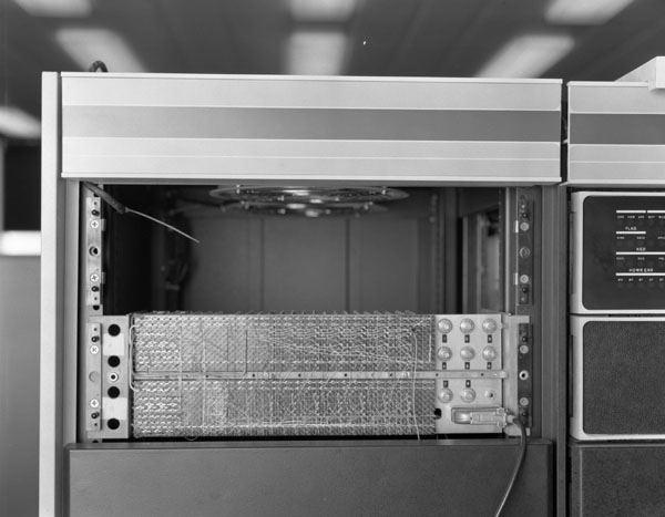
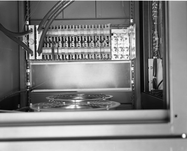
The actual connection between the PDP15 and the Synthi is made as follows. The eight DAC's which control the Synthi are located in the left-most cabinet of the PDP15. At the top of this cabinet, on the front panel, are two press-on covers. The lower of these covers should be removed exposing some electronics. To the right of the wiring is a standard 25-way cinch connector socket. The Synthi lead should be plugged in here with the cable from the plug running to the right. This cable leads to a small white plug box - more information on the plug box is given below. Coming out of the plug box are two leads which connect to the Synthi. The large edge connector plugs into a socket on the front of the Synthi with the lead running to the left edge of the Synthi. The 8-way Jones plug connects to a socket on the back of the Synthi.
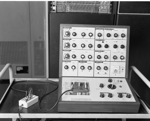
The plug box enables any of the eight DAC's to control any of the devices on the Synthi. The bottom row of holes, numbered 0-7, are the DAC outputs, and the top two rows of holes are lettered A-R and represent the columns of the patch board. The plug box like the synthi needs to be set up before playing music. Also like the Synthi the plug positioning depends on the users requirements but the CASS system assumes the following connections:
| Plug box - bottom row | Plug box - top row | Device Controlled |
|---|---|---|
| 0 | M | Reverb mix |
| 2 | O | Vol Ch 1 |
| 3 | P | Vol Ch 2 |
| 4 | N | Filter frequency |
| 5 | I | Frequency Oscillator 1 |
| 6 | J | Frequency Oscillator 2 |
| 7 | K | Frequency Oscillator 3 |
The blue dials controlling the oscillator frequencies should be set to their mid-positions, marked 5, the white dials controlling the volumes of the output channels should be set to their minima, marked 0 and at least one of the white dials controlling the output waveforms from the oscillators should be set above 0, say 5. If the filter or reverb units are being used, the frequency or mix dial respectively can be set to zero. The above settings are by no means mandatory but are recommended as a basis from which to experiment. The control output from the PDP15 can be thought of as an offset to the setting of the appropriate dial on the synthesizer or vice versa since the control voltage and the dial setting are effectively summed.
Note: the conventions shown below are used 1n the next 3 sections.
| SYMBOL | USED FOR |
|---|---|
| CR | CARRIAGE RETURN |
| ALT | ALTMODE KEY or ESC |
| CTRL | When shown before an alphabetic character the CONTROL key should be depressed simultaneously with the character, eg, CTRL C represents the control and C keys. |
| SP | SPACE |
| EXAMPLE | The replies from the computer are emphasised |
The user's data file should be on the PDP15 disc. If it is not on the disc, then the system program PIP should be used to transfer the file. The file CASS Bin, to be found on DECtape 2300 (located near the PDP15) should also be transferred to the disc (again using PIP).
The program should then be loaded, using the system loader. The user types:
LOAD CR
to which the system replies:
            LOADER V3BOOO


            >
the user then types:
¬ CASS (A)
and the loader starts to load the program into core. When the loading is complete, the loader will output:
CTRL S
to which the user replies with:
CTRL Q
The system will then return to DOS.
8.2.1 Before running CASS, the mag tape SYNTHI TAPE #1 (located by the PDPI5) should be mounted on the right-hand mag tape unit. The tape should be run forward to LOAD POINT, on-lined and the unit number set to 2.
8.2.2 The program is started by the user typing:
GETS CR
If CASS does not reply then CASS should be re-loaded (see 8.1).
8.2.3 CASS will then ask the user if compile and play is required or replay only. Compile and play means that the user's data file will be read in and CASS will compile a new binary file on the mag tape, over-writing the present contents of the tape. Replay only means that the program will only play the previously stored binary file on the mag tape, and not compile a new binary file from users data. (If replay only is required see 8.2.5 onwards).
8.2.4 For Compile and Play the user will be requested to type in the filename of the data file. The full nine characters of the filename should be entered, eg:
  for file TUNES1 SRC enter    TUNES1SRC  CR
  for file A SRC enter         A     SRC  CR
CASS will then start to process the user's data file and at the same time produce a binary file on mag tape. This process may take only a few seconds, or several minutes, depending on the length of the user's data file.
8.2.5 When the processing of data is complete or replay has been requested, the tape will rewind and the program will pause. At this point:
PAUSE 1
will be output to the teletype. When the user is ready to listen to the sounds stored on the tape:
CTRL P
should be typed on the keyboard. The tape will now be played in real time through the Synthi.
At the end of the piece of music the program will return to DOS. If it is desired to re-run the program then follow instructions from 8.2.2 onwards.
The need sometimes arises to repeat a sequence of actions, eg notes, one or more times in a piece of music. The rhythm expander was written so that the user would not have to manually repeat action in his data file.
Supposing a user wishes to repeat a series of, say, notes. The rhythm expander program should be used as pre-process to the CASS system. The user should flag the notes so that they may be inserted at the required place in the data file.
A rhythm is a series of notes or actions which will be repeated one or more times in a piece of music. The definition is made as follows:
                90,0             KEY INDEX = 90       .'.  DEFINITION OF
RYTHM NUMBER®   1,O,O ¬  0     INDICATES START           RYTHM
                2,0
                2,5,3
                2,2.             THREE NOTES FOR NOTE 1
                4,7,3
                2,6
                2,0,3
                90,8             KEYINDEX = 90, TIME = 8
RYTHM NUMBER®  1,0,1 ¬ 1 INDICATES END OF RHYTHM DEFINITION
The series of notes to be repeated are actually stacked in the program, in this case the 3 notes. The notes are sandwiched by two special records. These records must have a key index of 90. The first record will have a time of 0 and the last record will have a time value equal to the length of the rhythm, in the users time unit, in this case 8. The rhythm number is used to identify a particular rhythm, up to 9 different rhythms may be stored. The envelope index field is used to check the start and end of rhythm definitions. It must contain a 0 in the first record and 1 in the last record. RHYTHM DEFINITIONS MAY NOT BE nested in any way. If more than one rhythm is required then it must be defined separately, eg:
                        ----
                        90,240       END OF PREVIOUS DEFINITION
Just finished Rythm3®  3,0,1
                        90,0         START OF NEW DEFINITION
Just starting Rythm7®  7,0,0
                        ----
A rhythm is not put in the output file until it is played.
A rhythm definition may contain a call to a previously-defined rhythm.
To play a rhythm the following record is used:
   A, B
   C, D, O
where:
| A | the KEYINDEX is 90 + the rhythm number eg, to play rhythm 3 then the KEYINDEX is 93. |
| B | the Time is the time that the rhythm will start in the data file. |
| C | the number of times the rhythm is to be repeated. |
| D | any notes in the rhythm, ie, records with a key index of 2 or 3, will be shifted in pitch up or
down by the value D. This is on the same pitch scale as the notes used, eg, if D = 0 then the rhythm
will be repeated C times as it was defined.
If D = 5 then any notes in the rhythm will have their pitch changed ie, 5 added to it. D may be positive or negative. |
A call to play a rhythm, a record with a KEY INDEX between 91-99, may be placed inside a rhythm definition, ie, it is possible to nest rhythm calls. Nesting may be up to 5 deep and the rhythm called must be other than the calling rhythm.
The rhythm expander program binary is in the file BRYTHM BIN also on DECtape 2300. It is loaded in the same way as CASS. Alternatively, when the loader replies with CTRL S the user may type CTRL S. The program will then request the name of the file to be processed. This is typed in, in the same format as for CASS. The program then reads the user's data file from the disc and creates a temporary file for the output which will consist only of CASS executable records. This temporary file is then renamed with the input filename, thus overwriting the original data. The Sort program should now be run.
This program sorts the user's data file into Time order. It should always be used whenever the RHYTHM EXPANDER is used, before presenting the data file to CASS. It can also be used to sort any data which is not already in chronological order. It should not be used if the relative time mode has been employed (see Section 5).
The Sort program works in the same way as the rhythm expander program (9.3). The program binary is in the file BSORT BIN which is also on DECtape 2300.
