Contact us Heritage collections Image license terms
HOME ACL Associates Technology Literature Applications Society Software revisited
Further reading □ OverviewCASS manualVCS3 sound synthesizer
ACD C&A INF CCD CISD Archives Contact us Heritage archives Image license terms

Search

   
ACLLiteratureICL 1906A manualsCASS
ACL ACD C&A INF CCD CISD Archives
Further reading

Overview
CASS manual
VCS3 sound synthesizer

User's Guide to the VCS3 Synthesiser

1. INTRODUCTION

VCS3

VCS3
Full image ⇗
© UKRI Science and Technology Facilities Council

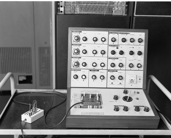
The VCS3 is a sound synthesizer made by Electronic Music Studios (London), (EMS). A sound synthesizer is used to synthesize or build up sounds from basic wave forms. In order to use the Synthi it is not necessary to be a musical genius, but those users with some form of musical knowledge may have some slight advantage.

The Synthi is a complex piece of electronics, built up from several independent devices. It is capable of performing several difficult tasks, but it is suggested that the user becomes familiar with each individual device before attempting more complicated production of sounds.

Note: when the Synthi is first switched on it may take 10-15 minutes for the electronics to become stable. However, even this stable may be inclined to slow change over a period of time.

THE SYNTHI: FIRST IMPRESSIONS

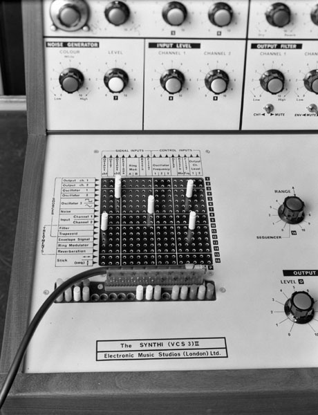
The synthesizer is divided into two panels - top and bottom. On the bottom panel at the left-hand side is a 4in black square with a 16 × 16 matrix of holes in it. This square is very important to the synthesizer and is called the PATCHBOARD. Just below the PATCHBOARD are a number of small jack plugs called PATCH PINS.

To the right of the PATCHBOARD is a black cone with a stick emerging from its centre. This is called the STICK and its action is not unlike a pilot's joy stick in an aircraft; ie, it is anchored at the base, and the top is free to move in two directions simultaneously.

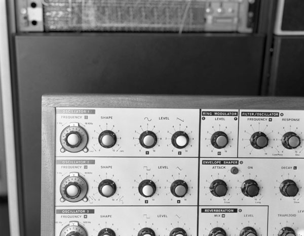
The rest of the bottom panel, and most of the top panel is covered in dials of different colours, the basic code of which is given below.

DIAL COLOUR CODE

WHITE
All white dials are used to control levels, almost all of which are volume levels.
BLUE
All Blue dials control a frequency of one form or another (note: only devices with a blue dial in them may be used as internal sources).
YELLOW
All Yellow dials control filters or the type of filters involved.
RED
All Red dials are connected with the envelope shaper device.
GREEN
All Green dials are controls which have a direct but independent effect on the waveform being processed.

VCS3 Dials

VCS3 Dials
Full image ⇗
© UKRI Science and Technology Facilities Council

3. THE PATCHBOARD

OUTPUT CHANNEL 1 2 OSCILLATOR 1 OSCILLATOR 2 OSCILLATOR 3 NOISE INPUT CHANNEL 1 2 FILTER TRAPEZOID ENVELOPE SIGNAL RING MODERATOR REVERBERATION STICK OUTPUT CHANNEL 1 METER OUTPUT CHANNEL 2 ENVELOPE RING MODULATOR A B REVERBERATION FILTER OSCILLATOR FREQUENCY 1 2 3 DECAY REVERB MIX FILTER FREQ OUTPUT CHAN LEVEL 1 2 1 2 3 4 5 6 7 8 9 10 11 12 13 14 15 16 A B C D E F G H I J K L M N O P TREATMENTS SOURCES SIGNAL INPUTS CONTROL INPUTS

The Patchboard

All the individual devices in the Synthi are not connected together internally. In order to connect together the devices required, it is necessary to set up a PATCH. The PATCH is made by inserting PATCH pins in the PATCHBOARD. The PATCHBOARD is labelled A-P along the columns, and 1-16 along the rows. Thus A1 is the top left hole.

The train of thought is in at the left-hand side and out at the top on the PATCHBOARD. Thus, wherever a pin is situated on the board, the signal transmitted via the pin is coming in along the row that the pin is in, and going out up the column that the pin is in. Eg, if a pin is inserted at location A3 then the signal from Oscillator 1 (the input) is taken to output channel 1 (the output).

Devices may be linked into a train, eg, if a pin is inserted at H4, and another at A10 then this forms a train as follows:

It is important that the user distinguishes between signal inputs and control inputs. If one thinks along the following lines, then, with a little thought, problems can be averted.

  1. Interpret goes into for signal input.
  2. Interpret in charge of for control input.

Referring to the above diagram, the left-hand half of the patchboard is used for the signal inputs, and the right-hand side is used for the control inputs.

VCS3 Patchboard

VCS3 Patchboard
Full image ⇗
© UKRI Science and Technology Facilities Council

4. THE BASIS OF THE SYNTHESIZER

SOURCE TREATMENT OUTPUT

Diagram of Synthesizer Action

In order to obtain a sound from the Synthi, it is important that the conditions in the diagram are satisfied.

  1. Source: A source may be created from within the Synthi (eg an oscillator) or input to the synthesizer via a jack plug (eg a guitar or organ). The source is used as a base to which a treatment is applied.
  2. Treatment: A treatment is any function in the synthesizer which causes a change to the waveform of the source. It may be very simple (eg, merely volume change) or complex (eg ring modulated or a combination of effects). This is the only part of the circuit which may be omitted. (It is possible to plug a source directly out.)
  3. Output: Finally, it is very important that the resulting waveform is plugged-out. It is of no value, if the Synthi is producing a waveform that you cannot hear. The output may be to the speakers located in the sides of the Synthi or taken out to an external stereo amplifier or tape recorder, via the jack sockets. This is effected by the output channels (cols A and C of the patchboard).

Note: For a fuller description and use of the individual devices on the Synthi refer to:
The Synthi Educational Handbook by EMS. This is held by A H Francis in Room G23.

⇑ Top of page
© Chilton Computing and UKRI Science and Technology Facilities Council webmaster@chilton-computing.org.uk
Our thanks to UKRI Science and Technology Facilities Council for hosting this site