
Each of the main devices used by the SMOG system has a natural grid, or mesh, associated with it. Each cell in the mesh is separately addressable and no intermediate points may be so addressed. This imposes a discrete, cellular structure upon the output medium which limits the resolution obtainable. The total number of addressable cells on a device ranges from that for the lineprinter (120 × 120) to that for the FR80 (16384 × 16384) (see Appendix 5); a fancied resemblance between these (notional) meshes and the finely-ruled glass plates used by printers for photo-reproduction has resulted in the term "Raster" (German for Printing Screen) being applied to the set of addressable cells on a graphical output device.
Standard cine-film frames have their own aspect ratio and so the initialisation of a SMOG device usually results in the software or hardware masking of a portion of the total writing area and leads to the concept of a visible area in which writing and plotting may take place and appear on the output medium. Only on the Tektronix 4010, the lineprinter and the pen-plotter can the whole writing area, be used. (See Appendix 5.)
Note: Aspect Ratio: strictly an aeronautical term relating the length of a wing to its width. It has replaced the term "Picture Ratio" in Cine and Television contexts. Aspect ratio is now taken to mean the number: (Picture Width)/(Picture Height). For cine work it is about 4/3 - standards vary slightly. For television it is 5/4 but attempts to produce film for television using this value will fall foul of telecine apparatus which has a "Gate Cut-off" ratio of 4/3.
We can attach a natural coordinate system to the raster - namely the set of labels by means of which the cells are addressed. It is most convenient to use a number-pair to index a cell or "Raster-point" by column and row and to call these numbers the Device X and Y coordinates respectively but the abbreviation Raster coordinates will be used hereafter.
As an indication of the resolution obtainable on the main devices the following table shows, for each, the full addressable area in raster coordinates; the visible area will, of course depend upon which SMOG device is selected as an output channel.
Main Device     XMIN   YMIN     XMAX     YMAX
FR80              0      0      16383    16383
Tektronix 4010    0      0       1023      779
Lineprinter       0      0        119      119
Hewlett-Packard   0      0       9999     9999
The statement of a problem in the physical world involves an abstraction resulting in an analogue or model with some underlying mathematical structure. When it is decided that graphical output is required from a computer then the mathematical analogue becomes numerical. A scientific investigation by computer often has the form of a dynamic numerical system with rules of behaviour built in. The location of characters when writing text requires numerical specification of position etc. In all cases we must map from the "Space" of the problem (or of the idea) onto the strictly two-dimensional output medium. It follows that we must select in a uniform way certain points in "Problem space" (we cannot map them all) and identify these with certain raster coordinate numbers also in a uniform way. The SMOG routines LIMIT, LIMITV and LIMITS facilitate this process by performing the necessary scaling, translating and mapping to the raster coordinates of the chosen SMOG device. (See Section 3.4)
In the context of SMOG, a region is a window or aperture in a (virtual or actual) mask on a "Space". It is by means of the concept, "Region" that the necessary mapping to the graphical output medium is effected. By convention, Region 0 is the device mesh and Region 1 is the user's window on his "Mathematical space" - the space in which his problem is defined, or any conveniently defined set of points in a two-dimensional space of his choosing.
The user may change his frame of reference, as it were, many times during a run, plotting with respect to the coordinate system of his problem or with respect to the raster coordinates of the selected SMOG device by calling the following subroutines:
REGION(0.0)
JREGON(0)
this causes the system to interpret all coordinate numbers specified by the user as referring to the device mesh. Conversion to type INTEGER will take place and, where possible, actual mesh cells will be addressed. This interpretation will continue until the end of the program unless Region 1 is selected by the appropriate call.
REGION(1.0)
JREGON(1)
this causes the system to interpret all coordinate numbers specified by the user as being with respect to his own "Problem space". Positions will be taken as "User Coordinates" and subjected to the mapping processes described in Section 3.4. When a device is initialised by the calling of one of the subroutines - SMOG codenames - in table 2.1 (see Section 3.5) relevant masking is established, Region 1 is automatically selected and this setting prevails until Region 0 is explicitly selected by the user. The following commands are all interpreted as being with respect to the currently selected Region.
The possible output media and SMOG devices appear in table 2.1, the maximum writing area for each main device in table 3.1. In particular, the writing area on the FR80 is square but the choice of a SMOG device in the range 1 to 8 will invoke system routines that impose an aspect ratio upon the output medium different from the 1:1 ratio for the FR80 tube-face.
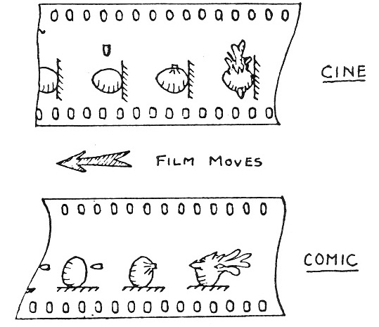
In general, 16mm and 35mm film for projection will have rectangular areas exposed but the provision is made for the abutting of adjacent frames so that strip-charts, for example, may be produced.
Two modes exist in which plotting may be performed on the FR80: cine mode and comic-strip mode. The effect of selecting comic mode is to rotate the plotting area through -π/2 and some adjustment may be made by the system to fit the new area into the visible area of the selected SMOG device - the details follow. On the FR80 each camera is fitted with an aperture1 plate which obscures some of the tube face but which allows film images to be larger than the standard cine frame. Software masking is employed to produce differently shaped standard areas. Six standard areas are defined for each device and selected by the SMOG system by calls to the following subroutines:
sets the visible area to be the maximum that camera masking allows.
sets the visible area to be sufficiently greater than the standard cine frame to allow continuous plotting across more than one frame. When a new frame is selected, no gap appears between it and the previous frame.
sets the visible area to be the standard cine frame aspect ratio, excluding the sound-track, with standard frame separation for the selected camera.
These set the same visible areas as their cine counterparts but in each case the picture is rotated -π/2 (ie 90°) with respect to the film. Also, the aspect ratio is inverted, since the width becomes the height and vice versa and thus the shape of the picture may change. This convention preserves the implied time sequence of successive frames whatever the mode. Full details of the visible areas are given in Appendix 5.
Note: Aperture: this should not be confused with the optical aperture-stop which is fixed; giving a constant f-number for each camera. The Aperture Plate is an external masking-plate which obscures part of the display area of the cathode ray tube face.
The user may at any time select comic mode by calling the subroutine:
This command generates an FR80 order instructing the plotting software to perform the transformations: (x,y) → (y,-x) if I=1 and the identity (x,y) → (x,y) if I=0. This is effected at the lowest instruction level and so is a "Pure rotation" of the frame on the film, if I=1, after any higher level software masking has taken place.. This means that:
      CALL CMAPER
and
      CALL APER
      CALL COMIC(1)
may be completely different in their effects. For example, if an equilateral triangle is drawn in CINE mode, the following diagram illustrates the difference between CMCINE and CINE,COMIC(1). The picture area is shown dotted.

If the hardcopy camera is being used in many-up mode, FRHCM, selecting COMIC mode will not only rotate the individual subframes, but will rotate the whole frame. Thus if the COMIC mode is changed while a complete frame of subframes is incomplete, overwriting can occur. The diagram shows the ordering of the subframes for the default 2×2 case for both CINE and COMIC mode.

In order to complete the mapping process the user must supply scaling information to the SMOG system. This is effected by his assigning numerical limits to Region 1 and indicating the subset of the raster points that he wishes to map to by calling one of the following subroutines:
      LIMIT(X1,Y1,X2,Y2)
      JLIMIT(IX1,IYI,IX2,IY2)
this identifies Region 1 with the whole writing area of the currently selected main device. The coordinate system defined by the pairs (X1,Y1) and (X2,Y2) is now established over the whole plotting area. The user should be aware of the possibility of writing out of the film-frame in this case. After initialisation (3.5), the coordinate system is set up to be from (0.0,0.0) to (1023.0,1023.0) by a call to LIMIT and Region 1 is selected.
Example:
CALL CINE
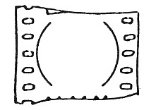
CALL LIMIT(-1.0,-1.0,1.0,1.0)
followed by instructions to draw the unit circle, centred upon the origin will result in the following output on film:
A more useful subroutine is:
      LIMITV(X1,Y1,X2,Y2)
      JLIMV(IX1,IY1,IX2,IY2)
this identifies (X1,Y1) with the lower left-hand vertex of the visible area on the selected SMOG device and (X2,Y2) with its upper right-hand vertex, scaling the rectangle linearly according to the subroutine arguments. The aspect ratio of the device must be kept in mind when the actual plotting is done - all that one is now sure of is that all points (x,y) for which X1<x<X2 and Y1<y<Y2 will actually appear on the output medium.
Example:
CALL CINE
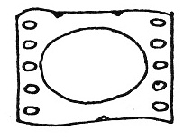
CALL LIMITV(-1.0,-1.0,1.0,1.0)
followed by instructions to draw the unit circle centred upon the origin will result in the following output on film:
Example:
      CALL CINE
      CALL LIMITV(-1.33,-1.0,1.33,1.0)
followed by the centred-up unit circle instructions will give a fairly true representation of a circle on the film. The scaling of the visible area has reflected the standard cine aspect ratio in this case:
It is possible to reset the aspect ratio on a given device, thereby setting up a new "Visible area" with prescribed scaling ratio by means of the subroutine:
      LIMITS(X1,Y1,X2,Y2,SX,SY)
      JLIMS(IX1,IY1,IX2,IY2,ISX,ISY)
this resets the aspect ratio of the visible area on the selected SMOG device using the values SX and SY. None of the succeeding plotting is obscured or lost since the new visible area is identified with the rectangle specified by (X1,Y1) and (X2,Y2). The effect of this subroutine is to reduce the visible area already set in either the X- or Y- direction by an amount sufficient to make the prescribed rectangle fit centrally into the "Old" visible area.
Example:
CALL CINE
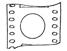
CALL LIMITS(-1.0,-1.0,1.0,1.0,1.0,1.0)
followed by the same instructions to draw the unit circle will result in a very good representation of the circle which just fits into the cine frame.
Diagrammatically, the effect is represented:
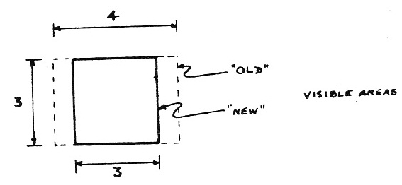
where integers are used to represent the aspect numbers. In this case (SX,SY) = (1.0,1.0) and the new visible area is the square that has one pair of sides in the corresponding sides of the rectangle defining the visible area before the call to LIMITS(A,B,C,D,1.0,1.0). The new "rectangle" is centred upon the old and the coordinate limits in the argument list are applied.
Note: This new visible area now becomes the "Old" visible area, should LIMITS (A,B,C,D,E,F) be called again with no other visible-area-defining call between. Thus a sequence of such calls with aspect ratios alternating >1,<1 will cause successive reduction of the visible area towards a central, small rectangle.
RASTER(X,Y)
This routine sets X and Y to the distance between raster points on the output device in terms of the units of the current region limits. It is useful for calculating line densities for shaded areas. For example, to shade an area 100 units wide and 500 units high in the current region limits with vertical lines every 12 raster positions.
      CALL RASTER(X,Y)
      N = 100.0/(12.0*X)
      CALL VECFAM(0.0,0.0,0.0,500.0,100.0,0.0,100.0,500.0,N)
Some measure of economy is effected in the SMOG system by loading only those subroutines that are explicitly present in the source coding. Selection of a SMOG device as an output peripheral - device initialisation - is effected by the calling of one of the following subroutines:
FRCL16
FRBW16
FRCL35
FRBW35
and so on. The subroutine name for the initialisation of each SMOG device is its SMOG Codename in table 2.1.
Example:
      CALL TKTRON
      CALL CINE
      CALL LIMITV(-1.0,-1.0,4.0,3.0)
This will route graphical output to the Tektronix 4010 storage-tube display, set the software masking so that the picture fits into a standard cine frame and attach a scale to the defined area. The first statement in the example is the device initialising subroutine and forms the "Left delimiter" for the graphical output in a given run.
Only one SMOG device may be initialised in any one run and it is evident from the opening paragraph that by using the SMOG Codenames as initialising routines the user seems to be committed to having a binary version of his program for each device that he may wish to use. This is overcome by calling the following subroutine at initialisation time:
DVALL(I)
This loads all the Main Device handling routines and selects device number "I" for the current run. Obviously, the device number can now be entered at run time. In order that the user may exclude from his program the routines for devices that he knows he will never need, he may call any of the following subroutines:
NOFR
NOTK
NOHP
NOLP
Example:
      READ(1,999)I
      CALL DVALL(I)
      CALL NOFR
This could be a part of a graphics program which is compiled and stored in local binary form for subsequent running. When the user runs the program the integer "I" will be read in on channel 1 and will determine which one of the three SMOG devices 9,10 or 11 (table 2.1) is to be used for plotting this job. The user must ensure that the value read in in this example is one of 9,10,11. Should "I" indicate a main device for which the handling routines have not been loaded, the macro (Appendix 2) will halt execution and send the message "HALTED XX" to the monitoring file. "XX" will be one of: FR, TK, LP, HP, indicating the device which is the object of the conflict.
NB There is no correspondence between SPROGS device numbers and SMOG devices.
