
The paper discusses the concept of graphical input and dialog from an user point of view, based on the structure of a graphic information system for storage, retrieval and handling of a large amount of graphical, non-graphical data and logical relationships between both. Therefore the basic ideas of the most important modules in such a system (syntax definition, user data structure and dialog monitor) are discussed in some detail. The concepts presented should be seen as a contribution to the discussion of the man-machine communication based on the experience with graphic systems for bulk data handling and for a mainly application dependent dialog.
There are basically two approaches for a discussion about the input to graphic systems: the one is the system view, the other is the user view. Both views have to be compatible and an unambiguous mapping between them has to be possible. This paper addresses itself to the user view and its interface to the system e.g. the interface to some sort of a graphic core system [1,2].
From a system point of view the following aspects should be discussed:
The aim should be as far as possible a symmetry between input and output primitives; the following table serves as an example for a conceivable I/O-symmetry:
| Output primitive | Input primitive |
|---|---|
| marker | locator |
| line | high-level primitive |
| string | keyboard |
| segment | pick |
| high-level primitive | valuator |
| non-existent | button |
The problems of such a symmetry concept lie in the efficiency and the size of its implementation.
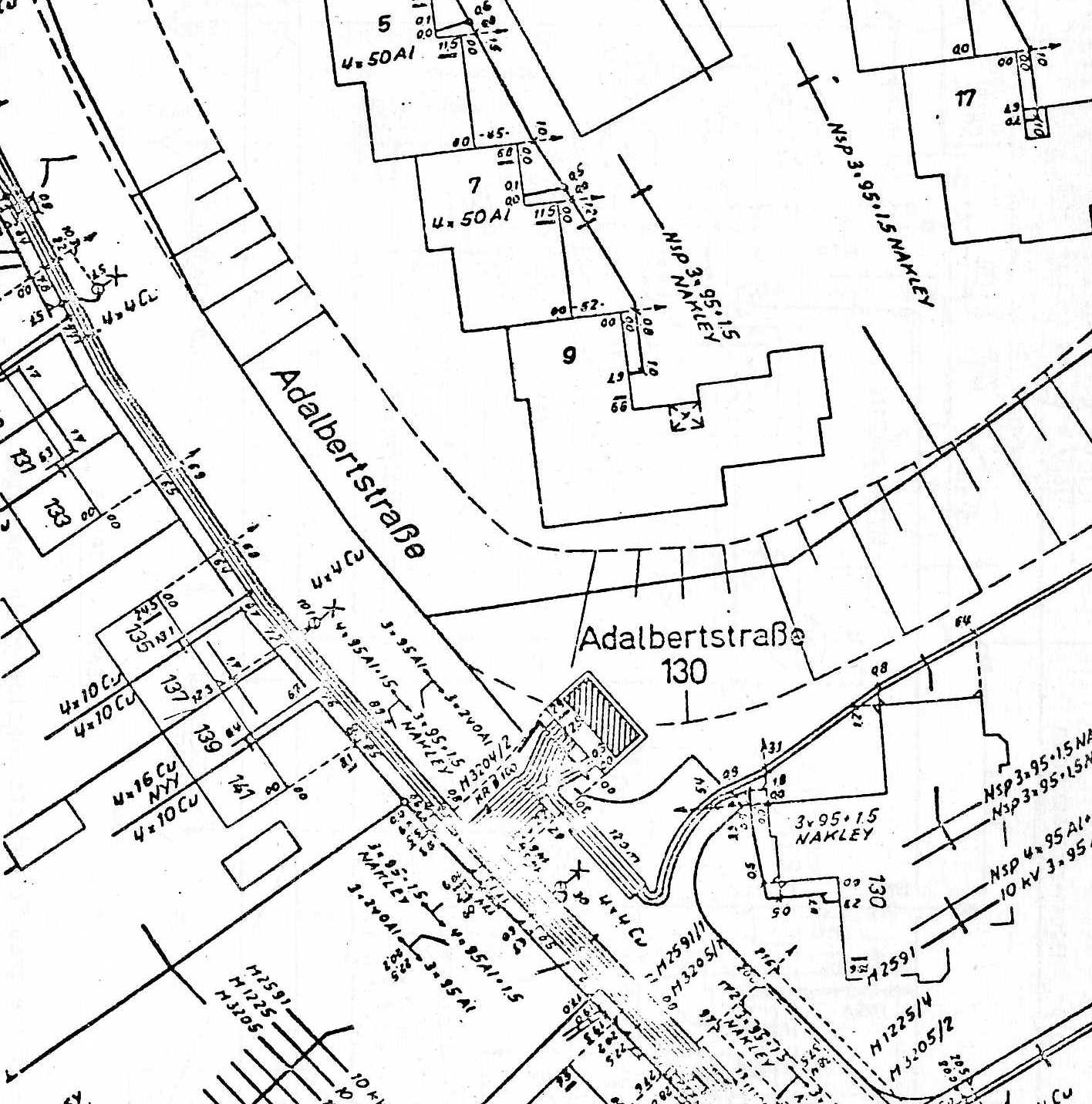
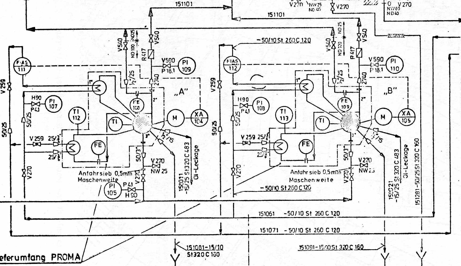
All these questions are of crucial relevance and should be discussed in great detail. Nevertheless, they will not be further discussed in this paper since it is addressed essentially to the user view of the input and to the manipulation of complex, structured graphical objects. The two pictures in Fig. 2 and Fig. 3 intend to give an idea of the picture complexity meant.
In such a view the primitives are given and defined by the user. We call them User Primitives. The content of a user primitive can for example be:
They are application dependent. Therefore the graphic system should give to the user the possibility for his definition of his primitives and must then have an automatic mapping mechanism between user primitives and system primitives [3] (Fig. 4).
The functions of a graphic system are from a user point of view:
We have then the data flow shown in Fig. 5.
The user should be able to define the syntax of his primitives and the criteria for their application-dependent plausibility (definition module). In a methods base the user may find a collection of software modules to be used for the execution of his demands. The dialog can be seen as one of the modules of the methods base and represents the interface between the user and the graphic system and also between the user and the data base. The core is a module of the methods base that can be called for the picture recording and for the picture editing. The picture editing corresponds to the picture handling e.g. to the graphical dialog. It represents the execution of graphical functions (INSERT, DELETE, CHANGE,...} on the picture buffer. The picture recording corresponds to the set up of a picture buffer through the user input under control of the user-defined plausibility criteria. The problem data handling corresponds to the manipulation and the processing of the Picture meanings to the application in hand. The control functions needed for such a system are shown in Fig. 6.
The system has to be described in a precise way. A way to do it could be the use of state and control functions. They would give together complete description of the system operation, the basic system characteristics, the system aims and serve at a later stage as information for the system specification, before a system implementation starts.
The basic state functions for the given concepts are (see Fig. 5):
The control functions are given in Fig. 6. The function f7, for example represents the call of a suitable algorithm. If s is the specification of such an algorithm and p the corresponding parameters, then we can write for f7:
f7: (s,d1,...dn) ⇒ As(d1,...dn))
The system state diagram can be built out of the state and of the control functions. If for example we have f2 (command interpretation) and f4 (command processing routine), then we can write for FDB:
FDB = f2 ο f4
(ο means concatenation of control functions). These control functions have to be mapped into the commands of the command language; the system state diagram determines the structure of the command language. Further details for this kind of specification are given in [3,4].
Every object type (user defined primitive) may be defined by a syntax block, containing the triple (structure, graphics, text).
For definition of new objects (user defined primitives) such a triple has to be defined. The three parameters (structure, graphics and text) are not independent of each other. The graphic module has the following components:
The text module has the following components:
The structure module will be discussed later. The relationship between the three modules is shown in Fig. 7.
The next question to be answered is about the user data structure, which makes the concept, as discussed so far, feasible. This data structure has to represent the mapping of the user input commands and thus to be the connection link between user on one side and data base plus graphic system (core) on the other.
The system builds this structure under control of the user-defined syntax. Since the user input does not have to be in any case structured, the first storing could be done in form of a linear set of blocks, each one containing the logic and the data of a user-primitive. Out of these blocks a structured file can be constructed using the plausibility criteria (logic). If this is not possible, then the input was incorrect and the system could output and error message.
A block in a user data structure may be a storage area for objects of the same type. The number and size of storage areas are problem dependent and have to be set up during the system definition phase. The main advantages of such a concept are
The structure of objects may be stored in a standard form like the one shown in Fig. 8.
All objects should be further structured in master and slave objects. This structuring can be easily done under the syntax control.
For the user data structure we may summarize:
The dialogue module monitors the entire man-machine communication (Fig. 9). The information coming from the physical input devices is transformed into logical input functions. This information can be
The commands control the communication between user and system (examples: load a drawing from the data base, define a menu, define a drawing area, etc.) and implement the picture editing (examples: input data, delete data, insert data). The specifications select the user-primitives to which the command should apply. These are elements of the user data structure (examples: house, street, cable, text, switchbox). The data are the parameter for the procedures (methods) activated by the system (examples: coordinates, text symbol). Attributes give additional information about the objects selected using the specifications (line type, etc.).
The syntax interpreter processes the input functions in the given context (syntax) starts and supplies (parameters) the correspondent context sensitive methods.
Based on Figs 7 and 8 we should consider two kinds of syntax controlled editors, one for graphics and one for text. The graphic editor should enable the handling of graphical data, the structure check, the updating of text position blocks and the updating of positions within the text blocks. he text editor should enable the text handling and the plausibility check.
An unsolved problem is the design of the command language for such a graphic system from a behavioural science point of view. Some design criteria have to be considered, as
For the implementation of command languages we find in existing systems mainly the model of a finite automaton. Other possibilities are fixed formats, irregular polish or the descriptive type of command languages.
The structure of the command language that could be proposed for the concepts introduced so far is based on control functions and system state diagram.
The data for graphic systems of the art discussed in this paper can be of the following type:
The existence of these four types of data and their interdependences in a single application program represents a basic difference to the classical MIS-data base systems and opens the question of their efficiency for this kind of systems. The discussion on this subject has not yet produced final results, but it seems like relational data base systems have - in this context - a larger spectrum of effective applicability.
The concepts presented and the comments made in this paper want merely to point out some ideas for an interactive graphic system as the end-user sees it and invite discussion on them. The system should be able to store, retrieve and handle a large amount of graphical, non-graphical data and logical relationships between both. It should have a transparent interface to the graphic system (core) and make arbitrary modelling procedures available to the user as modules of a methods base. Such a methods base should include context sensitive methods for use under control of a user-defined syntax.
The author would like to thank E, Alff and C. Hornung for many very valuable discussions and for reading the manuscript of this paper.
[1] Status report of the graphic standard planning committee of ACM/SIGGRAPH Computer Graphics, Vol. 11, number 3, Fall 1977
[2] Functional description of the Graphical Kernel System (GKS) (Preliminary version of the proposal of standard DIN 0066252)
[3] R. Konkart, E. Alff and C. Hornung; Graphisches Informationssystem auf der Grundlage einer relationalen Datenbank; Informatik-Fachberichte, Bd. 11, pp. 261-276; Springer Verlag, 1977
[4] E. Alff, Funktionelle Bescnreibung der Funktionsweise Graphischer Systeme unter Berucksichtigung des graphischen Dialogs; Diplomarbeit 1975; Universitat des Saarlandes, Saarbrucken.
