
In general, the user need not know how the arrays are stored in the stacks. However, the information can be quite useful to the more sophisticated user wishing to manipulate and transfer arrays from stack to stack.
Basically an array can be of one of two forms :-
The array consists of pairs of coordinates which define separate lines to be plotted. For example, an array could be X1, Y1, Z1, X1', Y1', Z1', X2, Y2, Z2, X2', Y2', Z2',...
The array consists of a set of point coordinates such as X1, Y1, Z1, X2, Y2, Z2, X3, Y3, Z3,... and this defines a set of line segments from (X1, Y1, Z1) to (X2, Y2, Z2), from (X2, Y2, Z2) to (X3, Y3, Z3) and so on.
It is also possible to have a HYBRID array which starts off in one form and changes form (possibly several times) within the array.
The picture area visible from a normal view point is 0 < X < 12, 0 < Y < 9, 0 < Z < 9. Consequently all X,Y,Z variables in the array will be of a similar size to these values. A value greater than 10000 would therefore not be a coordinate value. Five values of this order of magnitude are therefore chosen as data markers to define the type of the array information. These are as follows:-
The last two markers are used to produce hybrid arrays. Thus a stack might contain
40000, X1, Y1, Z1, X2, Y2, Z2, 30000, X3, Y3, Z3, X4, Y4, Z4, X5, Y5, Z5,
40000, X6, Y6, Z6, X7, Y7, Z7, 10000, X8, Y8, Z8, X9, Y9, Z9, X10, Y10, Z10,
20000, X11, Y11, Z11, X12, Y12, Z12, 50000
This is:-
The array 1 is a line joining   (X1,Y1,Z1)    to (X2,Y2,Z2)
The array 2 is the set of lines (X3,Y3,Z3)    to (X4,Y4,Z4)
                                (X4,Y4,Z4)    to (X5,Y5,Z5)
The array 3 is the set of lines (X6,Y6,Z6)    to (X7,Y7,Z7)
                                (X8,Y8,Z8)    to (X9,Y9,Z9)
                                (X9,Y9,Z9)    to (X10,Y10,Z10)
                                (X11,Y11,Z11) to (X12,Y12,Z12)
These are the only arrays stored in this stack.
The number of basic figures defined in the system is limited in order to keep storage requirements to a reasonable size. They fall into basically four classes. The first group consists of simple geometric shapes such as circles, triangles, rectangles, crosses. The second consists of more complex shapes which are frequently required. These include arrows and clocks. The third class is only of interest to electrical engineers. the fourth class is a set of alpha-numeric characters of variable size which can be added to a picture at any position.
All commands must be entered by means of data to the system. The column assignment is as follows:-
| Column(s) | Entry |
|---|---|
| 1 - 5 | Command Name |
| 6 | Stack Number |
| 7 - 9 | Array Number (right justified) |
| 10 | Figure Parameter |
| 11 - 20 | Argument 1 |
| 21 - 30 | Argument 2 |
| 31 - 40 | Argument 3 |
| 41 - 50 | Argument 4 |
| 51 - 60 | Argument 5 |
| 61 - 78 | Comment or Text String |
Arguments 1 to 5 can be placed anywhere within the columns allotted, provided a decimal point is included. A blank argument is read as zero. the array number must be right justified; ie the units digit of the array number must appear in column 9.
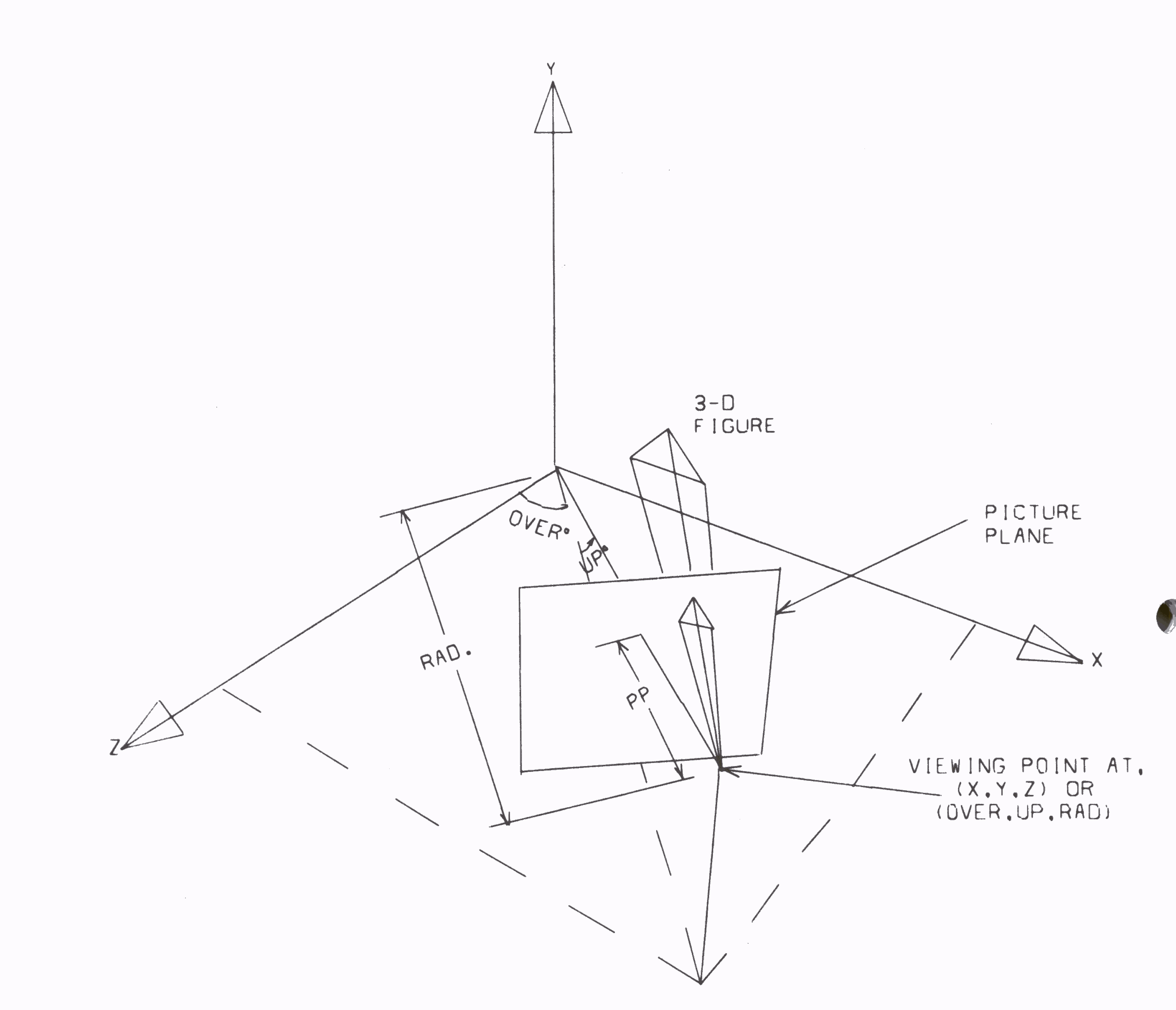
The user defines figures in an area 0 < X < 12, 0 < Y < 9, 0 < Z < 9. A viewing point of this scene is defined as the point (X,Y,Z). Alternatively, the viewing point can be defined in spherical coordinates as (OVER, UP, RAD). Both OVER and UP are given in degrees and RAD is the distance from the origin. A plane can be imagined perpendicular to the line from the viewing point to the origin. This plane is called the Picture Plane. The figure to be plotted normally lies on the opposite side of this plane. Visual rays from the figure to the viewing point pierce the picture plane, tracing out a perspective drawing as it scans the figure. It is this projected view that is calculated by the computer and plotted. The user must define the distance he requires between the viewing point and picture plane. If the picture plane is moved towards the viewer, the image becomes proportionately smaller, and vice versa. The coordinates of the viewing point can be located in any of the eight octants, so that the figure can be observed from any possible position. The following diagram illustrates the geometry.
Before drawing a frame, there is still one parameter to be fixed and that is the part of the picture plane that will be viewed. Initially the perspective point on the picture plane equivalent to the three-dimensional origin is located at the lower left hand corner of the frame drawn. It is possible to change the part of the picture plane that is viewed by defining a new position for the three-dimensional origin.
