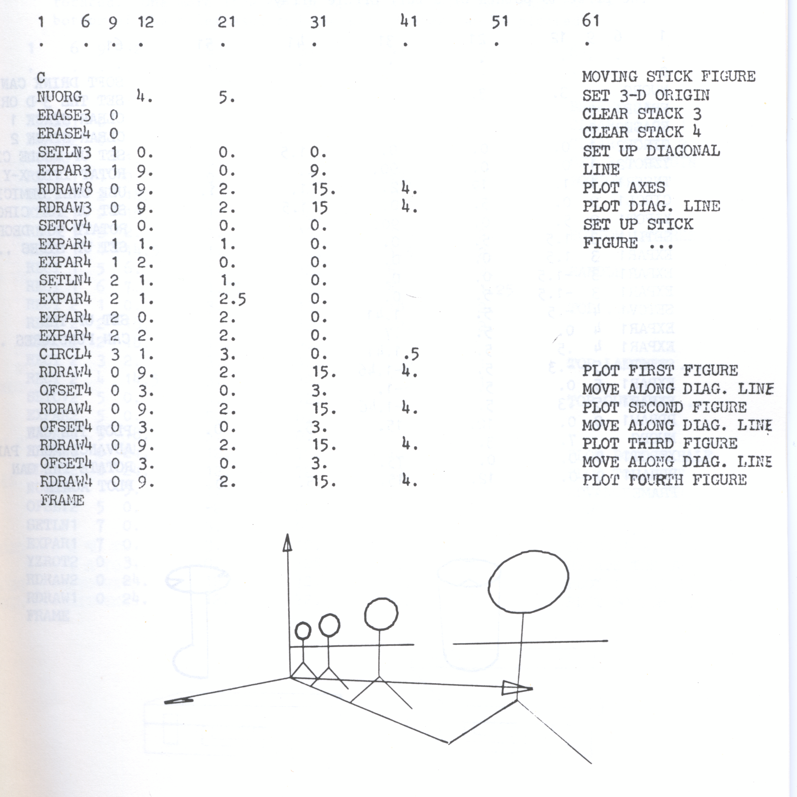
To demonstrate the effect of perspective drawings, a series of views is plotted of a stick figure advancing toward the picture plane. The standard set of axes in stack 8 is used here. A diagonal line is also shown at 45 degrees to the Z axis. The figure is advanced equal distances along the diagonal line and plotted. It appears larger as it approaches the picture plane. in the last view, it s drawn virtually the same size as the actual figure in 3D coordinates (which is 3.5 units high). This means that the picture plane is at about the same distance from the viewing point as the figure.
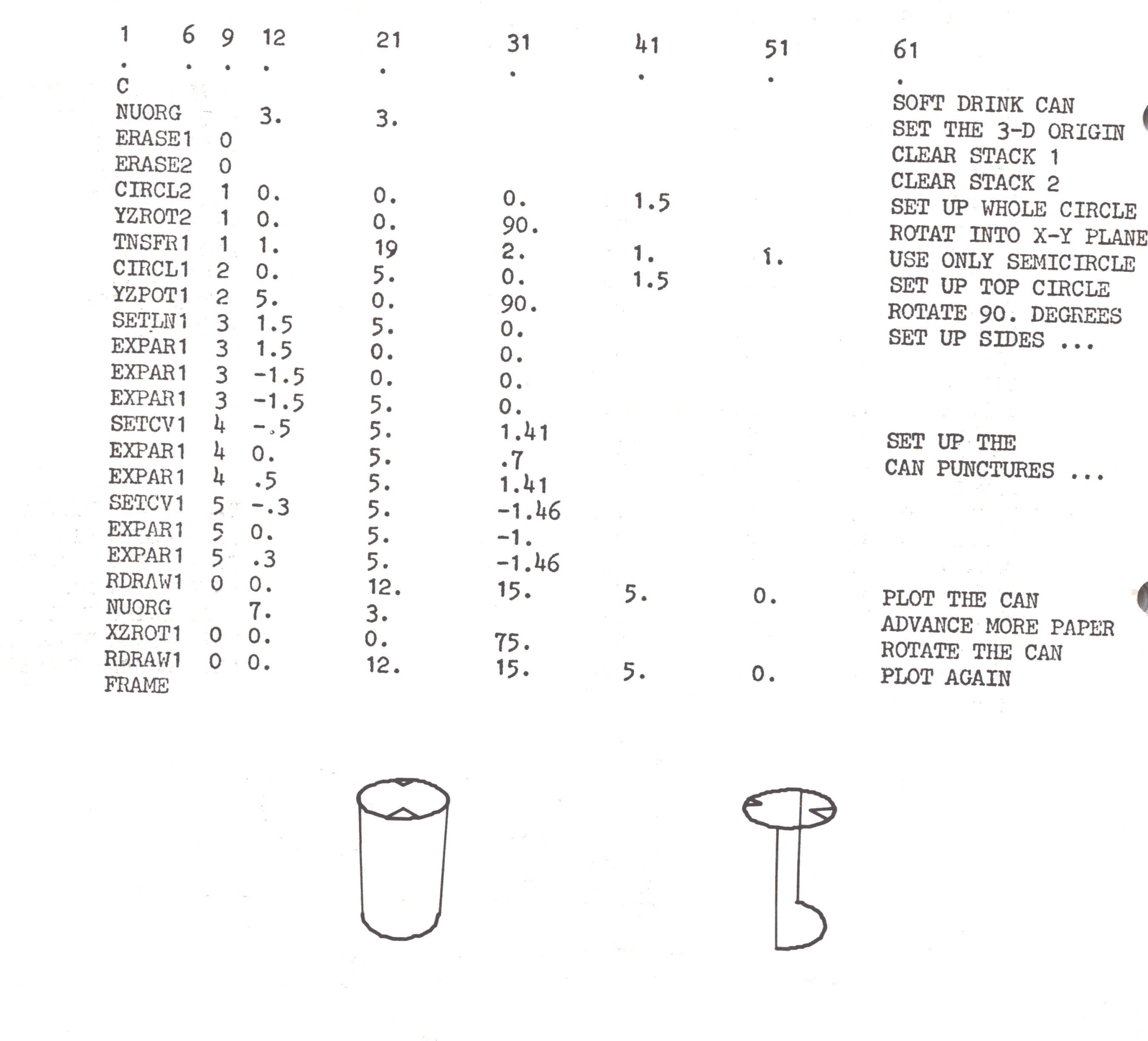
Often a round surface must be depicted in a perspective plot. This is readily handled by showing the edge as a straight line. A soft drink can, for example, can be set up by a circle, a semicircle, 2 puncture marks, and 2 straight lines for the sides. when viewed head-on, this appears quite normal. However, when either the point of view, or the can itself as below is rotated, an absurd picture results. This is because the straight lines actually represent the edge of a continuous surface. In the example below, only the can puncture (arrays 4 and 5 of stack 1) should have been rotated. Notice also that the semicircle was created by transferring the first 19 points of a full circle array.
When a moving solid figure is observed from a fixed position, certain of its edges may disappear from view. these are called hidden lines, and unfortunately it is the task of the CAMPER user to suppress them when necessary. Such a case is shown below; a brief case in fact! It is rather simply set up by a series of rectangles and plotted in the closed position. The back and left edges of the top can be seen in this first view. Before the lid can be shown rotated upwards, however, these two lines must be eliminated, and the bottom of the lid must appear. these aims are both accomplished by offsetting those two lines down two units before the lid is rotated. One more line is set up for the left-hand edge of the bottom of the brief case, and the second view can be plotted.

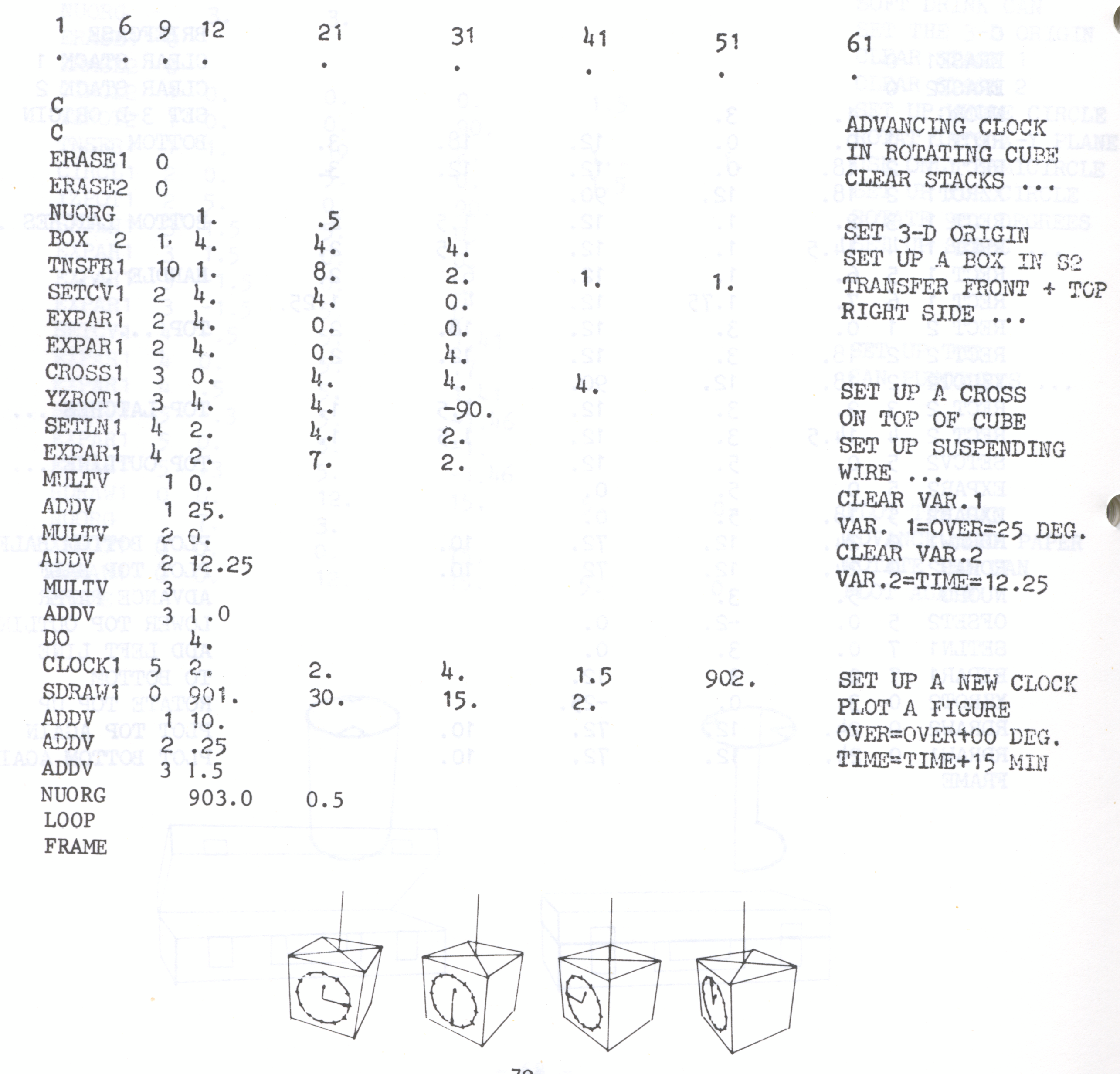
Suppose a clock is mounted on the face of a cube which rotates very slowly. to show this, a box is set up and the first eight points are transferred to plot the front and top planes only. the side plane is et up separately by a SETCV array. A cross is set up and rotated parallel to the XY plane, and a line to its centre serves as a suspending cable. Four views show the clock every 15 minutes. Variable 1 is used for the argument TIME in the CLOCK command. It is incremented by .25 each iteration; this advances the clock hands 1/4 of an hour each time. The rotation could have been achieved by rotating the whole figure, in which case the clock would have been set up parallel to the X-Y plane and rotated a little more for each view. It is slightly easier here to let the figure remain stationary, and simply rotate the point of view. this is accomplished by letting the argument OVER in the command SDRAW increase by 10 degrees for each view.