
A natural interpretation is shown to remove the apparent dualism existing between a signed number in binary form and its representation in the modulus convention. A simple circuit for signed multiplication is derived in terms of logical elements and operates unconditionally.
In conditional operations, the machine selects one of two or more courses, choosing as the outcome of discriminating on the results of earlier operations. This is certainly most fascinating, because of the analogy with the brain and some corresponding potentialities. However, by the same analogy, it is felt that discriminatory programming should be confined to the more sophisticated operations, such as those requiring iterative methods in any case; whereas simpler work, such as counting and multiplying, should be definite, i.e. unconditional. This postulate is based on analogy: nervous breakdowns are most often caused by uncertainty, i.e. unsuccessful discrimination (whether due to internal or external causes), more than by any other factor. A human who must constantly discriminate on the results of, say, his multiplications, will be likely to fail to solve a set of equations, in spite of perfect equipment in the way of theory, pen, and paper.
Inasmuch as conditional operations are based on counters, coincidence devices etc. no different from the tools of direct operations, the analogy may fail; but the conclusion drawn above still holds, as tho provision of alternative routines and discrimination processes may entail extra equipment and operating time, with corresponding increase in the probability of failure.
A number of suitable magnitude and either sign is represented by a word nA , of, say, p binary digits; in the modulus convention:
nA = A (mod 2p), for A positive.
The full implications of this convention do not seem to have been adequately realised. As applied normally, a negative number A is represented by
nA = 2p + A
This leads into difficulties in multiplication, for
A.B = nA.nB
is true only if both A and B are positive.
In some proposed techniques, the three possible sign combinations (plus a permutation) are treated conditionally; to the unsigned product nA.nB are added corrective terms 2p.(2p - nB), and 2p.(2p - nA) if nA and nB , respectively, represent negative numbers. This is done by discrimination in an extensive circuit, and involves loss of time.
This procedure is unnecessarily heavy on equipment. For the equation
A.B = nA.nB - ap 2p.nB - bp 2p.nA (1)
is true for both positive and negative numbers. The correct product A.B could accordingly be obtained on noting that ap sets up the trigger for one continuous mC (minor cycle) and bp acts on its gate for one mC, composed of the end ticks of p alternate mC's. A few additional gates, delay units, control ticks and probably an extra adder are all that is required to enable the Wilkinson multiplication circuit to deal with the negative terms of equation (1).
However, a more fundamental observation may be made on re-writing equation (1) as
    A.B = (nA - ap2p-1).(nB - bp2p-1) - ap2p-1.(nB - bp2p-1)
          - bp2p-1.(nA - ap2p-1) + ap2p-1.bp2p-1

∴
    A.B = (Σar2r-1).(Σbr2r-1) - ap2p-1).(Σbr2r-1)
            - bp2p-1.(Σar2r-1) + ap.bp22p-2          (2)
where Σ is sum over r between 1 and p-1
This corresponds to writing A as
A = -ap2p-1 + Σar2r-1 (3)
and B similarly.
Equation (3) is important because it abolishes the irksome dualism existing between a number A and the word nA representing it. For if the minus sign in equation (3) is taken as a factor -1 associated with the most significant digital place only, it is seen that the modulus convention yields the decoding relation
-ap2p-1  =  2p - ap2p-1
         = ap(2p - 2p-1) for the 2p has no meaning
∴ + ap2p-1 = -ap2p-1 in the modulus convention,
with the above proviso
In other words, if ap is 1, it represents -2p-1 .
With this result, A = nA .
It follows that the pth Δ is a sign Δ, and the advantages of a modulus representation in addition and of a sign-digit representation in multiplication are combined. This fusion is obtained without changing the modulus convention; suitable interpretation by the arithmetic organs only is needed where the convention modulus of a term differs from the original 2p .
If the two terms and their sum can have the same convention modulus, digit ap may be taken as 0 or +1 and the circuit of v.Neumann is adequate.
In accordance with the convention identity (4.), ap is taken as 0 or -1, so the two negative terms of equation (2) - say (ii) and (iii) - are dealt with instrumentally by negation (also called inversion) and addition of the fugitive digit; e.g. (ii) is
-(ap2p-1.Σbr2r-1) = (ap2p-1.Σbr2r-1) + 20 (5)
in the convention, where the ~ operation acts for the (2p)Δ of A.B. Since the ( ) of (5) contains, (p-1)Δ only, negation is naturally confined to the times of the Δ's in the ( ), so that the correction required is
20 + (Σ2q) + 2p-2 + 2p-1  =  ½(2p + 22p-1 + 22p)
where Σ is from q=0 to q=p-2
On treating the other negative terms similarly, the total correction to be applied to them is
2p + 22p-1 = (2p + 1)p + (3)p
the r.h.s. applying to the circuit of figure 2, where multiplication proper commences with ap setting up trigger L at (3)1 the P1 tick of mC (3).
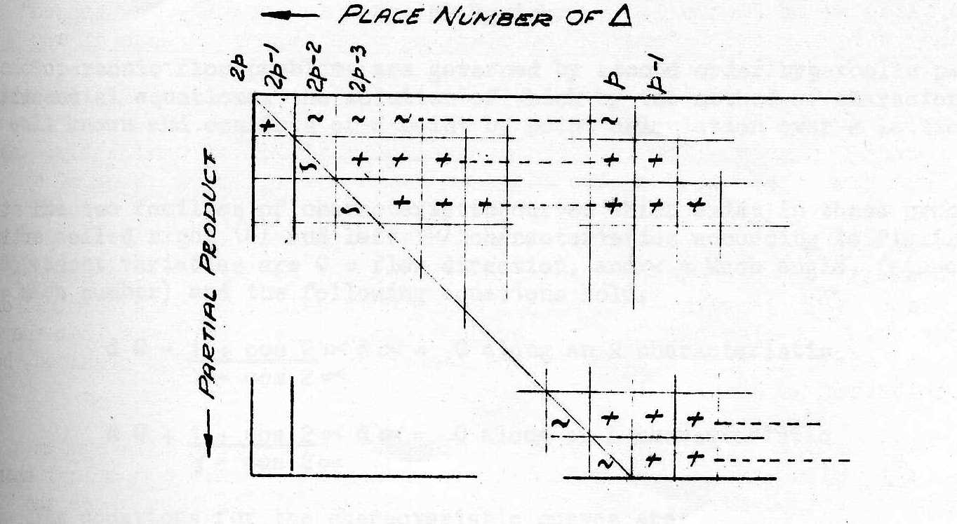
The nature of the partial products is illustrated by the rows of figure 1. The first row arises from ap: its Δ are negated excepting that of weight 22p-2; the latter is apbp22p-2, term (iv) of equation (2), the. rest for term (ii). The remaining partial products are each composed of (p-l) positive Δ's, representing term (i), and have the pth Δ negated to yield term (iii).
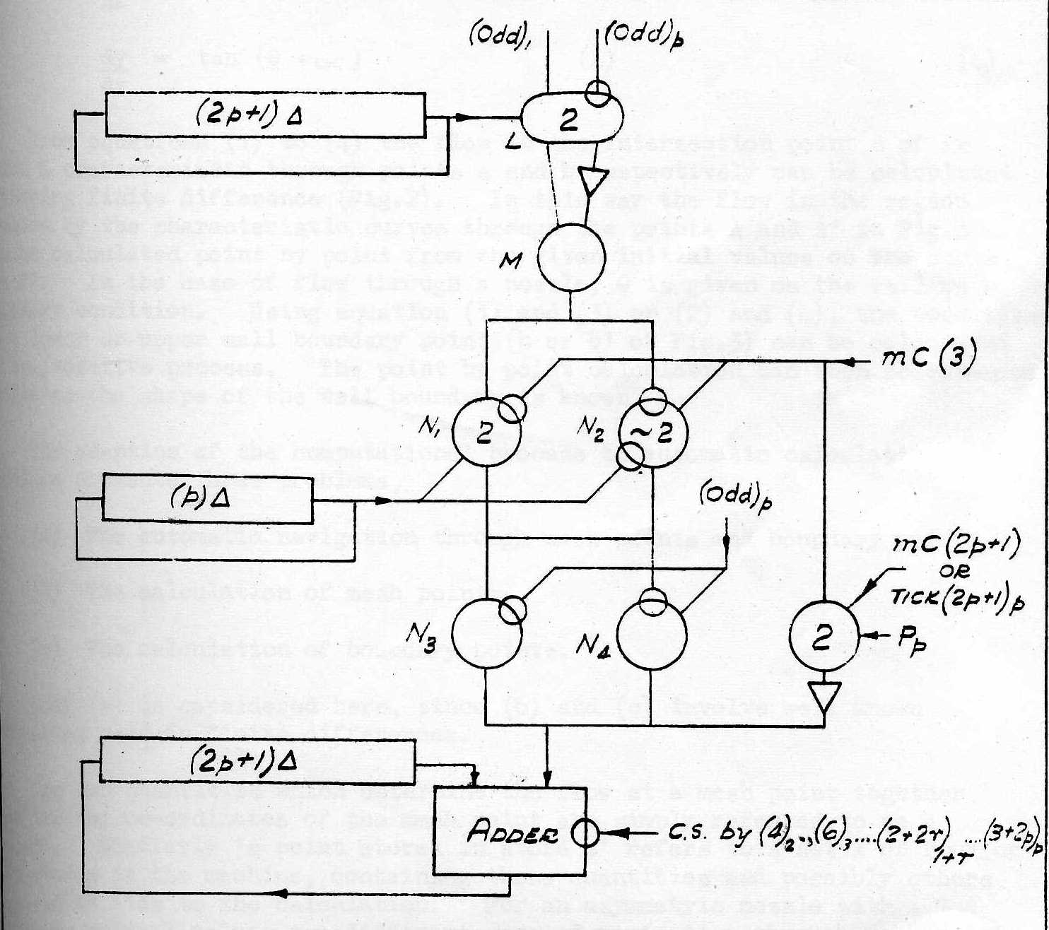
The corresponding circuit (figure 2) is an elaboration on Wilkinson's. The usual N element is N1 and its output joins that of N2. This is a (~2) element which yields zero output unless its input is stimulated, when its output becomes ~(A.B), where A.B are fed to the two inhibitor connections of the (~2). (A (~2) would be realised most economically by a (1) with (2) inhibitor-terminals of joint inhibition threshold 2). The output of N1, and N2 is fed to the input of N3 and the inhibition connection of N4. N3 and N4 are (1) elements with joined outputs. N3 is inhibited and N4 stimulated by (odd)p, i.e. by the end ticks of the alternate mC's when trigger L is set up by ar, r = 1 - p.
The circuit has the effect of feeding to the adder ar Σbq (for q=1 to p-1) via N1 and N3, followed, by ~ (ar.bp) via N1 and N4 for r = 1 to p-l. When r = p, N1 is inhibited and N2 stimulated, so that ~(apΣbq), (q=1 to p-1) and ~~(apbp) = +(apbp) is passed out. This is as required, the "weights" (omitted here) being correct.
The correction ticks were discussed above. They can be inserted when the N-strearn is zero, delayed 1Δ from the ends of mC (3) - when ap is set up - and of mC(2p+l) - when a1 is set up. This requires a (2) fed with Pp, (3), (2p+l), and also a single delay unit. Since a slow counter is required to time serial multiplication in any case, the special mGC's or tick required will be readily obtained.
Hence the extra equipment required to make a multiplying circuit sensitive to sign is of the order of an adder circuit, i.e. four elements and a single delay unit.
In unsigned multiplication, no C.S. is required since the product of two (p) Δ words, each < 2p, is a (2p)Δ word < 22p. The latter part of this statement holds a fortiori in signed multiplication, but the addition of correction ticks 22p+1 and 2p means that the product may exceed 22p, i.e. the product <22p+1 only. Hence the multiplier can produce a (2p+l)th digit 22p. This may be dealt with in various ways: i.e. by
In the last method, it might be thought that isolated C.S. pulses could be used, e. g. at the 22p-1 tick following the formation of the first partial product. A simple example shows that this is not feasible: if A = -2p-1 = B.
ar = br = 0 for r ≠ p,
ap = bp = 1
then first partial product
= ap2p-1.bp2p-1 + ap2p-1.Σbr2r-1 for r = 1 to p-1
= 22p-2 + 2 p-1(2p-1 -1) = 22p-1 - 2p-1
and since
-2p-1.-2p-1 = 22p-2, it is clear that the Σ2r-1 for p = p to 2p-2 of the first partial product must be cleared by C.S., after addition of later partial products.
Since the advancing C.S. pulse may be available from a slow counter and as this method allows the product tank to serve as an accumulator, it is indicated in figure 2.
The time consumed is the same as in unsigned multiplication, i.e. p.(2p+l)Δ, not including time for the instruction to take effect.
The procedure is readily applicable to systems of multiplication wherein multiplier and product tanks are of integral word length, i.e. where a slow clock or an in-out unit delay operate on the multiplicand.
Since the reading of the paper, D.W. Davis has examined figure 2 with a view to applying circuit techniques and, (during an interval of the conference) has suggested a logical equivalent; the (~2) element N1 and the inhibitor connection of the (2) element N1 are eliminated, a (≢) element fed with mC(3) and (odd)p being provided for control of the (1) elements N3 and N4. This arrangement has the incidental advantage of easy change-over from signed to unsigned multiplication, the output of the (≢) element being all that is involved, apart from the two correction ticks.
The procedure here described may be of interest also in simplifying the relevant programme routine of a computer which does not feature an independent multiplication organ.
Finally, it may be remarked that the construction of small, special purpose as distinct from large, universal computers is made more attractive by the possibility of having a circuit for signed multiplication on the simple lines here described.
Example 1. To illustrate equation (3), taking 2p = 16, A = -5. In the convention, the negative integers -1, -2, .., -8, appear as 15 (mod-16), 14 (mod 16), .... 8 (mod 16), respectively. Thus, to code A, the decimal number -5 = (l6-5) (mod 16) = 11 (mod 16) is put in binary form nA.= 1011 (the most significant digit being to the left). By the proviso given in the test, this is interpreted as
nA = -1000 + 0011, i.e. -8+3 = -5 decimally,
i.e. nA = A.
Similarly, the positive number, B = 5 has coded binary representation nB = 0101, which is interpreted as
-0000 + 0101 = -0 + 5 = +5, i.e. nB = B.
This amounts to interpreting the conventionally coded binary word as the positive number apparently represented and deducting twice the number represented by its sign digit only. The truth of this is self-evident, providing only that the numbers involved are small enough, i.e.
-2p-1 ≤ A < (2p-1-1) must hold.
Example 2. For signed multiplication, one proceeds in the same manner as for unsigned multiplication, but as indicated by figure 1:
any digit in the partial product containing the sign digit of one factor only (but not of both) is inverted, i.e. 0 is written as 1, and v.v.; also, to the sum of the partial products is added (22p-1+2p).
To calculate (+2) × (-4), i.e. 010 × 100, both (mod 23)
                          Place No. of Δ
                          6 5 4 3 2 1
first part.  prod.          0 1 1
second part.  prod.           0 0 0
third part.  prod.              1 0 0
                          ------------
sum of part,  prods.      0 1 0 0 0 0
22p-1                     1 0 0 0 0 0
2p                        0 0 1 0 0 0
                          -----------
Answer                    1 1 1 0 0 0 (mod 26) = -32+16+8 = -8
Example 3. To calculate 0 × 0, i.e. 000 × 000 (both mod 23)
                          6 5 4 3 2 1
                            0 1 1
                              1 0 0
                                1 0 0
                          -----------
                          0 1 1 0 0 0
                          1 0 1 0 0 0  22p-1+2p
                          -----------
             answer 1)    0 0 0 0 0 0  (mod 26) = 0.
There is another unconditional method of signed multiplication; the digits of the partial products to be subtracted (as shown by equation (3.) and the tilde ~ in figure l) in forming the complete product are topped where they were negated before; i.e. starting with the occurrence of any such digit in a partial product, it is added into every place further to the left, ending with the (2p)th. No fixed correction ticks are then required.
The unsigned multiplication circuit need be modified only slightly; to the lead from the gate N to the adder is added a loop, consisting of a unit delay" and a (2) stimulated so that the preceding N output repeats at times (2r + 2)1-r r = 1 to p; this deals completely with all the partial products except the highest. The latter is treated by returning the adder output via a (2) (activated in mC(3)) and a unit delay, to that terminal of the adder which is also fed from the product tank. It so happens that the term +apbp22p-2 is topped twice by the mechanism; this is not required, but may be tolerated as adder C.S. nullifies it.
It will be seen that the only extra elements required in this system are two (2) elements and two unit delays, rendering it more economical than the system discussed first. The advantage, however, disappears where the system is such that the product tank is not empty when the highest partial product is formed, as the topping method then requires an extra adder.
