
Supersonic flow problems are governed by second order hyperbolic partial differential equations, the solution of which by the method of characteristics is well known and consists of a point by point calculation over a lattice mesh.
The two families of characteristic curves which exist in these problems may be called right (R) and left (L) characteristics according to Fig.1.
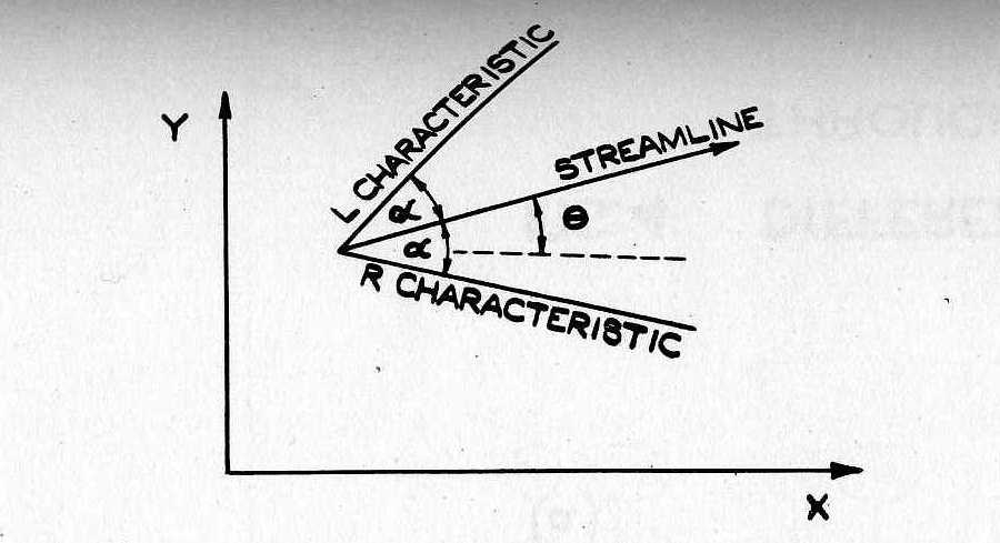
The independent variables are θ = flow direction, and α = Mach angle, (sin α = 1/M; M = Mach number) and the following equations hold:
d θ - (1 + cos 2α)/(γ - cos 2α)  dα = 0 along an R characteristic     (1)
d θ + (1 + cos 2α)/(γ - cos 2α)  dα = 0 along an L characteristic     (2)
The equations for the characteristic curves are:
dy/dx = tan(θ - α)        (R)                      (3)
dy/dx = tan(θ + α)        (L)                      (4)
dy 5= tan dx
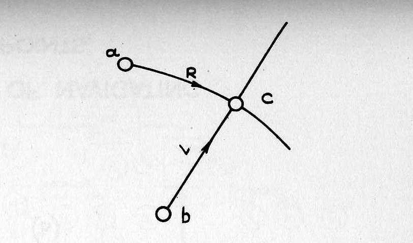
From equations (1) to (4) the flow at the intersection point c of an R and L characteristic through points a and b respectively can be calculated employing finite difference (Fig. 2).
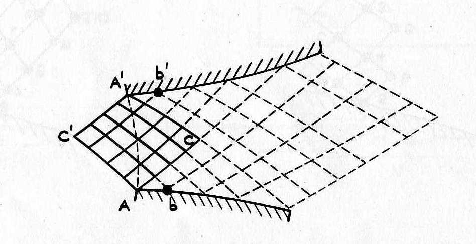
In this way the flow in the region bounded by the characteristic curves through the points A and A' in Fig.3 can be calculated point by point from the given initial values on the curve A - A'. In the case of flow through a nozzle, θ is given on the wall as a boundary condition. Using equation (1) and (3) or (2) and (4), the conditions at a lower or upper wall boundary point (b or b' of Fig.3) can be calculated by an iterative process. The point by point calculation can then be extended as far as the shape of the wall boundary is known.
The adaption of the computational process to automatic calculating machines presents three problems,
Only (a) is considered here, since (b) and (c) involve well known procedures used in finite differences.
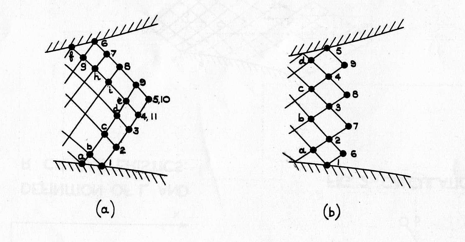
The two quantities which determine the flow at a mesh point together with the two co-ordinates of the mesh point are simply referred to as a point. Similarly a point stored in store s refers to a set s of four or more stores in the machine, containing these quantities and possibly others required as aids to the calculation. For an asymmetric nozzle with arbitrary initial values two different ways of navigation through mesh points are shown in Fig.4a and 4b. We shall, for brevity, denote by a step the process of calculating the points denoted by numbers, in the order given below from the points denoted by letters which were calculated in the previous step.
Starting with the given initial points, the calculation of the whole flow fields proceeds by repeated steps until either a preassigned position or a specified maximum Mach number is reached on the wall boundary.
The number of points (n) chosen initially remains the same for all steps and is determined by considerations of accuracy and the storage capacity of the machine. The choice of the curve on which the initial mesh points lie determines the pattern of the mesh points obtained in subsequent steps, the choice between the alternative ways of navigation depends upon the form that the final result is required to take at the nozzle end.
The two main blocks of calculations during a step are the calculation of two wall-boundary points (upper and lower wall) and the calculation of a mesh point which is repeated n - 2 times. As an example the case of Fig,4a is considered in detail for n = 9 points.
The store contents at the beginning of a step with reference to Fig.4a may be exhibited thus:
Store No:        P1  P2  P3  P4  P5  P6  P7  P8  P9  P10
Contains Point:  a   b   c   d   e   f   g   h   i   e
Tabulated quantities for the lower wall boundary are contained in stores Q1 to Qm; for the upper wall boundary in stores R1 to Rm.
The procedure then is to calculate:-
Boundary point No.1 using contents of Stores P2 and Q1-Qm; result to store P1
Boundary point No.6 using contents of Stores P7 and R1-Rm; result to store P6
Mesh point No.2 using contents of store P3 and P1; result to store P2
Mesh point No.3 using contents of store P4 and P2; result to store P3
Mesh point No.4 using contents of store P5 and P3; result to store P4
Mesh point No.7 using contents of store P6 and P8; result to store P7
Mesh point No.8 using contents of store P7 and P9; result to store P8
Mesh point No.9 using contents of store P8 and P10; result to store P9
Mesh point No.10 using contents of store P9 and P11; result to store P10
The flow diagram for this calculation is shown in Fig.5. Block A contains orders for the calculation of the lower wall boundary point No.1 using the contents of store P2 and the information on the lower wall boundary ; given in stores Q and placing the result into store P1. The upper wall boundary point No.2 then follows in block B. In block C mesh points are calculated.
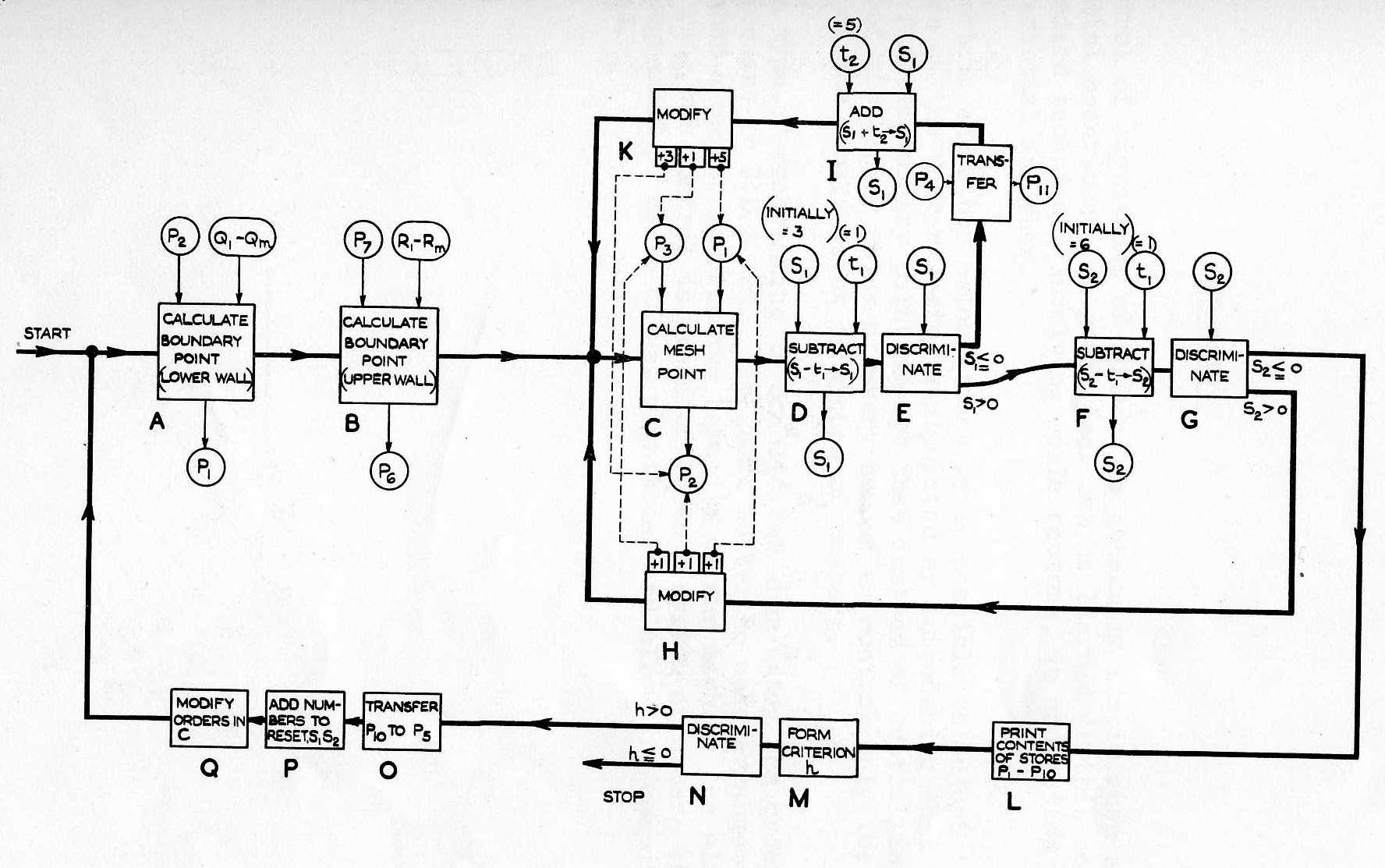
First the mesh point No.2 is calculated using stores P3, P1, and placing the result in store P2; followed by passage through blocks D, E and F, G which are used as counters. The modification orders in Block H. then prepare the orders in block C for the calculation of mesh point No.3 by adding the numbers +1; +1; +1 to the appropriate stores specification numbers. This cycle is repeated until mesh point No.4 is calculated. The counter D, E, after being passed J times, then causes a changeover to the orders in blocks I. In these blocks the contents of store P4 are transferred to store P11 and the number 5 contained in store t2 is added to the store S1 required for the discrimination in block E. The orders in block C are then prepared for the calculation of mesh point No.7 by the modification orders in block K which add +3; +1; +5 to the specification numbers of the appropriate stores.
Because the number in store S1 used for discrimination in Block E is positive again, the counter D, E causes a change over to the counter F, G and therefore the cycle represented by blocks C to H is repeated, calculating mesh points No.7 - 10. The calculation of mesh point No. 10 completes one step. Counter F, G which then is passed for the sixth time leads on to the orders in block L which then print the result of the calculation of one step. In the following block M a criterion h is formed indicating whether a further repetition of a step is required by subtracting from a prefixed quantity (for example, X-coordinate or flow velocity) the corresponding quantity obtained as a result of the calculation. The discrimination operation in block N, then either initiates a repetition or stops the machine. If the calculation of a step is to be repeated the orders in blocks O, P, Q reset the machine to its original condition. Orders in block O transfer the contents of store P10 to P5; orders in block P obtain, by addition, the initial numbers required in stores S1 and S2 for counting, and the modification orders in block Q change the store specification numbers in block C to their initial values.
For the case of Fig.4.b the same flow diagram is used but different modification orders are required.
Here the store contents at the beginning of a step are:-
Store No.:	        P6   P7   P8   P9
Contains point No.	a    b    c    d
Wall boundary points are as in the previous case. Stores S1; S2; t2 contain initially the numbers 3; 6; 5.
The procedure then is to calculate:-
Boundary point No.1 using contents of stores P6 and Q1-Qm; result to store P1
Boundary point No.5 using contents of stores P9 and R1-Rm; result to store P5
Mesh point No.2. using contents of store P6 and P7; result to store P2
Mesh point No.3. using contents of store P7 and P8; result to store P3
Mesh point No.4. using contents of store P8 and P9; result to store P4
Mesh point No.6. using contents of store P1 and P2; result to store P6
Mesh point No.7. using contents of store P2 and P3; result to store P7
Mesh point No.8. using contents of store P3 and P4; result to store P8
Mesh point No.9. using contents of store P4 and P5; result to store P9
The calculation of the boundary points differs from the previous case in the store numbers required in A and B. The cycle represented by blocks C to H is now carried out three times, with the modifying orders in block H, adding each time +1; +1; +1 to the store specification numbers of block C. Thus mesh points No.2 - 4 are calculated. The counter D, E then causes a change over to the orders in blocks I and K. In blocks I the transfer operation is not required; only the counter D, E is reset by adding the number 5 to store S1 as in the previous case, and in Block K the numbers +2; -7; -7 are added to the appropriate store numbers in block C. The cycle represented by block C to H is then carried out four times, thus calculating mesh points No,6 to 9. Counter F, G after being passed the sixth time then changes over to the orders in block L. The rest of the procedure is similar to the previous case.
More complicated supersonic problems, such as flow round axially symmetric bodies at zero incidence, which includes a shock wave, can be programmed in a similar manner. Problems which cannot be dealt with in the way shown here are those where an interaction of characteristic curves of the same family occurs, that is where a weak shock is formed within the flow region considered.
