The Ferranti Atlas computer is one of the two or three most powerful machines in the world today. It marks the culmination of a long and fruitful collaboration between Ferranti Ltd and the Department of Electrical Engineering at Manchester University. This joint effort began with the construction of the Ferranti Mark I computer, which was the first stored program digital computer ever built for sale by a manufacturer. The collaboration has continued with the development of the well-known Ferranti Mercury computer, installed at Harwell, CERN, London University and sixteen other locations.
Atlas has a minimum main store of 114,688 48-bit words of which at least 16,384 words are in cores and the balance is in drums. These stores are integrated by special hardware so as to appear as a single level store to the user. What appears to the user as a continuous strip of storage is physically represented by a series of 512-word blocks distributed throughout the core and drum stores. The allocation of this storage is carried out entirely automatically.
Atlas has 128 index registers, double modification and a floating point accumulator. Overall speeds are of the order of 700,000 instructions per second. A unique feature of Atlas is the fixed store, which provides exceedingly rapid access to a set of permanent routines which are thus built into the machine. The allocation of storage mentioned above is carried out by routines in this fixed store which ensure continuous optimisation of store use. Similarly, fixed store routines control input and output operations and provide extensions to the basic function code of the machine.
The Atlas system operates on a thoroughgoing multi-programming basis. Programs written entirely independently share time on the central computer. This is possible because full hardware protection against mutual interference of programs is a direct consequence of the method of automatic storage allocation used.
The tasks to be carried out by Atlas are scheduled entirely automatically by a supervisor routine of advanced conception. Jobs to be run on the computer are first assembled on magnetic tape by the supervisor, they are then executed along with a few other appropriate companion jobs with which they share the central computer and the results are distributed via magnetic tape to appropriate output peripherals.
In general, around 200 jobs may be in the system at any one time of which perhaps a dozen may be in the execution phase. The management of the whole work load so as to ensure optimum use of the central computer and its peripherals is carried out entirely automatically by the supervisor.
The Atlas system thus provides very large quantities of computing at an extremely low cost per operation, with access to extremely large areas of storage backed by very fast tape. These facilities are essential to all those users who need an economic means of achieving a major breakthrough in computing power in order to advance their work to the next stage. Such users include all the leading groups in the fields of crystallography, meteorology, supersonic aviation, nuclear engineering and space research. In addition to these well-established consumers of ever-growing quantities of computing there are innumerable other scientific and technical projects whose progress can be accelerated by cheap access to relatively small amounts of computer time. The Atlas computer with its automatic supervisory system enables the needs of all these users, both great and small, to be met. Atlas provides the ideal nucleus for a multiple user computing facility, providing better service at lower cost than is obtainable in any other way. That is why Harwell and London University have ordered Atlas. It is a choice to be considered carefully by every large user.
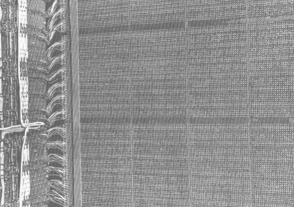
Atlas has a series of stores at different levels of access time. The fastest of these is the fixed store of 8,192 words which has an access time of 0.3µs. Once the contents of this store have been determined and set they cannot be changed by an operation of the machine but only by physically altering the hardware. The store itself is constructed from a woven wire mesh into which are inserted ferrite rods to represent ones and copper rods to represent zeros as shown in Figure 1. It contains certain routines - known as extracodes - for common mathematical functions such as polynomial evaluation and trigonometric functions. An extracode routine can be called in by the programmer as a single instruction and he need have no knowledge whatsoever of its interpretation within the fixed store. The extracode takes up about 2,000 of the available 8,192 words, the remainder being allocated to the supervisor program.
The fixed store has associated with it a subsidiary store of 1,024 words which it uses as working space. This store has a 2µs cycle time and is locked out from all ordinary program commands. It is thus private to the fixed store routines.
After the fixed store the next in speed is the B-store. This contains 128 half-word (24-bit) index registers to which access can be made in 0.35µs. Associated with the B-store is the B-arithmetic unit used for operations on indices; this unit is quite distinct from the floating-point accumulator and floating-point arithmetic may take place at the same time as indexing arithmetic.
The main store of Atlas has a cycle time of 2µs. This time is, however, effectively reduced by the provision of a number of distinct access systems to sections of the store. The core store of a basic machine is 16,384 words. The core store is backed up by drums containing 24,576 words per drum. A basic installation will normally have 4 drums. Both levels of storage may be increased up to a theoretical maximum of 1,048,576 locations of core and drum store combined. A drum cabinet contains 4 drums and additional drums will usually be added in multiples of 4. A drum co-ordinator organises transfers of information between core and drum stores and can be attached to a maximum of 16 drums. Further co-ordinators are required if more than 16 drums are attached. Words are written on the drums in multiples of 512 words, and transfers between drums and core store are by these blocks; 512 words is also the block length on the magnetic tape. A drum revolves at 5,000 rpm giving a revolution time of 12ms and a time to transfer one block of 2ms plus any waiting time necessary.
Finally, there is a set of registers which are referred to collectively as the V-store. These consist mainly of information and control signals connected with magnetic tape, drums and other peripheral equipments. They are not allocated in the same area geographically but in different parts of the machine. The page-address registers which the one-level store concept depends on are part of the V-store. The organisation of the storage system as a whole is shown in Figure 2.
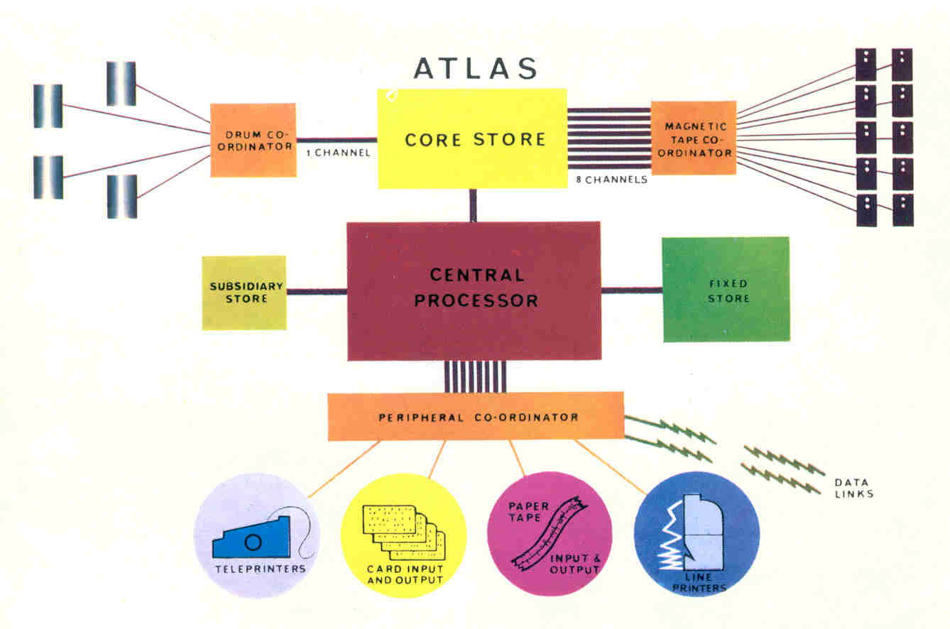
The speed of Atlas makes it possible to simplify the method of attaching peripheral devices. Transfers to and from all devices except Ampex magnetic tape and drums are handled by a single peripheral coordinator. Whereas in other large machines comparatively large sections of information are transferred by special control units, in Atlas transfers are carried out under the control of fixed store programs via small buffers in units of information of character size. For example, this unit will be one 5 or 7-hole character for paper tape equipment, one column of an 80-column card for a card reader and 16 6-bit characters for IBM magnetic tape.
The small amounts of electronics associated with each peripheral device are housed in a peripheral coordinator, two types A and B of which are offered. The maximum number of devices which can be attached to these coordinators are:
| Peripheral | Type A | Type B |
|---|---|---|
| TR5 reader | 4 | 8 |
| TR7 reader | 1 | 4 |
| Teletype 110 punch | 4 | 8 |
| Creed 3000 punch | 1 | 4 |
| Creed 75 teleprinter | 3 | 4 |
| Anelex printer | 2 | 4 |
| Card reader | 2 | 4 |
| Card punch | 1 | 2 |
| Graphical output | 1 | 1 |
| IBM Tape Channel | 1 | 1 |
| General Channel, 24-bits in/out | 6 | 6 |
| General Channel, 12-bits in/out | 12 | 12 |
| General Channel, 4-bits in, 12-bits out | 12 | 12 |
An instruction counter and clock are also included.
In the case of the Ampex Tape and Drums, two special co-ordinators are provided, called the Tape Co-ordinator and the Drum Co-ordinator.
Input and output is normally via 7-channel paper tape but 5-hole tape may also be used. The readers which can be attached are the Ferranti TR5 and TR7 readers operating at maximum speeds of 300 and 1,000 ch/sec respectively.
Output can be either by the Teletype 110 ch/sec or by the Creed 3000 punch with a maximum speed of 300 ch/sec.
The standard card reader on Atlas is the ICT 593, which has a maximum speed of 600 cards/minute.
The ICT 582 punch operates at 100 cards/minute.
Both these devices operate on 80-column punched cards.
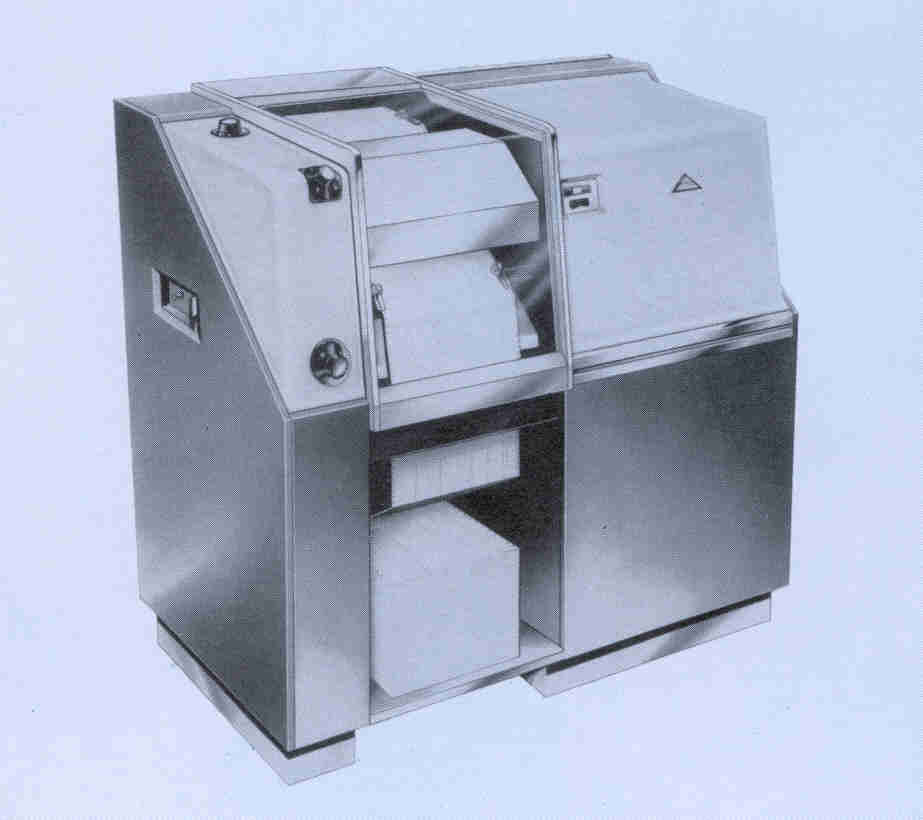
The Anelex 4/1000 printer has been adopted as standard on Atlas. It has a maximum printing speed of 1,000 lines/minute under the most favourable program conditions and a minimum speed of 815 lines/minute. There are 120 printing positions on a line. This printer is illustrated in Figure 3.
IBM ½in magnetic tape can be attached to Atlas via the peripheral coordinator. Up to three 729 MK IV decks can be attached but only one may be in operation at any one time. A 96-bit buffer is provided in the coordinator enabling the IBM tape to run at its maximum speed of 62,5000 ch/sec.
The format of the tape is standard IBM, i.e. variable length records with lateral and longitudinal parity.
A graphical output device consisting of a 4,096 × 4,096 array can be attached to each type of peripheral coordinator.
Other devices can be attached such as MPL magnetic tape which is connected to Atlas through one paper tape input channel and one paper tape output channel. This tape is ½in and has a packing density of 100bits/in. It can be run at four different speeds, the maximum being 10in/sec.
The general channels on the peripheral coordinator can be used for other suitable devices.
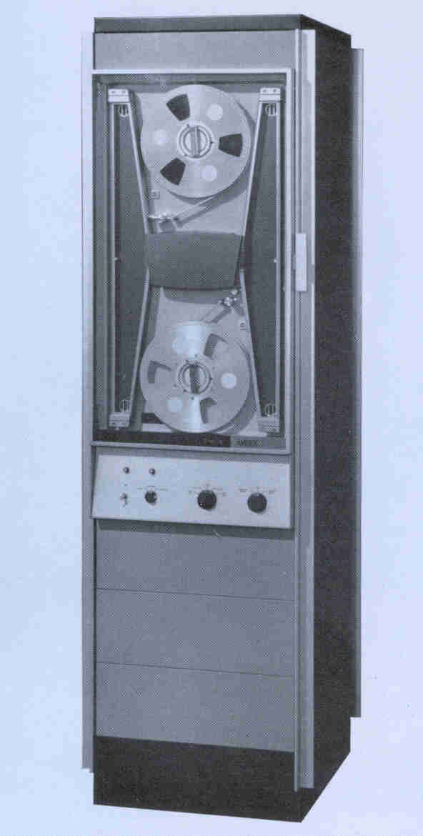
The main magnetic tape mechanism on Atlas is the Ampex TM2 system as shown in Figure 4, operating with 1in tape. Each machine has 8 channels through which simultaneous tape transfers can take place, and an installation can have a maximum of 32 decks. A switching unit controls 8 decks on two channels thus enabling two of each group of 8 decks to be operating at one time. The tape can be read while it is travelling either forward or backwards but writing can only take place in the forward direction.
The tape is divided into 512 48-bit word blocks enabling about 5,000 blocks, i.e. 20 million characters to be held on one 3,600 ft tape. There are 16 tracks across the tape of which 12 are for information. A 48-bit word is therefore represented by four 12-bit stripes across the tape. At the end of each block is recorded a 24-bit checksum and each block is preceded by a block marker and block address and is terminated by a trailing block marker and what is effectively a zero block address. The speed of the tape is 120in/sec which implies an instantaneous transfer rate of 90,000 ch/sec. The effective transfer rate, i.e. the rate allowing for the gap between each 512-word block, is 64,000 ch/sec. This also means that if purely numeric data are present on the tape the instantaneous transfer rate is equivalent to 120,000 decimal digits/second.
All tapes are pre-addressed by a special run on the machine thus making it possible to omit faulty blocks on a tape before it is used. All the tape transfers together with wind and rewind procedures are under the control of fixed store routines. These routines are designed to diagnose as far as it is possible any errors occurring during operation. For example, when a block of information is being read from tape a checksum is formed and if this fails to agree with the checksum on the tape, the block is re-read. In all three attempts are made to read the block. If this is unsuccessful a further attempt is made to read the suspect block but this time with reduced bias level. The mechanism will be disengaged and the program suspended if this again fails. If it is successful however, the tape is copied to a free tape and the operator is instructed to re-address the faulty tape. If the first block has not been read successfully it is most likely that the mechanism itself is faulty and the operator is instructed to remount the tape on another deck.
At all times during this and any other fault procedure, the engineers are informed of all errors.
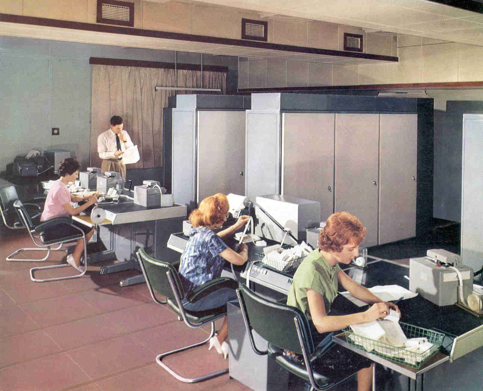
There are three types of console in an Atlas installation - main, slave and engineer's. A standard installation will have one main, two slave and one engineer's console but additional slave consoles can be attached if necessary.
On the main console there will be on-line a TR5 tape-reader, teletype 110 tape punch and a Creed 75 teleprinter and off-line a Flexowriter for tape-editing purposes. The teleprinter will normally be used by the supervisor for informing the operator of the state of the machine and giving him any instructions or monitoring information.
Slave consoles will be similar to main consoles but with no teleprinter.
The engineer's console has a TR5 tape-reader, Creed 75 teleprinter, the display lights which form B-line 120 and the engineer's switches and controls. It will normally be reserved for maintenance while the principal operator will use the main console and from there will be able to give instructions to the supervisor. Slave consoles are purely input/output stations.
There is also a Creed 75 teleprinter for giving information and instructions to the magnetic tape operators.
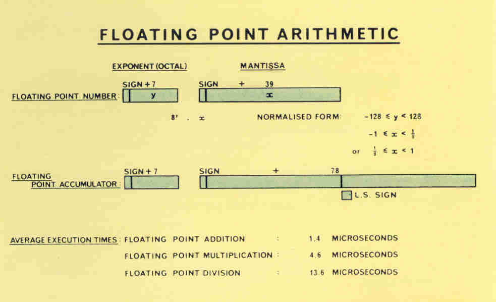
The Atlas word length, excepting the B-store, is 48 bits, each 24-bit half-word having a parity bit associated with it. The word can be thought of for example as a single-address machine instruction, 8 characters of 6 bits each or as a single floating point number, as shown in Figure 5.
[Amendment No 1: The following average instruction times for floating point operations
were obtained on the Manchester University Atlas on 7th December, 1962. They should
be considered to supersede the times in this document.
Addition, unmodified: 1.61 microseconds
Addition, singly modified: 1.94 microseconds
Addition, doubly modified: 2.61 microseconds
Multiplication, all cases: 4.97 microseconds
Division, all cases minimum: 10.66 microseconds
Division, all cases maximum: 29.80 microseconds ]
In the Atlas representation of a floating point number 8 bits are used to represent the exponent y and 40 bits the mantissa and sign x. The exponent is an octal one and the number represented is therefore x 8y . Twos complements are used for negative numbers, so that when normalised, ⅛ ≤ x < 1 or -1 ≤ x < -⅛ and -128 ≤ y < 128. Floating point arithmetic makes use of a floating point accumulator, in which the mantissa is double length (sign and 78 bits).
There are many far-flung organisations in which satellite computers, data links or remote control desks would be necessary to utilise a large central computer adequately. Ferranti Ltd are at present developing such equipment and will be pleased to put forward proposals for any such system.
There are several distinct phases in the obeying of an Atlas instruction. These are generally as follows:
The overlapping of instructions means that when an instruction is being obeyed another one may be being decoded while yet another is being fetched from the store, as illustrated for indexing operations in Figure 6.

It follows in a similar way that the addition time of two floating point numbers on Atlas depends on their context in the program since there is a great deal of overlapping of instructions. The average time of addition and subtraction is 1.4µs and of multiplication 4.7µs. Division time is 11-13µs. in addition, indexing operations may be carried out at the same time as floating point operations as well as time-shared peripheral transfers.
A single machine instruction on Atlas is 48 bits long. It is divide up into four parts as shown in Figure 7.
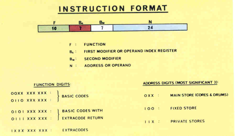
Each instruction is of the single-address type and refers to index registers Ba and Bm . F represents the function being obeyed and S is either a store address or in some cases a number of these 24 bits, the last three denote a particular 6-bit character within an address. The first bit is 0 if referring to a main store address (see diagram) or 1 if referring to a private store address. Normally a 1 in this position will be a program error and will cause entry to the supervisor. The only exception to this rule is if the first three bits indicate a fixed store address (i.e. if they are 100).
The function number is usually written as a binary digit followed by three octal digits (ranging from 000 to 1777). If the binary digit is 0 then a machine instruction is indicated; if 1 then an extracode entry is made, i.e. a built-in routine in the fixed store is entered although to the programmer it appears to be a single instruction. If the first four bits of an instruction (i.e. the binary number and the first octal number) are 0101 or 0111 and the instruction is being obeyed in an extracode routine then they cause return to the object program at the next instruction.
In an accumulator instruction, i.e. one which refers to the floating-point accumulator, the instruction is normally doubly modified, i.e. the content of both Ba and Bm index registers are added to the address (denoted by S) before the instruction is obeyed. For an index instruction, i.e. a B-type instruction, the contents of Bm are added to S before obeying and Ba is the index register on which the operation is being performed. Typical machine instructions are the following:
| 0122, 36, 0, 10 | this instruction subtracts the number 10 from B36 and leaves the result in B36 . |
| 0356, 0, 0, 5000 | place a copy of the contents of the floating point accumulator into store location 5000. |
| 1670, 0, 0, 1000 | put the sine of the floating point number in location 1000 in the floating point accumulator (extracode function) |
In order to test the size of an index without altering it, a special register is provided which can be used to record the sign and zero-equivalence of either s-b, b-s, n-b, b-n. This register is the B-test register Bt and four commands are available to test its contents bt , to see if it represents the states designated =0, ≠0, ≥0, <0. Typical of the instructions are:
| 0172, 56, 0, 7 | bt = b56 - 7 |
| 0224, 127, 0, 1000 | if bt = 0, i.e. if b56 = 7, place the integer 1000 in the main control register (B127 ). |
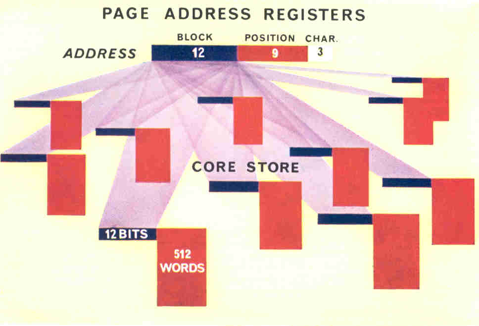
If one of these registers contains the number of the block in which the required word lies, recognition occurs and the corresponding page in the store is used for the command. Thus, so long as the required commands and their data are in the core store, access can be made at the full speed of the core store. If ultimately a word is called for which is not in the core store, then none of the page address registers signals agreement. When this happens the program is automatically interrupted and control is transferred to a special routine in the fixed store, called the drum transfer routine.
Each page address register is 12 bits in length, and the most significant bit is set only if the block is locked out because the particular program to which it belongs has been interrupted (see section on the supervisor). It is thus possible for programmers to use the same store address in different programs and be certain that they are completely independent.
To determine which block inside the core store is transferred to drum when a drum transfer is required a special routine is included in the supervisor known as the drum learning program. This seeks to arrange the programs inside the one-level store so as to minimise the drum transfers that take place when programs are obeyed. It will be noted that two successive blocks of program or data need not be in consecutive pages in the core store - the core store is in fact a set of pages the contents of which have been re-arranged into the most convenient order. The programmer, of course, need not be aware of this.
From the outset Atlas was designed as a multiprogramming machine. This is fundamental to the operation of the machine and is achieved by special hardware and by built-in program. This program is known as the supervisor and controls all the activities of the Atlas system including scheduling of programs and operation of all peripheral transfers.
In the past most computers have been only able to obey a single program at a time and this has meant that the operation time of programs has often been dominated by the speed of input and output. The first time-sharing machines, therefore, concentrated initially on autonomous operation of peripheral equipment. Even this is not sufficient with a machine of the size and speed of Atlas and it soon became clear that something of more advanced concept would be required. This was essential because many jobs on Atlas would run for only a few seconds and operators would be hard pressed to keep the machine fully occupied. Hence supervisor-controlled multi-programming is provided on Atlas.
The supervisor may be entered from an object program for on of the following reasons:
Program and data are divided into what are known as documents which can be put into the machine in any order. Each document may be a piece of program, an item of data or a job description, and must enter the system on a single input channel, although different documents can enter the machine at different times and on different inputs. The purpose of the job description is to give to the machine a list of all the documents required for that particular job and also, optionally, such data as estimated computer time and storage space. A typical job description would be as follows:
JOB
AUTOPROCESS 3
STORE 2
COMPUTING 10.0 SECS
INPUT
1 EXPERIMENT A
2 EXPERIMENT B
OUTPUT
1  TELETYPE 1 BLOCK
COMPILER MERCURY AUTOCODE
then the program itself terminated by
***Z
This tells the machine that it is to obey a program named AUTOPROCESS 3 which is written in Mercury Autocode. The compiler program will require at most 2 blocks in the main store and should run for no more than 10 seconds. There are two data tapes, named EXPERIMENT A and EXPERIMENT B, and output should be at most one block and it is required on a Teletype 110 ch/sec. paper tape punch. If the estimate for store used, computing time and amount of output are exceeded the program is interrupted and the operator informed. The ***Z signifies the end of the document to the supervisor.
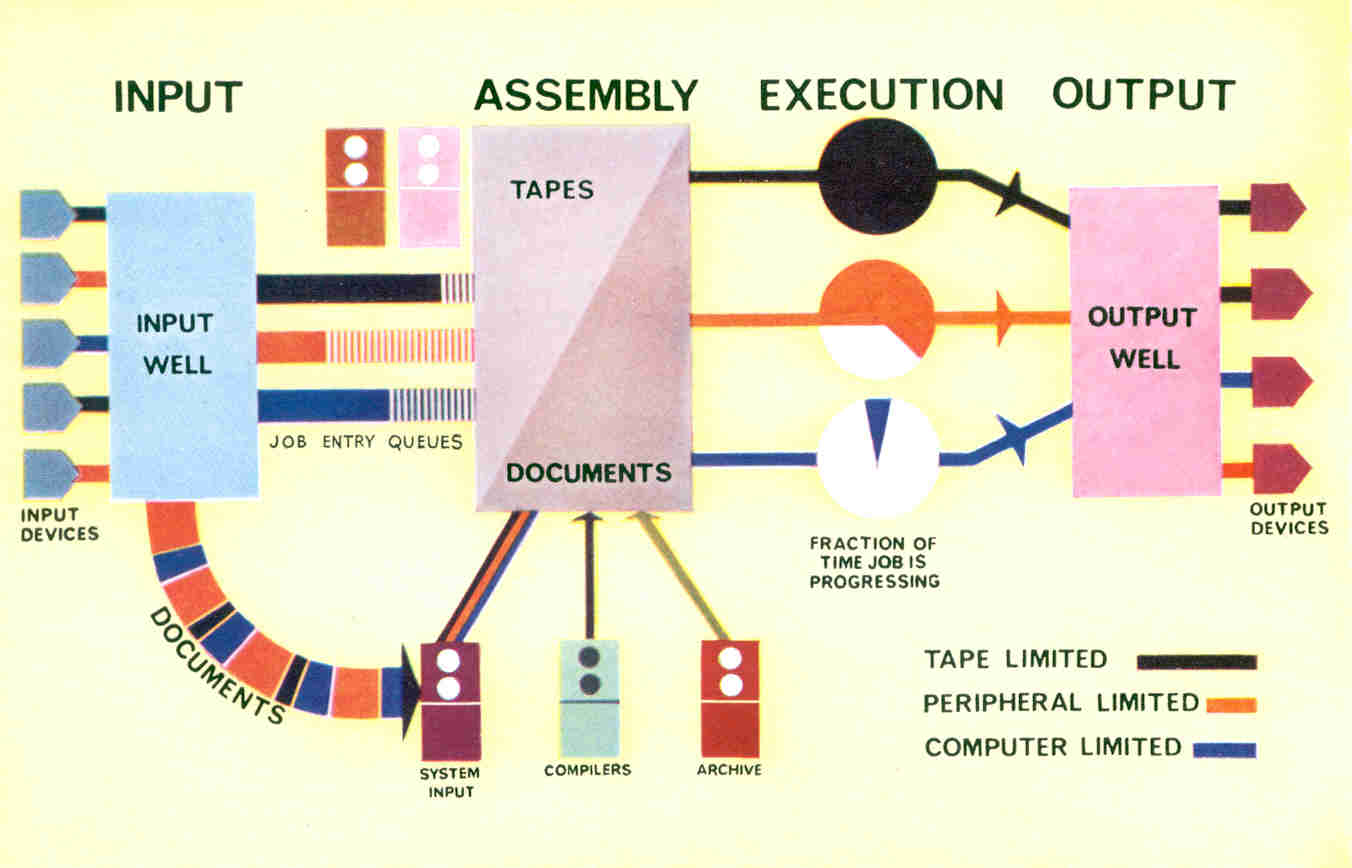
The operation of the supervisor is illustrated in Figure 9. An input well is reserved for all documents and consists of part of the main store together with a magnetic tape deck - the system input tape. When a job is complete, i.e. all the necessary documents have been assembled in the input well, the job is entered on one of three queues of programs waiting to be obeyed. These queues are for programs whose speed of execution is limited by the speed of magnetic tape, large computing jobs with a great deal of calculation, and small jobs.
One of the routines in the supervisor is the scheduler routine whose task it is to place jobs on the execution list - i.e. the list of those jobs actually being obeyed. Jobs will be selected which keep the machine and its peripherals as fully occupied as possible. When a job is completed it will be replaced by one from the appropriate queue. The actual order in which programs are put into the machine does not, therefore, determine the order in which they are obeyed, although this may be influenced by actions on the part of one of the operators.
Similar to the input well is the output well into which all output is fed by the computer. This consists of main store together with a system output tape. This well is emptied at rates appropriate to the particular output devices.
The size of these input and output wells varies depending on the mixture of programs being executed, and considerably helps to smooth out input and output to the machine.
Atlas provides an extremely powerful computing system able to take in every sort of job as it arises through whatever appropriate peripherals are free and to output the results in a similarly flexible manner. The work is automatically scheduled to make the best use of the system at all times. Such a system provides the ideal means of meeting the needs of the largest organisations, and of providing the most widespread computing service coverage in the most economical way.