
Atlas 2 is a new, smaller version of the Ferranti Atlas Computer. Atlas 1, the original version, was developed jointly by Ferranti Limited and the Department of Electrical Engineering at Manchester University, and represents a distinct advance in the world of computer design, not only in its size and speed but in the novel method in which the machine itself organizes its work to ensure the fullest possible utilization of all its component parts, enabling it to provide enormous computing power at extremely low cost per operation. The Ferranti Atlas Computing Service commenced work on the Manchester machine in January, 1963.
Atlas 2 has been developed in conjunction with the Mathematical Laboratory at Cambridge University, the site of the prototype machine. It reproduces many of the important features of Atlas 1, including the comprehensive time-sharing of programs and peripheral transfers. It is capable of speeds approaching those of the larger machine, and is thus suitable for an organization which can provide a high work load but does not require the extent of storage provided by Atlas 1.
The software provided for Atlas 2 will include, besides the semi-built-in Supervisor program for the overall control of the system, compilers for ALGOL, FORTRAN and COBOL. In addition, because of the high degree of compatibility in programming Atlas 1 and 2, many of the programs written for Atlas 1 will run on Atlas 2 with little or no alteration.
Although many readers of this document will be already familiar to a certain extent with Atlas 1, in what follows no knowledge of Atlas 1 is assumed; the larger machine is however mentioned wherever it is desirable to compare or contrast the two machines.
Atlas 2 has a main core store of up to 131,072 48-bit words, a floating point accumulator, and 128 24-bit index registers which may be used for double modification in an instruction. Index arithmetic is carried out by hardware separate from the accumulator; this and other provisions for overlapping operations enable Atlas 2 to complete up to half a million instructions per second (see the section below Speed of Operation for further details of speeds and how they are achieved).
All jobs on Atlas 2 are assembled on magnetic tape before their execution begins. The assembled jobs are scheduled for execution automatically, and at anyone time there will often be two or more jobs present in the main store under execution, sharing the time of the central computer according to predetermined priorities (which may however be altered during run-time if required). The output is distributed to the appropriate peripherals via magnetic tape. The work of assembly and scheduling of programs and control of time-sharing is carried out by the Supervisor program, which is permanently present in the machine and itself shares the central computer as it requires.
This system of automatic multi-programming makes Atlas 2 suitable for any type of computing job, whether small or large, whether limited by magnetic tape transfers or by computation. A job which takes less than a minute will be no more costly per operation than a job which runs for an hour or more. Moreover, the more varied the work to be done, the greater the probability that at anyone time a truly efficient job-mix can be achieved - that is, one which makes full use of all parts of the system.
It is anticipated that many prospective users of Atlas 2 will wish to employ a machine at some distance away. For this purpose it will be possible to establish data links or remote consoles for direct input to and output from Atlas 2; Ferranti Limited are at present developing equipment for data links, and a remote console may consist simply of a standard paper tape reader and punch. The use of satellite computers is also envisaged; the role of the satellite is to assemble complete jobs on magnetic tape for input to Atlas 2, and to accept the output for these jobs on magnetic tape and transfer it to appropriate output peripherals.
The Main Store of Atlas 2 is a core store of cycle time 2½ or 5 microseconds throughout, the access time being approximately half the cycle time in each case. Four independent access systems are provided, and are arranged so that any four consecutive locations in the store are accessed through different systems. In this way, delay while the cycle time is completed is often eliminated. The minimum size of main store is 32,768 full (48 bit) words, and this may be extended in units of 32,768 to 131,072 words.
In addition, there are three fast auxiliary stores.
The B-store, which contains 128 half-word (24 bit) index registers and has an access time of 0.35 microseconds. The B-store has its own arithmetic unit which is quite distinct from the floating point accumulator; thus indexing and floating point arithmetic may be executed simultaneously.
The V-store, a set of registers distributed physically in different parts of the machine, consisting mainly of information and control signals for magnetic tape and other peripheral equipments. The V-store also contains information enabling the Supervisor (see below) to exercise the full program and peripheral protection which is essential for a time-sharing system.
The Slave Store and Fast Operand Registers, consisting respectively 32 and 8 full length registers constructed of tunnel diodes. The slave store functions fully automatically in conjunction with the main store in such a way as to ensure that any small loop of instructions is held in the slave store during its execution. A fuller explanation of this process is given in the section below entitled Speed of Operation.
The 8 fast operand registers appear to the programmer as the first eight locations of this program region, and the effect of using one of these locations for an operand is to reduce store access time effectively to zero and also to relieve the core store access systems.
The organization of the Atlas 2 storage system as a whole is shown in Figure 1. This diagram also indicates the method of controlling magnetic tape and peripheral transfers.
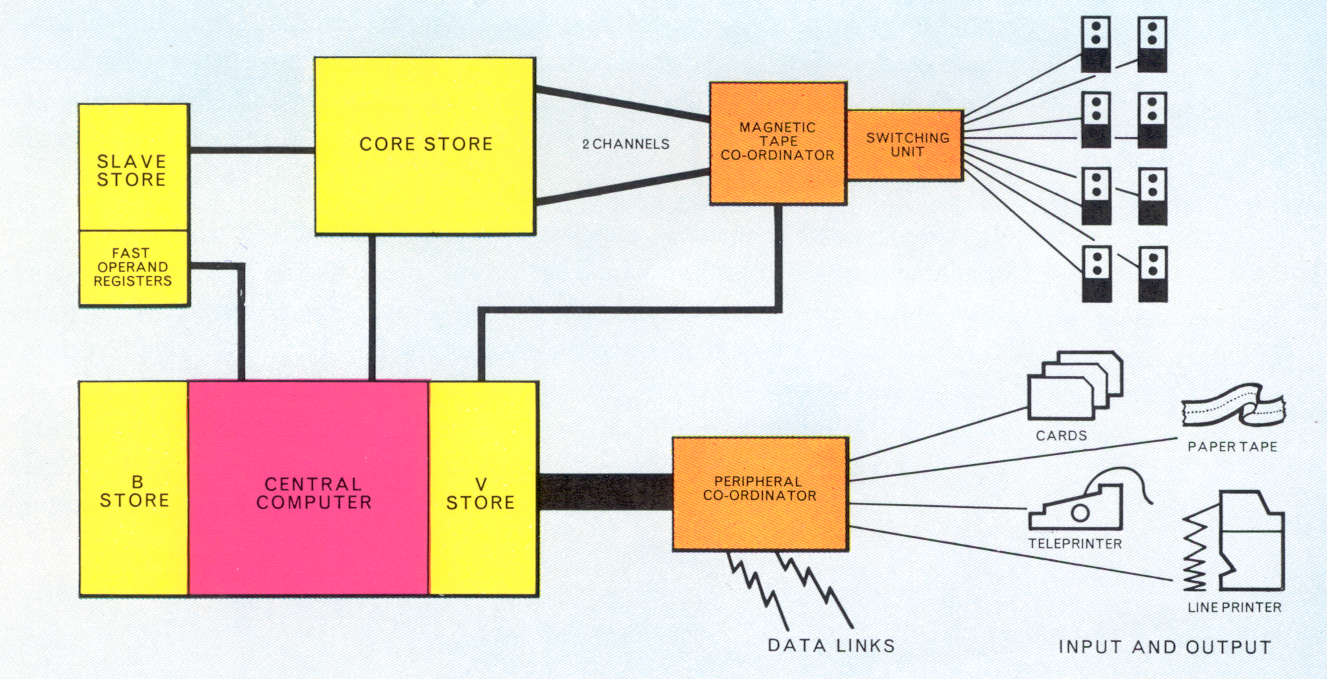
The speed of Atlas makes it possible to simplify the method of attaching peripheral devices. Magnetic tape transfers are handled by a Magnetic Tape Coordinator (see the Section below The Magnetic Tape System), and all other transfers are controlled by a single Peripheral Coordinator. Whereas in other large machines sections of information are transferred by special control units, in Atlas transfers are carried out by small interrupt programs which form part of the Supervisor. The unit of information will be either one or a small number of characters depending on the nature of the peripheral; the proportion of the central computer's time taken up during transfer on a single peripheral will not exceed a few per cent e.g. about 3% for a 1000 char/sec. paper tape reader.
The design of the Peripheral Coordinator provides a large number of input and output channels; the standard capacity of each channel is 12 bits, but it is possible to extend channels from 12 to 24 bits as required. The number of channels provided is sufficient for all likely configurations. For instance, an installation with 6 paper tape readers, 6 paper tape punches, 2 card readers, 1 card punch and 4 line printers would still have considerable spare capacity. Most of the standard devices used with Atlas have speeds of up to about 1,000 characters per second. Much faster devices than this can however be attached, and in limiting cases special channels are available permitting devices to operate up to the maximum transfer rate of the core store.
Input and output is normally via 7-channel paper tape but 5-hole tape may also be used. The readers which can be attached are the Ferranti TR5 and the Elliot Type D4/32, which operate at maximum speeds of 300 and 1,000 char/sec. respectively.
Output can be either by the Teletype 110 or by the Creed 3000 punch, with maximum speeds of 110 and 300 char/sec. respectively.
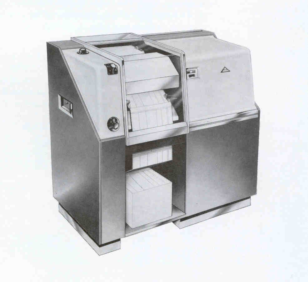
The standard card reader on Atlas is the I.C.T. 593, which has a maximum speed of 600 cards/minute.
The standard punch is the I.C.T. 582, operating at 100 cards/minute. Both these devices operate on 80-column punched cards.
The Anelex 4/1000 printer has been adopted as standard on Atlas. It has a maximum printing speed of 1,000 lines/minute, achieved when the characters used all belong to the restricted 48-character set. Any line containing one of the further 16 available characters takes longer; the minimum speed is 815 lines/ minute. There are 120 printing positions on a line. This printer is illustrated in Figure 2.
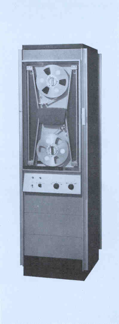
Atlas 2 is equipped with Ampex TM2 magnetic tape decks, illustrated in Figure 3, operating with 1in tape. A minimum of two channels is provided, together with one two-by-eight switching unit which allows the attachment of up to eight tape decks any of which may be selected for a transfer on either channel. Two further channels may be added, which with the addition of a second switching unit can accommodate a further eight decks. Alternatively, the switching units may be used as one-by-eight, so that with four channels and four switching units a total of 32 decks may be attached. On each channel one reading, writing or search operation may proceed independently of the other channels, and in addition, long searches, once initiated, may proceed off-channel. Reading may be carried out either forwards or backwards, but writing can only take place in the forwards direction.
The tape is divided into blocks of 512 48-bit words, enabling about 5,000 blocks, i.e. 20 million characters, to be held on one 3,600-ft. tape. There are 16 tracks across the tape of which 12 are for information. A 48-bit word is therefore represented by four 12-bit stripes across the tape. At the end of each block is recorded a 24-bit checksum, and each block is preceded by a block marker and block address and terminated by a trailing block marker. The speed of the tape is 120 in/sec. which implies an instantaneous transfer rate of 90,000 char/sec. The effective transfer rate, i.e. the rate allowing for the gap between blocks, is 64,000 char/sec. This means that if purely numerical data is present on the tape in binary (a more efficient form of storage) the instantaneous transfer rate is equivalent to 120,000 decimal digits/ second.
All tape transfers are of 512 word blocks, and after initiation are carried out autonomously between the magnetic tape coordinator and the core store without requiring any action by the central computer. Thus programs may proceed without any interruption during the transfer of a block, except for hesitations resulting from the simultaneous access of the transfer and of the programs to the core store. The maximum hesitation is one core store cycle time, either 5 or 2½ microseconds, during the transfer time for each full word, on average 125 microseconds. Thus programs may be slowed by a factor of up to 4% or 2% (according to the store cycle time) for each transfer proceeding; in practice the factor will be normally a small fraction of this.
A 5l2-word block transfer may involve a single section of core store starting at any address, or may be scattered over the core store in blocklets of 64 words; during any transfer the part(s) of the core store involved are locked out to ensure that they are neither read nor written to by program during the transfer. A full range of extracodes (see below, Atlas 2 Programming) is provided to control magnetic tape transfers. Among them is a group which enables the programmer to carry out variable length transfers; he may simulate the reading and writing of variable length blocks separated by markers defining the block lengths, and the Supervisor program uses a store buffer (specified by the programmer) to execute the appropriate fixed length block transfers to and from the tape as required.
All tapes are pre-addressed before they are used, either by a special run on the computer or by a pre-addressing machine. During this process any faulty sections are found and are left unused. If a checksum failure occurs for any transfer, further attempts are made to carry out the transfers, and if one of these succeeds the program is allowed to proceed, monitoring information being printed to inform the engineers of the error. Otherwise the operator will be instructed to remount the tape on another deck in case the first deck is faulty. If all attempts to complete the transfer fail due to a faulty section of tape, the program is suspended and the mechanism disengaged. If the intended transfer is one writing to tape, the program may be allowed to continue after the intact portions of the tape have been copied to a new tape.
I.B.M. ½ inch magnetic tape can be attached to Atlas 2 via the magnetic tape coordinator. A special additional control unit enables up to five 729 MK IV decks to be connected to anyone channel, either directly or through one of the existing switching units. Only one of these decks could be in operation at any one time.
The format of the tape is standard I.B.M. i.e. variable length records with lateral and longitudinal parity.
A disc store with a capacity of up to 12 million words can be attached. Transfers will be in units of one or more 5l2-word blocks. The revolution time is 50 milliseconds, and during this time 8 blocks, i.e. 4096 words can be transferred. For a file with n discs, 8n blocks are available without head movement; to move the heads to other blocks, between 30 and 180 milliseconds is required.
The general channels on the peripheral coordinator can be used for the attachment of a wide range of special devices. Examples are: a low speed display unit, with a speed of 2 co-ordinate points per second and accuracy 0.02in, and a high speed display unit capable of accepting 200,000 points per second with camera shutter and wind controlled by the computer.
An artist's impression of a typical Atlas 2 installation is given on the centre pages of this document. A typical installation may comprise the following equipment besides the Central Computer, with B-store and V-store:
Slave store and fast operand registers.
The extent to which the equipment may be varied is given in other sections of this document.
It will be noted that the paper tape peripheral and teleprinters are shown grouped on consoles in the diagram. This arrangement is not obligatory, indeed it may be more convenient for an installation to group together all paper tape readers and all paper tape punches respectively, with the exception of a master tape reader which would be conveniently grouped with at least a teleprinter and an off-line Flexowriter on a Main Operators' console. The 3 Teleprinters are respectively for the Main Operator, the Engineers and the Magnetic Tape system and should be conveniently sited to fulfill these functions; thus an Engineers' console may comprise one TR5 paper tape reader, the Engineers' Teleprinter and the Engineers' panel. It is also possible that the number of Teleprinters be reduced, one Teleprinter serving for example for both the Engineers and the Magnetic Tape operator.
A remote console, for input and output at a remote station, would normally comprise a paper tape reader and a paper tape punch.
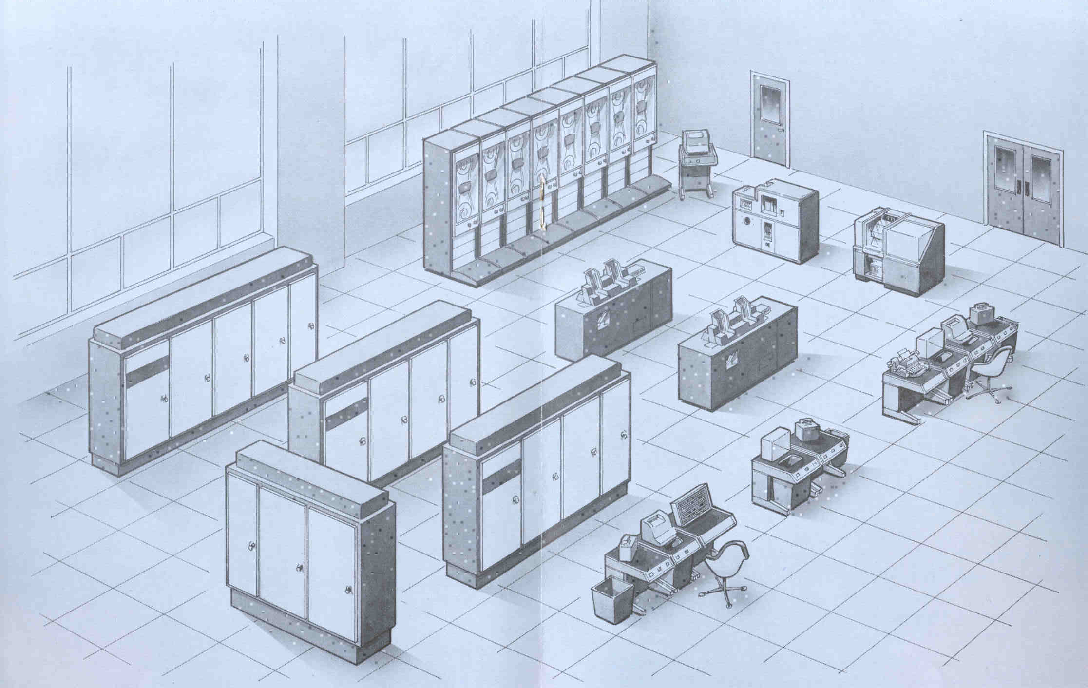
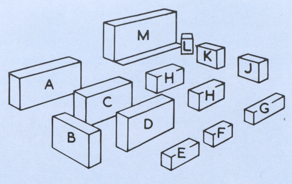
A  Power Supply
B  32K Core Store
C  Tape and Peripheral Coordinator and Switching Unit
D  Central Computer
E  Engineers' Console with -
   TR5 Tape Reader
   Creed 75 Teleprinter
   Engineers/Switch Panel
F  Auxiliary Console with - Teletype 110 Punch
   and TR5 Tape Reader
G  Master Console with -
   Flexowriter Teletype 110 Punch
   Creed 75 teleprinter
   TR5 Tape Reader
H  2 - ICT Type 593 Card Readers
J  Anelex Line Printer
K  ICT Type 582 Card Punch
L  Magnetic Tape Operators' Teleprinter
M  8 - Ampex IBM Tape Units
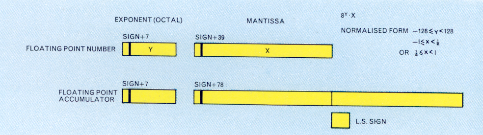
The Atlas 2 word length, excepting the B-store, is 48 bits, each 24-bit half-word having a parity bit associated with it. The word can be thought of for example as a single-address machine instruction, 8 characters of 6 bits each or as a single floating point number, as shown in Figure 4.
In the Atlas 2 representation of a floating point number 8 bits are used to represent the exponent y and 40 bits the mantissa and sign x. The exponent is an octal one and the number represented is therefore x.8y. Twos complements are used for negative numbers, so that when normalised, ⅛ ≤ x < 1 or -1 ≤ x < ⅛ and -128 ≤ y < 128. Floating point arithmetic makes use of a floating point accumulator, in which the mantissa is double length (sign and 78 bits).
It is anticipated that a large proportion of the work on Atlas 2 will be programmed in the problem oriented languages, FORTRAN, ALGOL and COBOL, for which compilers are provided. A symbolic assembly program known as ABL, (Atlas Basic Language) is also provided; this is basically an external form of the machine code, with the addition of facilities for extensive use of parameters and for input of data in many forms - e.g. floating point numbers, half-words and characters. The remainder of this section is a brief description of the basic machine code.
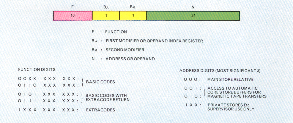
A single instruction on Atlas 2 is 48 bits long. It is divided up into four parts as shown in Figure 5. Each instruction is of the single-address type and refers to two index registers Ba and Bm. F represents the function to be obeyed, and S is either a store address or a number. If it is an address, of the 24 bits the last three are used with some instructions to denote a half-word or a particular 6 bit character in a word. The next 18 bits constitute the word address, and the three most significant bits determine the type of address. The programmer may only use addresses whose first bit is zero; a one in this position will normally cause monitoring information to be printed. The address used by a programmer will usually have its first three bits zero and will be treated as a relative address (see Storage Allocation and Time Sharing); the other two possibilities (shown in Figure 5) permit access to one of two particular regions of his program space which are treated as automatic buffers for magnetic tape transfers.
It should be noted that this method of decoding addresses enables programs written for Atlas 1 to be run on Atlas 2, provided only that the addresses are not too large.
The function number is usually written as a binary digit followed by three octal digits (ranging from 0000 to 1777). If the binary digit is 0 then a machine instruction is indicated; if 1 an extracode entry is made, i.e. a built-in routine is entered although to the programmer it appears to be a single instruction. If the first four bits of an instruction (i.e. the binary number and the first octal number) are 0101 or 0111 and the instruction is being obeyed in an extracode routine then they cause return to the object program at its next instruction.
In an accumulator instruction, i.e. one which refers to the floating-point accumulator, the instruction is normally doubly modified, that is, the contents of both the Ba and Bm index registers are added to the address (denoted by S) before the instruction is obeyed. For an index instruction, i.e. a B-type instruction, the contents of Bm are added to S before obeying and Ba is the index register on which the operation is being performed. Typical machine instructions are the following:
0122,   36,    0,  10    - this instruction subtracts the number 10
                           from B36 and leaves the result in B36.
0356,    0,    0,  5000  - place a copy of the contents of the floating point
                           accumulator into store location 5000.
1670,    0,    0,  1000  - put the sine of the floating point number in location
                           1000 in the floating point accumulator
                           (extracode function) .
In order to test the size of an index without altering it, a special register is provided which can be used to record the sign and zero-equivalence of either s-b, b-s, n-b, or b-n, where s, b are the contents of a main store register and an index register respectively, and n is an integer. This register is the B-test register Bt and four instructions are available to test its contents bt, to see if it represents the states designated = 0, ≠ 0, > 0, < 0.
Typical of the instructions are:
0172,   56,     0,   7    - bt = b56-7
0224,  127,     0,   1000 - if bt = 0, i.e. if b56 = 7, place the integer 1000
                            in the main control register (B127),
                            i.e., jump to location 1000.
A primary aim in the design of Atlas is to ensure that the fast logic of the central computer, including the accumulator and the B-arithmetic unit, is left idle for as little time as possible. The means by which this is achieved are various. First, by time-sharing, the Supervisor ensures that no delay results from peripheral transfers or magnetic tape transfers, or on completing execution of a program. Second, by a combination of the features described below the delays which result from the access and cycle time of the main core store are reduced to a minimum. Therefore, although these times (2.2 and 5, or 1.l and 2.5, microseconds respectively) are slow compared with other basic times in the machine, for example 0.35 microseconds to access an index register or 0.6 microseconds to decode an instruction, speeds are achieved which in many instances approach the speed of Atlas 1.
The obeying of instructions can be divided into five distinct stages though some of these stages are absent in some instructions:
For anyone instruction these operations must be in strict sequence, and for a floating point addition this can give a total execution time of 7 to 8 microseconds. This however represents only about one third of the rate at which instructions are completed, since in general there will be three instructions at different stages of execution at any moment. For example, for three instructions I1, I2 and I 3, the arithmetic for I1 the B-modification for I2 and the extraction of I3 from the store may all proceed simultaneously. The sequence may be seen clearly and in greater detail in Figure 6.
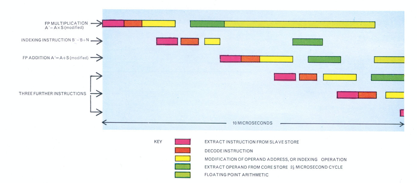
Much of the advantage of instruction overlap can be lost, however, if it is necessary to wait a full core store cycle time of 5 microseconds between extracting the successive instructions I1 and I2 or (even more serious) between extracting I2 and extracting the operand for I1. To obviate this delay in most cases, the core store is divided into four stacks (interleaved so that locations 0 (mod 4) form one stack, locations 1 (mod 4) the second, and so on), and each stack is served by a completely independent access system. Thus the core store cycles of different stacks may be overlapped, which implies that accesses for consecutive instructions will never clash, and that there is a reasonable chance that an access for an operand will not cause a clash.
A delay of a complete store cycle time is thus frequently eliminated, but the access time of 2.2 or 1.1 microseconds, if always present, would still impair the balance of the machine (due to it, the central computer would be too often idle). The main step in achieving balance is the introduction of the 32-register Slave Store.
At any moment a particular register N of the slave store contains an instruction whose main store address has its least significant 5 bits equal to N, together with the 12 most significant bits of its address. Before any instruction is extracted from the main store, the 12 most significant bits of its address are compared with the 12 address bits in the appropriate slave store register; if there is agreement the instruction is extracted from the slave store and access to the main store is not made. If there is no agreement, the instruction is extracted from the main store and as it is obeyed it is written to the appropriate slave store register together with its 12 most significant address bits.
It must be emphasized that, in the case of no agreement, the instruction time is no greater than if there were no slave store. When the instruction is found in the slave store, the effective access time is simply the time required to compare the 12-bit addresses - about 0.2 microseconds.
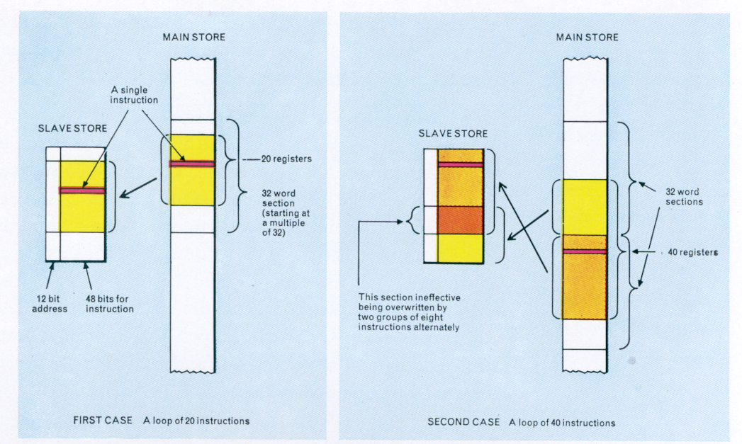
The effect of the slave store, as illustrated in Figure 7, is that any continuous loop of 32 instructions or less is obeyed on the first iteration from the main store and on subsequent iterations from the slave store. Thus for the considerable proportion of programs which spend a large fraction of their time (in some cases practically 100%) in small loops, the slave store is fully effective. As the loop size increases from 32 to 64 instructions, the effect decreases steadily to zero. An example in this range (40 instructions) is also shown in Figure 7. An additional advantage is that the stack access systems are relieved, reducing further the possibility of a stack clash.
The programmer need have no knowledge of the existence of the slave store, and has no control over its operation.
What the slave store does for instructions, the 8 fast operand registers do for operands. Here, however, the programmer has control; these eight registers are known to him as the first eight locations of his program, with addresses 0 - 7. He may, but need not, use these locations to store operands requiring repeated access, e.g. the partial sum in the scalar product of two vectors. The effective access time of these registers is zero, and (equally important) their use further reduces the chance of a stack clash.
The fastest version of Atlas 2 will be that equipped with the core store with a 2½ microsecond cycle time. The table which follows gives approximate comparative speeds for some specimen operations.
In the table which follows, the first and third columns give times which assume use of the slave store and fast operand registers, while those in second and fourth columns assume neither. Times are given in microseconds.
| Operation | 2½ microsecond store |
5 microsecond store |
||
|---|---|---|---|---|
| Single instructions | ||||
| Repeated indexing operation or floating point addition | 2.0 | 2.8 | 2.0 | 4.6 |
| Repeated floating point multiplication | 5.0 | 5.0 | 5.0 | 5.5 |
| Repeated floating point division | 10.7 to 29.8 | |||
| Simple loops | ||||
| Scalar product of two n-vectors | 11.9n | 15.0n | 14.3n | 25.9n |
| Sum polynomial to n terms | 7.4n | 9.2n | 8.3n | 13.7n |
Time-sharing on Atlas takes two forms. First, the peripheral devices including magnetic tape are able to operate concurrently with the execution of program, since a peripheral transfer once initiated can proceed autonomously, and will signal its completion by an interrupt. Second, under normal operating conditions often two or more programs will be present simultaneously in the main core store so that when one program is held up for a magnetic tape transfer the Supervisor will switch control to another program, the time for the switch being of the order of one millisecond. The Supervisor will normally ensure that only one magnetic tape limited job, that is a job whose total tape-transfer time exceeds its computing time, is present in the core store at any time. This technique is known as multi-programming, and it must be emphasized that it is implemented entirely by the Supervisor; the programmer need have no knowledge that his program is being executed concurrently with another.
Closely associated with time-sharing is the system of storage allocation and protection. Each program is written using addresses numbered from zero; when it is brought into the main store for execution it is allocated a section of the main store (a multiple of 512 words) sufficient for its operation, and the program addresses (which appear to the programmer as absolute) are interpreted by the hardware as relative to the base address of the allocated section. Any reference by the program (due to a program error) to an address outside the allocated section will be locked out; the Supervisor will cause monitoring information to be printed and will normally suspend the program, to make room for another program and to ensure continued efficient operation of the system. By this means it is ensured that no program is violated by errors in another program. In addition, a region within the program which is currently involved in a magnetic tape transfer is protected in a similar way from access by the program; an attempted access to this region will cause a switch to another program, and the execution of the first will be resumed on completion of the transfer.
The Supervisor Program, although not built in to Atlas 2 nor stored in a fixed store, must be regarded as a fundamental part of the complete computing system. Much of the hardware of the machine has indeed been provided expressly for the use of such a program, and the machine would therefore not be fully exploited without its incorporation. The purposes of the Supervisor include the scheduling of jobs for execution in such a way as to ensure efficient time-sharing of all parts of the machine, the implementation of time-sharing (involving for example the switch from one program to another due to a magnetic tape transfer), two-way communication with the operator (for example, instructions concerning the loading of peripherals or alterations in the execution priorities accorded to programs), the periodic initiation of routine engineers' test program, and the logging of programs for accounting purposes.
The Supervisor occupies a minimum of about 5,000 words of core store, but is capable of expansion to about 16,000 words if the current store usage allows, the additional routines being brought down from magnetic tape and having the effect of increasing the power and flexibility of the system. If a large job occupies the machine for a considerable length of time the Supervisor will only demand its minimum space of 5,000 words, but with a fairly frequent type of work-load comprising medium and short jobs with various peripheral and magnetic tape requirements the Supervisor may use about 8,000-10,000 words. It adjusts its own size completely automatically to suit the current work-load.
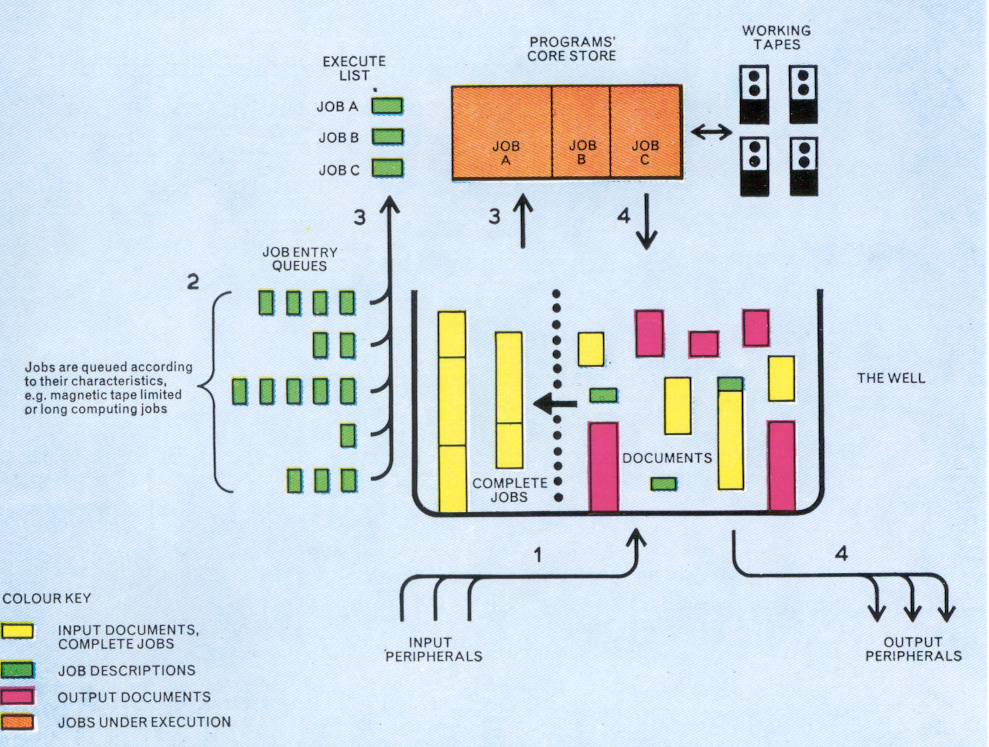
Similarly, the Supervisor normally requires a number of magnetic tape decks for its own use, but the number required is automatically adjusted to suit the present activity. Among the uses to which the Supervisor puts magnetic tapes are the combined Input/Output Well, and Working Space tapes for Compilers and object programs. The Input/Output Well embodies a sophisticated use of any number of tape decks from 0 to 4, in conjunction with a section of core store, to accumulate all 'documents' entering the machine via the slow peripheral equipments until they can be assembled into complete jobs for execution, and similarly all material produced by programs and waiting for output. The Well is capable of expansion to a considerable size, even with one or two tape decks and a comparatively small core store buffer; for example, with a total average data rate of 1,000 characters per second (combined Input and Output) through the Well with a core store buffer of 3,000 words and two tape decks a Well capacity of about 200,000 words is achieved. This is capable of absorbing very pronounced peaks in input and output without disturbing the work of the central computer, which is the execution of programs. The Working Space tapes provide the facility for a programmer or a Compiler to request space on a tape rather than requesting a complete private tape, which can be a source of inefficiency in the use of magnetic tape equipment.
Entry to the Supervisor, i.e. interruption of the current program, may be any of the following causes:
It is not possible in the present document to describe all the functions of the Supervisor. The following section, however, deals with one of its most important operations, that of ensuring that the right job is done at the right time.
All jobs are divided into Documents which may be either program or data; a document is the unit of input to Atlas. The documents which comprise a job may enter the system on different input peripherals, but each document must enter on one single peripheral. They may be input in any order, except that the first document for each job must be, or contain, a Job Description whose purpose is to provide the Supervisor with the information needed to assemble the job and to schedule it efficiently for execution. Items which may appear in the job description include:
As explained above, all documents received are placed in the Well and listed by the Supervisor so that when all the documents required by a job description are present the job may join one of the queues of jobs waiting to be obeyed. There are separate queues for jobs according to their characteristics, e.g. for magnetic tape limited jobs or jobs which use a particular peripheral extensively. When a new job is required on the execute list, i.e. the list of jobs currently being obeyed, the Supervisor will normally select the job at the head of the appropriate queue; which queue is appropriate is determined by, among other factors, the set of jobs at present on the execute list and the distribution of the load on the output peripherals. If a program is accorded a priority other than normal, by an operator's request, the Supervisor will take note of this in scheduling jobs for execution.
A consequence of the method outlined above of controlling the input, execution and output of jobs is that at any moment there are three sets of jobs in the system: those present (perhaps still incomplete) in the Well awaiting execution, those under execution, and those whose execution is complete but whose results are still wholly or partly in the Well awaiting output. The output for a job on slow peripherals may, but need not, commence before its execution is complete.
Figure 8 illustrates the main features of the flow of jobs through the system.
The fundamental assumption which has shaped the design of the Atlas 2 computing system, hardware and software together, is that economy of computing is not realized by expensive hardware unless it is ensured that this hardware is fully active for the maximum proportion of time that the system can achieve. The result is a truly general-purpose computer - one that is as efficient for small or large jobs, and which can adapt itself dynamically to each configuration of jobs as it arises.
