
The Operators use of the Atlas Console is limited to what they can see on the black and while monitor screen. The three sets of lights at the top are the main interest.
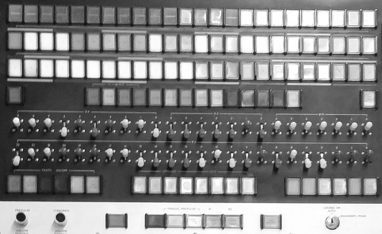
The third row from the top contains the octal contents of register B120. That is all it does. Writing some contents into B120 effectively gives a message to either the operators or the engineers An example of a display is shown above. In normal operation, the Supervisor displays the current state of jobs on the machine in B120. Starting at the far left, there is a sequence of bits that give information about the job queues. When set they mean:
Bit   Description
23    Top Priority Jobs running
22    Tape jobs running
21    Short jobs generating lineprinter output
20    Short jobs generating 7-track punch output running
19    Short jobs generating 5-track-punch output running
18    Short jobs generating card punch output running
17    Long jobs running
6-11  Number of jobs completed since last start
0-5   Number of Jobs, input complete, and running
The photo above indicates that most of these operations are taking place. The number of jobs completed since last start is 56 (modulo 64)
The fourth row is primarily concerned with parity checking. The first 13 lights in the middle show if a parity error has been detected. The first four indicate errors in the even and odd addresses and operands in main core memory, the next two transfers to and from the drums, and the next three for various magnetic tape activities, the final four for the special stores in the Atlas architecture, the 14th light in the middle is a spare. The first button on the left resets all the indicators back to off. The light on the far right used to be the 14th but got moved to indicate it was different from the other 13. It indicates the machine is running in normal mode and not being investigated by the engineer.
The two rows of 24 switches allow the engineer to set up a machine instruction to be executed for debugging purposes. The top row consists of the 10-digit instruction code followed by the two 7-bit index registers Ba and Bm. The second row defines the instruction address. For example:
121 127 0 address
Would define a jump instruction to the address specified. The engineer could then execute instructions one at a time from that position hopefully finding out what the error under investigation was caused by.
The final row with black background give assistance to the engineer when investigating a fault. The set of six to the left allow the engineer to switch parity checking circuits on and off. The eight operand buttons in the middle control digits in Atlas's V-store which are normally set by a peripheral when it requires attention. This allows the engineer to simulate peripheral activities. The six buttons to the right are spare (originally they were the buttons in the section of the console with a white background).
The final row with a white background give the engineer further controls. The two controls on the left adjust the volume of the hooter attached to the oscillator when a prepulse is obeyed and the oscillator attached to an entry in the V-store. The engineer can step through instructions one at a time, slowly or at normal speed and these generate different sounds in the prepulse hooter. The V-store hooter indicates V-store activity.
The first button by itself is the RESET button which is normally just used when the Atlas is switched on to reset certain stores and registers.
The next set of five define:
ENG INT
SINGLE
100KCS / STOP
AUTO / MANUAL RATE
AUTO / MANUAL ORDER
ENG INT, the engineer's interrupt button, is normally used for starting up engineer's test programs.
SINGLE causes an instruction to be obeyed each time the button is pushed.
100KCS allows instructions to be obeyed one at a time with no overlap at a slow speed. This is a double action button so it can also be set to STOP which just stops once the instruction has been obeyed.
AUTO ORDER indicates the instruction being obeyed is from the store and AUTO MANUAL indicates the instruction obeyed is from the hand keys.
AUTO RATE indicates the nornal rate of instructions is being obeyed while AUTP MANUAL indicates it is either working at the 100KCS or SINGLE modes.
The final button by itself STOP HALF ADDER stops the normal action of executing the next instruction or the one jumped to. Instead it keeps the instruction counter set to the current instruction allowing the engineer to repeatedly execute the same instruction.
Finally the key at the end is normally set to AUTO but switched to engineer's mode when the engineer is conducting any of the activities described.
