
Readers will recall from recent issues of ECN that the Engineering and Physical Sciences Research Council (EPSRC) has been undertaking a review of the EASE Programme. EPSRC has now informed us of the outcome of this review. Approval has been given for us to include here the following relevant extracts from their letter to inform ECN readers of the outcome.
EPSRC has decided not to continue to support an ongoing, centrally funded EASE Programme beyond 31 March 1996. In reaching this decision, which has the agreement of the Director, Engineering and Science, and the Chief Executive, the Council took into account the results of the recent survey of grant holders; consultations undertaken by relevant EPSRC Programme Managers within their respective communities; and competing demands on EPSRC Programme funds.
The Council is however prepared to provide some support to the Council for the Central Laboratory of the Research Councils (CCLRC) for the three existing Community Clubs (in Computational Fluid Dynamics, Visualization and Parallel Processing); on a reducing basis over the next two years, to assist a transition whereby the activities of these Clubs are subscribed to directly by interested researchers who can include the cost, if justified, in their grant proposals. The Clubs, if required, would then effectively become self-supporting.
No specific support would be provided over the next two years for the general Education and Awareness activity, including the newsletter, Engineering Computing Newsletter. However, the Community Clubs would of course be free, either separately or jointly, to issue newsletters centred on their activities.
We have now confirmed CCLRC's acceptance of the support offered for the Community Clubs over the next two years as described above. The details of the activities to be carried out by the Clubs with this funding, the issue of self-supporting status and the mechanisms for communicating with Club members will be addressed by the respective Steering Groups before the end of January.
As a result of this decision this will be the last regular issue of ECN. We will be publishing a special final edition in late January/early February which will reflect on the last 20 or so years since the RAL-based central support for engineers began in 1975. It will also report on any decisions reached by the Community Club's Steering Groups, if these are available in time. We would also like to invite contributions (up to 500 words) from any readers who feel they would like to contribute to this final issue of ECN (it is appropriate that the final issue will be number 60!!).
Such contributions should reach the Editor no later than Friday 5 January.
Opportunities and Problems in the simulation of Power Electronic Devices and Circuits Seminar on 15 January 1995 at the Manor Hotel, Meriden, Solihull, Nr Coventry.
The Power Electronics Circuits and Sub-Systems Sector in the UK is strong, and a series of collaborative Research Programmes under one of the directed LINK schemes have been undertaken over the last few years.
That scheme has now formally closed and it is timely to consider how academic/industry interaction might best be formulated in the wake of this Programme.
Developments in Software Support have been considerable over the period of the Programme. Yet the uptake by industry, and particularly SMEs has been minimal. The potential for such software to increase the efficiency of the design process is substantial, but the financial and time pressures on companies makes it difficult for them to take advantage of such design aids.
Following a review of existing tools, the seminar will focus on the concept of a linked academic/industry distributed design centre as a means of providing an effective modelling service to the industries involved.
Traditional CAD software has certainly had a profound impact on design. But in some respects it has done no more than replace the mechanical drawing board with an electronic one. Indeed such systems have little or nothing to assist the designer in the conceptual stage of the design process. This is unfortunate, as it is at the all important stage where each decision taken has effects more profound on the design than in any subsequent stages. Yet it is at this very stage that the designer has to explore alternative design possibilities, and take decisions based on information which at most is imprecise and uncertain.
The work described here is a software package, developed at the Engineering Design Centre at Cambridge University, for supporting this synthesis and exploration process. The software synthesises a series of mechanical design concepts when presented with the required input-output functions of a design, and allows the designer to explore these concepts before homing in on the most promising ones for further development. Its applications span devices and machines which involve motion.
The underlying principle can be noted from an initial examination of several mechanical devices and machines. Many of the components are essentially the same: cams, shafts, tie-rods, etc. This means that if the characteristics of these components can be mathematically represented by using some basic parameters, and if these parameters could be intelligently combined by a computer, the computer would be able to synthesise complete designs using the above knowledge.
This is exactly how the software works. Its knowledge-base contains a set of basic elements and rules governing their operation and combination; the software can combine these elements together to solve a range of design problems, so to generate not only those solutions from which these elements and rules were extracted in the first place, but also other novel designs.
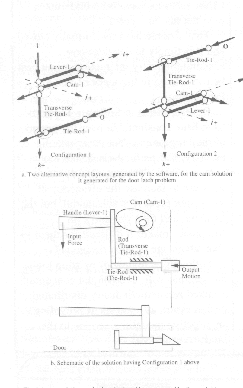
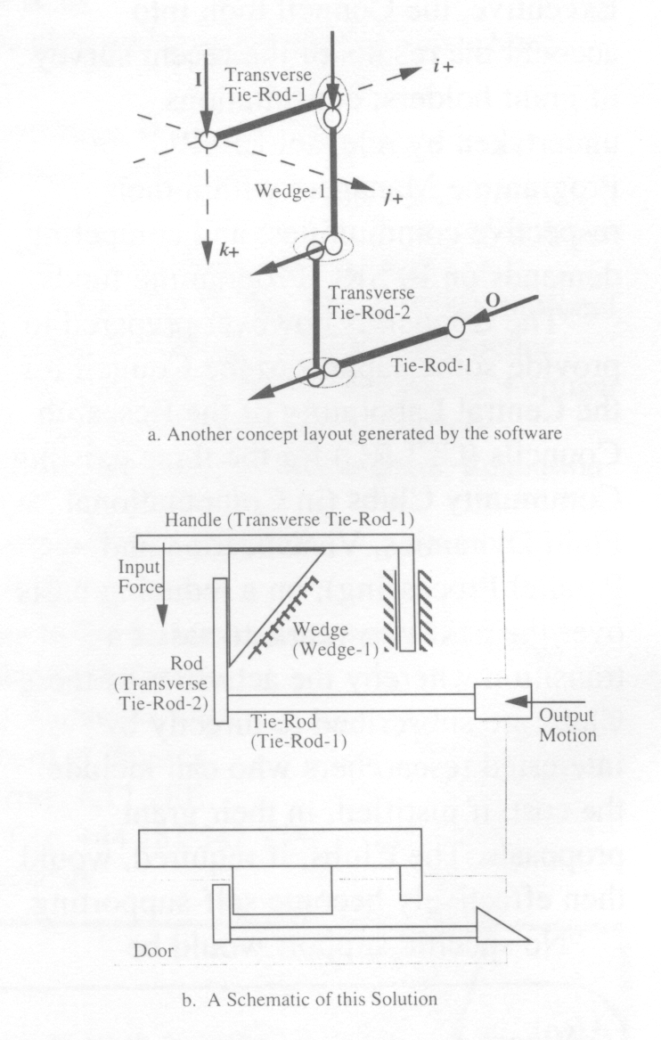
To demonstrate this, take the example of the design of a door latch. One principle of its operation is that when a handle is pushed down, there is a (dis)engagement between a frame and a door. One well-known way to achieve this is to have a design which (dis)connects an object that protrudes into the frame. In terms of motion, an input motion in a vertical direction is used to produce an output linear motion in a certain horizontal direction. Given this as the required function, the computer generates a series of designs, and a series of alternative layouts for each such design, to satisfy this requirement. One such design is where the vertical push on a handle rotates a cam which pushes out the lock (Fig. 1). Most door latches in England are based on this concept. But the software generates other designs too, including one where when a handle is depressed, a wedge moves down and moves out the lock - an entirely different solution to the problem (Fig. 2). And the software has demonstrated that there are not just these two solutions to this problem, but at least fifty.
The effectiveness of the software has already been demonstrated in the design of an arm support for muscular dystrophy sufferers. While a group of engineers at Cambridge designed an arm support using conventional techniques, this software was used to independently offer up a set of alternatives. Results? The designs suggested by the software included the solution developed by the designers as well as other ones, some with fewer components, thereby reducing much of its cost and redundancy.
The design research group in the Department of Computing and Information Systems is currently carrying out research within two DTI-EPSRC programmes, Safety Critical Systems and Computer Support for Cooperative Working. The projects are Safety Critical Integrated Design Support (SCIDS) and Designers Using Cooperative Knowledge (DUCK).
Both projects will use an Online Design Journal (ODJ), which is designed to replace the pen/pencil and paper day book or journal used in one form or another in engineering design practice at present. The ODJ is designed to run on a modest Windows 3.1 IBM PC or compatible. In SCIDS, the ODJ will be used by individual designers, while in DUCK its use will be widened to include participation in geographically distributed design meetings, via its reimplementation as a Notes application by MARl Computer Systems Ltd, before being evaluated in a pilot study within BAe SEMA.
The key functionality of the ODJ is that it captures the sequence of low level events (messages in Windows 3.1 terminology) generated as the designer works and extracts from it features which can be used to index back to the page on which the designer is working at some point in the future. The indexing information and the page itself will both be stored in an ODBC compliant database. We include in the definition of a page the use of any Windows 3.1 application started up within the ODJ environment.
The extracted features are stored as attribute-name and attribute-value pairs in the database so that the names and number of attributes are totally open-ended. The basic ODJ sketcher and protocol management facility can be extended by adding gadgets and small application programs to write designer dependent and context dependent attributes to the notional header frame which is thought of as surrounding the work area on the display presented to the designer, much as Post-it notes can be stuck to a VDU surround, but being permanent.
The ODJ stores each page and its attributes in the ODBC database. The page is stored as a bit map together with the details of the tool used to create it. The recorded protocol is also stored so that locating the page via its stored attributes enables the work done to be played back into a later use of the same tool, thus allowing the design work to be reviewed. This playback will be under the designer's control, so that on a second playback only those sections which are to be used to create part of a new design will be copied into a second invocation of the too], this time on a fresh page. The additional protocol needed to complete the work as well as the replayed protocol are recorded as before.
The Design Library is considered to be divided into sequences of pages by the application of selection criteria, the finding of one page being the limiting case of a successful search. Each such sequence is presented to the designer as a virtual journal maintained via a view of the database. Fairly obvious journals are those for a project, a designer, a designer and project combination, stress calculations, etc.
The occurrence of the same labels and the same keywords on different pages are considered the natural way to create a hypermedia document. But the ODJ does not do this directly. Labels are only the same if they occur in the same context or in similar contexts. One of the main contextual factors is the design concern being addressed by the recorded work. So the hypermedia document is only constructed when a sequence of pages matching search criteria is established. This prevents losing the designer in hyperspace or giving her too much irrelevant material to browse.
It is expected that by the appearance of this article, the basic recording and playback can be demonstrated for any Windows 3.1 application, and pages will be located via SQL enquiries of the database.
Another important feature is that the ODJ will propagate values and constraints through selected journals (typically all the pages currently being worked on, or with a particular label within a journal addressing one design concern. or ... ) so that clashes, infringement of constraints, breaking known physical laws, etc. can be detected and reported to the designer. (The reporting mechanism is itself a journal, of course.)
It is planned to make information stored in the ODJs database available through its own ODBC interface. The longer term goal is to let critics, intelligent agents that know about the goal of the designer's work, intervene in the design process.
ATLAS is the new publication of the Computing and Information Systems Department (CISD) based at the Rutherford Appleton Laboratory (RAL).
ATLAS will be the main vehicle by which CISD publicises its work inside and outside the Central Laboratory of the Research Councils (CLRC); it will also provide a forum for others to present related work.
ATLAS targets both external and internal users of CISD's computer services, users who were previously served by the Flagship and ECN publications. However, ATLAS is more than just a new name for old newsletters, its role has been defined to reflect the rapidly changing shape of computing and the ever increasing access to the Internet and the World Wide Web (WWW).
ATLAS will be published 6 times a year and will be put up on our WWW server at http://www.cis.rl.ac.uk/publications/ATLAS/latest/index.html. We will also be publishing ATLASES (ATLAS Electronic Supplement) in the intervening months which will be an Electronic Newsletter (also available on WWW), containing important items of news and pointers to web-based technical information which should not be held back for the next issue of ATLAS.
Each issue of ATLAS will have a special theme. Themes currently envisaged for the first year include Virtual Reality; Supercomputing and World Wide Web; and the Management of Large Information Systems.
All ECN readers will receive the first issue of ATLAS in January, together with a reply card to receive it regularly.
Despite the extensive use of computing technology within the Architecture, Engineering and Construction (AEC) industry during the past few years, the crucial issue of, information sharing amongst AEC participants still remains to be addressed. This results in poor building project co-ordination and affects productivity and final outcome.
It is a common belief of many researchers in construction that information exchange must reach higher levels of efficiency if demands to . sustain competitiveness are to be met. The high fragmentation that exists in the construction industry, due to the large number of disciplines involved throughout the life-cycle of a building project, poses a challenging task towards achieving integration. The newly emerged technologies in Information Technology, and in particular object-orientation, can offer solutions in developing information systems capable of dealing with the vast complexity of building construction data and its transformation to support collaborative work.
The work presented in this article is part of a major research project aimed at integrating design and construction. Fundamental to this work is the development of an integrated product model that represents the information requirements for total project design and construction. The deployment of the Integrated Building Product Model as the means of integrating different construction disciplines for information exchange and collaboration is presented. The generation and use of intelligent design objects for supporting multiple views of the design data is explained. The utilisation of an advanced architecture that allows dynamic exchange of construction objects in realtime is also illustrated. Compliance to ISO-STEP for accessing data residing in distributed repositories is the way forward for Electronic Data Interchange (EDI).
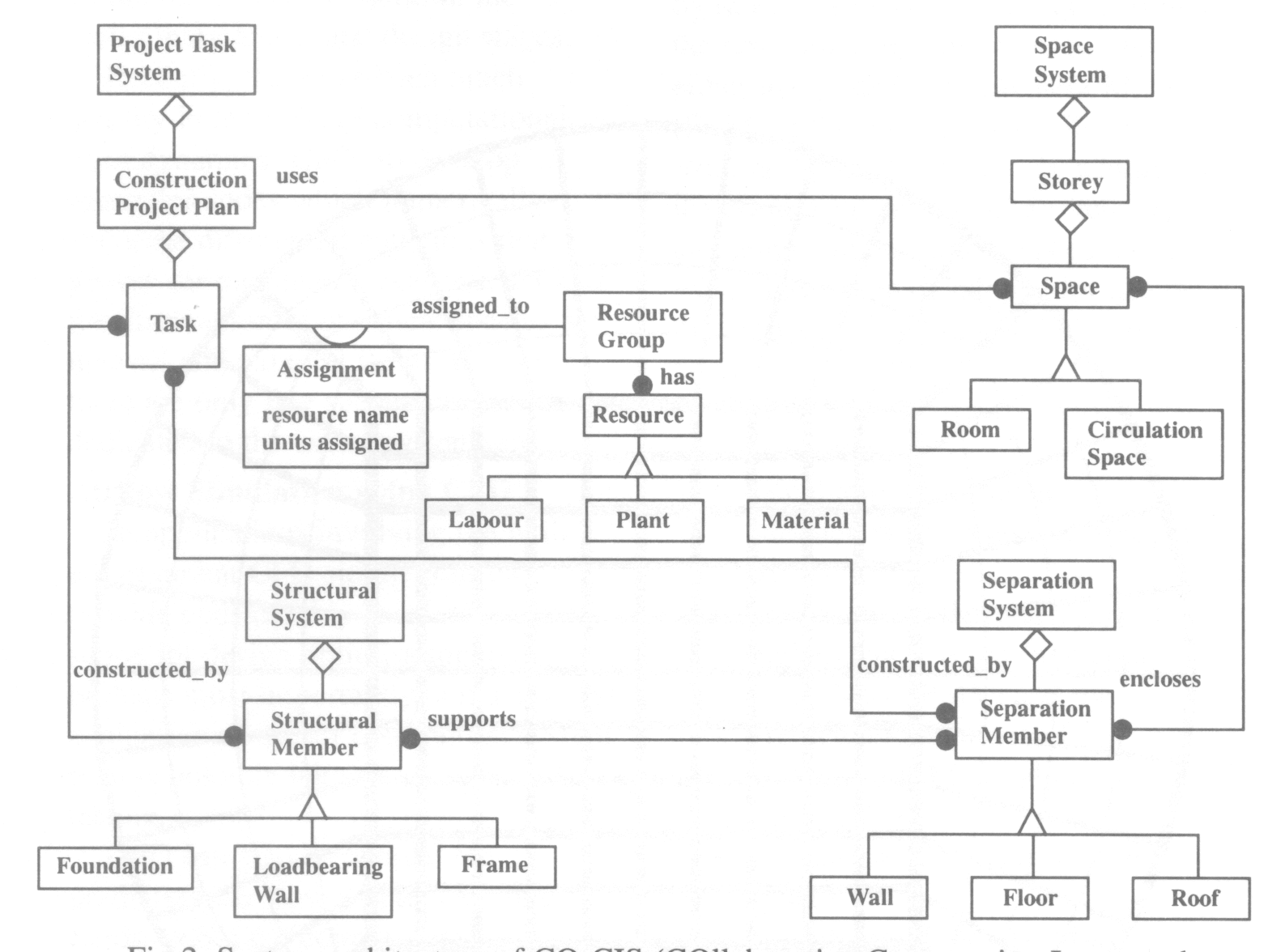
IBPM was initiated as an effort to develop a building product model capable of supporting multiple views of the construction data and be extendible so that more disciplines can be included when it is decided to widen the scope of the model. Primarily, it was concerned with integrating CAD and project planning and control applications. A framework that allows categorisation of data into different levels of abstraction was first established. The Object Modelling Technique (OMT) methodology was used to produce the diagrams. The model was structured around four building sub-systems: Structural System, Space System, Separation System and Project Task.
The Project Task System is used to describe information about the construction and use of the three other spatial systems. The system is structured around the Task (activity) class which represents project planning activities. The Construction Project Plan class contains information about the start and finish of the project, distinguishing between scheduled and actual finish and start times. It describes total hours allocated to resources and project cost information. It also uses data from the Space system for tasks like furnishing, etc. A task is assigned to one or more resources represented as a resource group. It keeps information about duration, preceding and succeeding task and float time. One or more tasks may be needed to construct a structural or a separation member.
The Space System is concerned with describing all spaces in a building mainly from a functional point of view. A space is categorised as either a Room (kitchen, storeroom, office, etc) or Circulation Space (corridor, lift well, etc) but either types can be included to suit different applications. For each space, apart from description information, geometrical and topological information are also in scope. As is depicted in Fig 1, Space has a number of separation (enclosure) elements where a particular separation element can enclose more then one space (many-to-many relationship).
The Separation System is concerned with building objects which are used as vertical (walls) or horizontal (floors, roofs) separators. The function of separation members is to bound spaces. The case of Load-bearing Wall is of special importance. If a wall carries weight then it is part of the Structural System (see next section). However, it can also be used as an enclosure element for a particular space in a building and hence is also part of the Separation Systems. Clearly, the class object Load-bearing Wall must inherit properties from both systems. This is resolved by using multiple inheritance.
The main purpose of the Structural System is to describe data that are related to load distribution. Elements that are in scope include Foundation, Load-bearing Wall and building Frame. For each one of them, different subtypes are included (omitted here). The Structural Members provide support for the Separation Member as shown in Fig 1. The system can easily be extended by adding more sub-types to Structural Member class if needed in particular applications.
An important issue that needs to be addressed within the framework of an integrated system for design and construction is how to facilitate collaboration amongst involved disciplines. A prerequisite towards the effort is to deploy mechanisms capable of retaining knowledge during the projects life-cycle. The utilisation of Intelligent Object Classes (IOCs) can serve this purpose. An IOC gathers information during the progression of the project and makes it available to the involved participants. Starting from design, IOCs accommodate additional data about, for example, how to design or how to construct a particular object. The structure of an IOC contains information about the following:
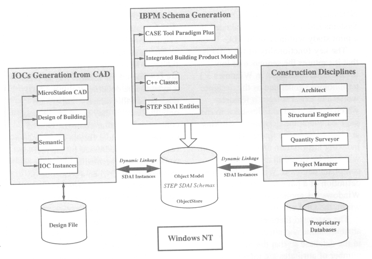
In Fig 2, the system architecture of CO-CIS is presented. The system is aimed at improving collaboration amongst construction disciplines and achieving greater integration of activities. IBPM, which is comprised of IOCs, is the back-bone of the system. The process of building application programming interfaces (APIs) is being enhanced by making the system compliant to STEP SDAI N350. COCIS constitutes three main modules: IOCs generation from CAD, IBPM schema generation and dynamic exchange of objects.
This is the design module where a building drawing is produced by using a front-end add-on application which was developed as part of this project (MicroLink). The designer utilises cell (symbol) libraries to produce the drawing. The users have at their disposal the full MicroStation CAD functionality including 3D solid modelling, rendering, etc. During this process, flat CAD entities are semantically enriched by using an integrated semantic modeller within MicroLink, thus generating instances of IOCs that populate the data-base schemas.
A CASE tool has been used to design the object diagrams that comprise IBPM (Fig 1). By using the code generation options, C++ classes were derived and hand-tailored to meet ObjectStore and SDAI requirements. The compiled schema was then persistently stored in ObjectStore ODBMS.
CO-CIS is designed so that data exchange can take place on-line in realtime. Dissimilar applications, ranging from project planning and control to cost estimating, can dynamically exchange IOC instances by utilising a client/server architecture approach.
The need for effective information sharing within the construction industry requires deployment of state-of-the-art tools and techniques. An advanced object-oriented system architecture, which is the cornerstone of a collaborative environment for construction disciplines (CO-CIS) is the way forward.
Culham Laboratory has a long history of producing simulation codes for modelling plasmas, stimulated by the need to model magnetic confinement experiments, such as JET (the Joint European Torus). As part of the commercial diversification associated with the long-term run-down of fusion research, we began from 1990 onwards to apply our expertise to modelling the plasmas used in high power microwave tubes. In collaboration with tube engineers and our own experimentalists, we have developed the 3DPIC software suite [Eastwood 95] to assist in the design and understanding of these sources.
The most difficult and time consuming part of modelling these devices is the treatment of the plasma, which is represented as a set of (typically collision less) charged particles, moving self-consistently under the influence of the electromagnetic field. The heavy computational cost of pushing particles has motivated the use of a domain decomposition approach in 3DPIC, so that the work can easily be spread across the processors of MIMD computers, such as the Intel Paragon, whilst allowing it to run efficiently on single processor workstations.
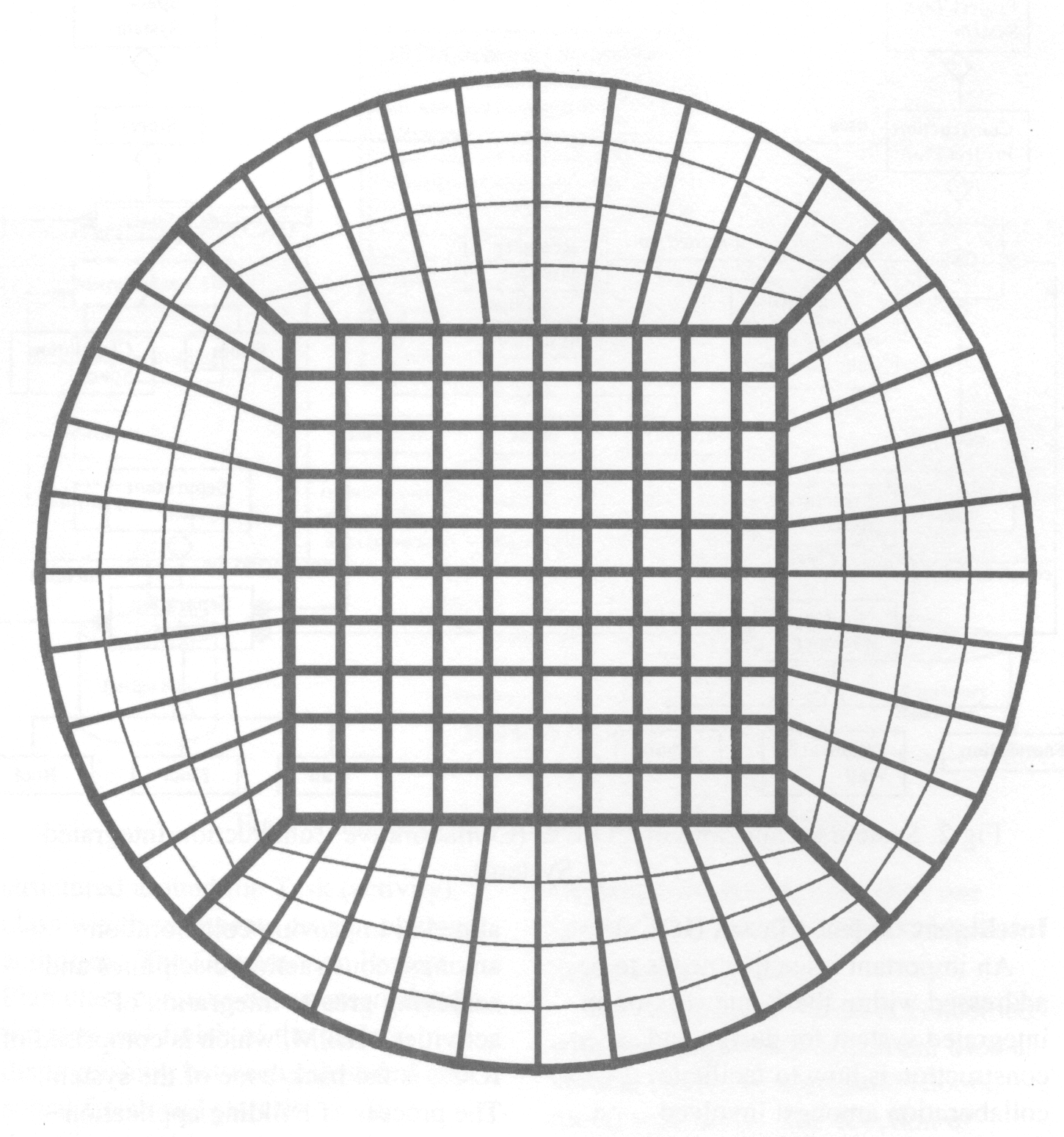
To assist the production of dispersion plots which the engineer demands, the code was designed to work efficiently without particles, in which case it solves the time dependent Maxwell's Equations. Viewed as an electromagnetics code, 3DPIC is of the FETD (finite element, time domain) type. The usual elements are hexahedral bricks extended to be of edge type in time as well as space. The use of a variational principle implies optimality in the resulting discretised system, which is borne out by the fact that in simple cartesian geometry, the algorithm reduces to the well-known Yee scheme. The Yee scheme is known for its superconvergent properties and the absence of spurious modes.
However, we can treat more general geometries as exemplified by the Figure, which shows how a cylindrical cross-section can be meshed so as to avoid a singularity on its axis. We thus have a fast, efficient and reliable method of treating purely electromagnetic problems in complex 2-D and 3-D geometries. It already has interfaces designed for electrical engineers.
We would be interested in collaborations aimed at extending our capabilities in areas where 3DPIC is currently weak, such as absorbing boundary conditions and in some areas of sub-grid modelling (wires, plates etc). We would also be interested in porting it to other MIMD platforms (we currently have versions for the Intel Paragon, IBM SP2 and Meiko CS/2). The particle modelling facilities, which include the ability to treat ion and electron beams, particle emission and multipaction, are available on a commercial basis.
Eastwood J W, Arter W, Brealey N J and Hockney R W Body-fitted Electromagnetic PIC Software for Use on Parallel Computers, Com put Phys Commun 87(1995)155.
Air distribution systems in modern buildings require careful design to meet the increasingly stringent demands for thermal comfort, indoor air quality and energy efficiency.
Although manuals are available for designing conventional air distribution systems, designers have to rely on data obtained from a physical model of the proposed air distribution method when dealing with a non-conventional system. Modifications to the model are then made until the desired conditions are achieved. This procedure is very costly and time consuming. In addition it is not always possible to construct physical models at full scale. Under such circumstances, therefore, a computer based analysis of the room environment would be extremely useful in the preliminary and actual design stages.
Recently, there has been much activity in the field of computational fluid dynamics (CFD) to develop computer codes which numerically solve the differential equations that govern air movement, heat transfer and the distribution of chemical species for internal and external flows. However, there are only few such codes which are dedicated to the built environment.
In applications involving the built environment CFD simulations can provide considerably more detail, more scope for design optimisation and, perhaps most importantly, a much faster evaluation of the air distribution system than is possible with physical model testing.
CFD can also be applied for predicting the flow and temperature fields within the components of environmental plants and systems (eg ducts, flow control components, cooling towers, etc.) to study their performance under different load conditions. This is mainly used for design purposes, system control and performance evaluation of such systems.
In the external environment CFD can be used for simulating the wind flow over buildings and structures. With atmospheric pollution and the environmental impact of certain industrial buildings, tunnels, highways, etc. becoming increasingly important issues, a CFD simulation can provide decision makers, developers and designers with the necessary information in advance of the development stage. CFD is probably the only advanced tool available for designing natural ventilation systems for buildings particularly large enclosures such as auditoria, atria and walk-ways. Unlike scaled building models, CFD is unaffected by the normal scaling problems which are so important in buoyant flows.
In CFD codes, the fundamental flow and energy equations (Navier-Stokes equation) are solved for the whole flow field. The effect of turbulence, which is so significant in the flow inside and outside buildings, is usually considered by most CFD codes. The transport and the turbulence equations are solved either using the Finite Element Method (FEM) or the more popular Finite Volume Method (FVM). In addition to the normal calculation of air velocity and temperature, some CFD codes which have been developed for use in the built environment have additional features such as:
Such codes could be used for a wide range of applications such as:
A three dimensional CFD code called VORTEX (Ventilation Of Rooms with Turbulence and Energy eXchange) has been developed by researchers at the University of Reading for simulating the airflow inside and outside buildings and environmental systems. This code solves the transport equations and the equations for the kinetic energy of turbulence and its dissipation rate using the FVM. The program includes an algorithm for radiation heat exchange within enclosures to enable more accurate assessment of thermal comfort to be made in heated and air conditioned buildings. The PMV and PPD thermal comfort indices are directly computed for the flow field. The program includes other algorithms for simulating fire and smoke spread and pollution dispersion with time. It can also provide detailed assessment of the ventilation efficiency and the age-of-air distribution in an enclosure.
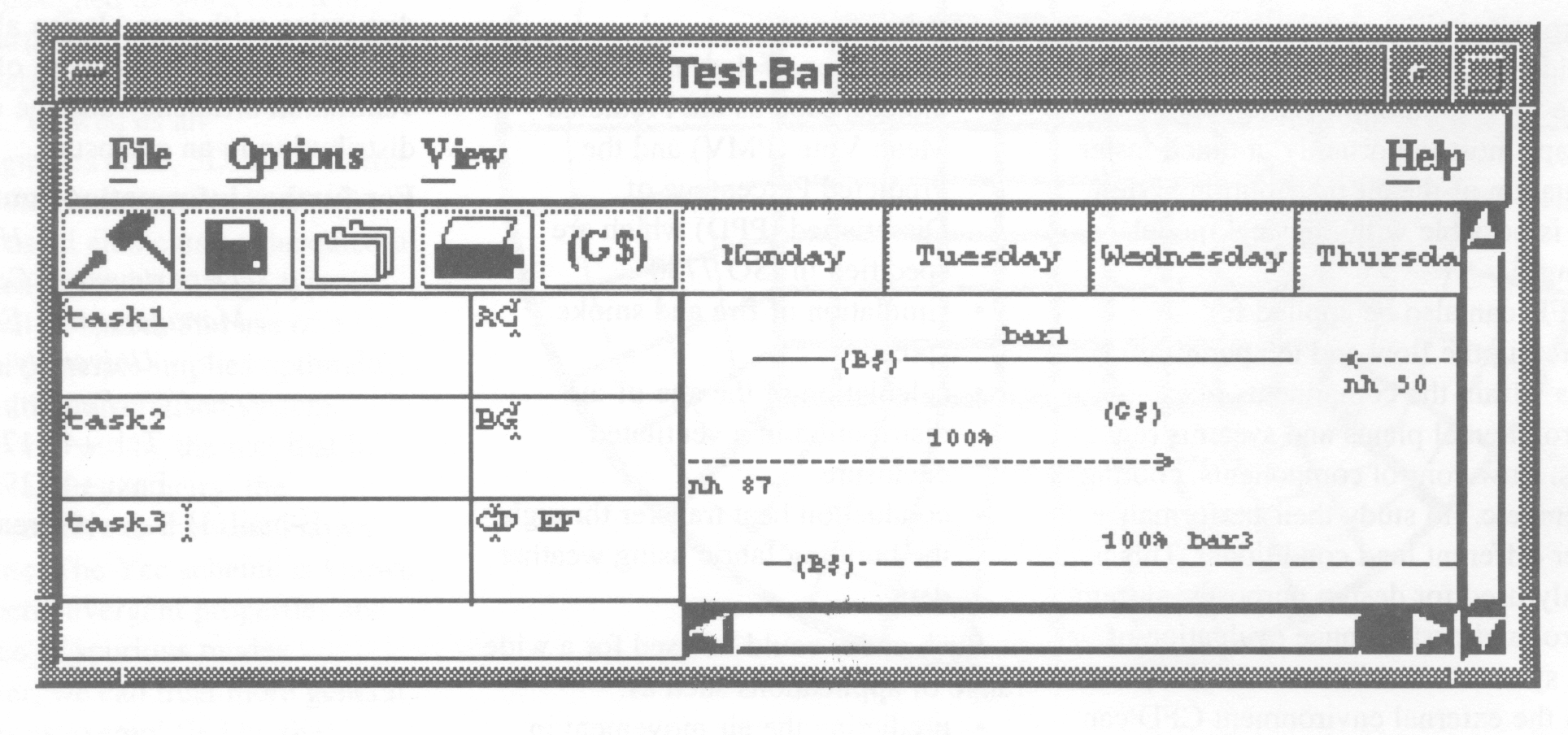
The Time Manager was created to provide a tool which allows users (project managers) to accurately and efficiently keep track of tasks, the time spent on them and by whom. This article describes the tool and the techniques used to implement it.
The program will allow date periods to be placed at the top of the bar chart, in the form of either day, month, year etc. Tasks are placed down the left hand side of the bar chart, which will allow a project to be split into small segments. Each task has a short description and set of default initials. Associated with each task are zero or more bar chart items (this is a line, label, percentage for the default initials, list of initials and percentages for extra people working on the sub-task and list of symbols). Each one of these bar chart items is used to show how much work is done on the task, over a period of time and the initials showing by whom.
The program was designed to replace a manual system that was in operation. The manual system was analysed, and through the use of Object Oriented Design techniques, the system was modelled using Booch notation. This gave the concrete structure that was to be used as the foundation for the implementation. The project was split into two phases: simple and greater functionality.
Phase one of the project was to successfully model a simple version of the manual system, using the Booch notation. Then, after design walk throughs and user discussions to make sure that the model was correct, the design was implemented. The reason that the simple version was produced was to create a good model of the system and thus none of the functionality would be lost from the manual system. The other reasons, of course, were to learn C++ and understand the Motif widget set and the X environment.
The next phase was to take the simple requirements of phase one and expand them so they provided more of what the user wanted. After discussions with the user about the requirements, it was decided to re-model the system and incorporate the new requirements, instead of expanding phase one. The new design was implemented and given to a user to provide feedback. The user gave important feedback on items that should be changed to enhance the programs usability. These were soon implemented resulting in the current program.
The program was implemented on a Solaris 2.3 using X11 R5. It was written using the Motif widget set, and works according to the standard Motif style guide.
Information about the program and how to acquire it can be found at http://www.cis.rl.ac.uk/people/taw/contact.html.
The work was carried out as an industrial placement at the Rutherford Appleton Laboratory forming part of a third year degree from De Montfort University.
When writing software for an embedded controller there can appear to be a problem in deciding whether to use an assembler language or a high level language. The assembler language provides access to all the hardware features of the embedded controller but has a low productivity. The high level language provides a superior software development environment with higher levels of productivity but allows minimal user access to the underlying hardware, as the languages were designed to be platform independent.
The solution is to use a high level language such as C which allows hardware access through the use of library functions, or by manipulating the inherent features of the language to gain indirect access to the hardware. The library functions can be written in the appropriate assembly language and then included during the linking process, once the mechanism for passing parameters to and from the function has been identified. However, unless the speed advantage of using assembly language is an absolute necessity, it is preferred to use C for all the program. The speed-up obtained by using assembly language is approximately 100 over the most efficient C implementation. For example, the maximum square-wave frequency that can be produced by a 33 MHz, 386 PC on an output port with a C program is approximately 50 kHz. With an assembly function called by a C program is approximately 100 kHz.
The main hardware features that have to be accessed in an embedded system are:
Turbo C will be used to illustrate how each of these four features can be simply and easily accessed through the use of supplied library functions.
C already has a mechanism for accessing memory locations through the use of pointers but it does not have a built in mechanism for specifying the address to be accessed. In Turbo C this is achieved through the use of the function:
void far*MK_FP(seg_addr,off_addr);
which enables the segment and offset part of the address required by the PC architecture to be accessed.
/*Example program to access memory. This program looks for the manufacturer's
     code at the beginning of the BIOS. */
#include <stdio.h>
#include <dos.h>
main()
{
 char *pointer;
/* pointer to a character */
 char ch;
 int index;
/* set up the pointer to the start of the BIOS ROM at 0xF000:0x0000 */
pointer = MK_FP(0xF000,0x0000);
/* Read the first 76 characters */
printf("The beginning of the BIOS \n\n");
for (index = I ;index <= 76;index++)
  printf("%c" ,pointer[index]);
/* Wait for a keypress */
 getchar();
 }
Two functions are provided with Turbo C to access I/O ports, one for input and one for output.
 unsigned char inportb(int portid);
 void outportb(int portid, unsigned char value);
and an example of their use is shown below.
#include <stdio.h>
#include <dos.h>
main()
{
 int port_a;
 int input_val;
 port_a = 0x0205;
/*address of port A is 0205H */
 input_val = inportb(port_a);
}
Managing interrupts within C is one of the more complex activities as three separate actions are necessary:
For embedded programs there may be no need to uninstall the interrupt function. However, if the interrupt can be used to indicate different activities at different points in time, then another action is required. An example of a program which installs, activates and removes an interrupt function is given below.
!*Program to test out interrupt vectors from within Turbo C */
#include <dos.h>
void interrupt dummy_int()
{
  /* dummy function */
}
void interrupt (*old_int_addr)();
void interrupt (*new_int_addr)();
main()
(
char ch;
old_int_addr = getvect(10);
printf("\nThe old interrupt vector address is %p \n", old_int_addr);
setvect(10,dummy_int);
new_int_addr = getvect(10);
printf("The new interrupt vector address is %p\n", new _int_addr);
setvect(10,old_int_ddr);
new_int_addr = getvect(10);
printf("Re-instalied interrupt vector address is %p\n", new_int_addr);
getch();
}
The majority of operating systems can be accessed via the operating structure of the microprocessor it has been implemented on, so the use of interrupts outlined above is appropriate. Usually, there is no need to install the interrupt functions as this is undertaken when the operating system is booked up. In addition, to make access to the operating system even easier, the compiler manufacturers will supply suitable library functions. An example of accessing DOS from Turbo C is given below.
#include <stdio.h>
#include <dos.h>
main()
{
union REGS
ip_regs, op_regs, *ipr, *opr;
char msg1[50], msg2[50];
char ans[50];
int index;
printf("\n ");
strcpy(msg1 ,"Hello, my name is Richard, $");
strcpy(msg2,"What is your name?$");
ans[0]=' ';
index = 0;
/* Use DOS to output the two message strings */
(ip_regs.h).ah = 0x09;
/* output DOS service call */ (
ip_regs.x).dx = msg1;
/* First message */
ipr = &ip_regs;
opr = &op_regs;
intdos(ipr,opr);
if (_doserrno > 0)
{
printf("\nThere has been a DOS error.");
getch();
}
(ip_regs.h).ah = 0x09;
(ip_regs.x).dx = msg2;
/* Second message */
intdos(ipr,opr);
if (_doserrno > 0)
{
printf("\nThere has been a DOS error. Second message");
getch();
}
do
{
  (ip_regs.h).ah = 0x00;
  /*input a character */
  intdos(ipr,opr);
  ans[index] = (op_regs.h).al;
  index++;
}
while ((op_regs.h).al != 13);
/* Wait for return * /
index--;
ans[index] = NULL;
printf("\nHello %s",ans);
/*Display name */
getch();
}
The result of the flexibility of the C language is that almost all hardware control can be undertaken directly in C. Only when speed of program execution is a real priority is assembly level programming required.
R C Seals has designed and presented a number of short courses in C programming, aimed at practising engIneers.
The VCC Steering Group met recently with the future strategy for the Club as the main topic of discussion. The result of the EPSRC survey on the of possible future EASE-like activities is now known, (see front page article).
The Steering Group considered the path that the Community Club could take for activities beyond March 1996.
The rapid growth in the PC area was noted. The porting of AVS and PVWave to the ever more powerful PC platform will lead to a new and very large community for visualization. Experience has shown that PC users need a great deal of support, and there may be a need to focus on a small range of products.
New technologies are emerging - VR applied to visualization, multimedia, etc. and the Club would broaden its scope accordingly.
The emphasis would be on training, with the PC and postgraduate markets targeted, and also on conferences and seminars, which have always had a strong inter-disciplinary nature. One of the features of the Visualization Community Club has been its ability to target specific areas.
Two events are planned.
In late January or early February, at RAL: a seminar and demonstrations on New Technology for Visualization, the scope to include 3D, Virtual Reality and AVS Express.
Easter/May possibly, and probably at University of Leeds: a big event - a WWW-based workshop.
All of the masters of the papers presented at last year's Built Environment seminar have now arrived, and we are going ahead with the publication of these proceedings.
This one-day seminar, attended by over 50 people at University of Bristol, provided an opportunity for those working in the development of CFD codes to discuss the important aspect of grid generation. The presentations ranged from grid generation requirements for quite diverse topics, through status of current methodology, to progress in new techniques.
The seminar was chaired by Prof Nigel Weatherill who, as well as successfully introducing the topic, also played a prime role in provoking meaningful discussions around the lectures. In his introduction he explained his understanding of the stages in grid generation and quoted the industry-supported view that it currently took weeks to months for structured grids and days to weeks for unstructured.
There were two lectures which overviewed the methodology (and philosophy!) of the two predominant current approaches to gridding complex geometry: structured/hybrid (Jonathon Shaw, ARA) and unstructured (Joaquim Peiro, Imperial College London). They offered the pros and cons (mainly the pros) of the techniques, and their extensions to generating grids for viscous flow. Making use of an automatic topology approach, it was stated that timescales for structured grid generation were reduced to those comparable with unstructured. Also of note was the comparison between the advancing front and Delaunay methods for generating unstructured grids: the former offers better mesh control whilst the latter is significantly faster. An interesting discussion arose regarding the merits of prismatic elements on the surface, rather than squashed tetrahedra; it is clear that the benefits of one approach over the other have yet to be demonstrated.
It was somewhat disappointing to note that no mention was made in any presentation of the issue of linking grid generation to CAD geometry/packages. Fortunately this was raised in discussion; it was acknowledged that this is an important aspect and possibly warrants its own seminar to which CAD experts should be invited.
Two lectures on quite diverse topics highlighted the demanding requirements put on a grid generation package. Paul Childs (Intera IT) explained the problems of gridding the geological features of oil reservoirs, and Peter Bull (DRA Haslar) similarly presented the difficulties associated with gridding hydrodynamic vehicles. This latter presentation in particular also highlighted the close-coupling between gridding difficulties and demands on the flow algorithm. The awkward geometric areas (rudders, etc) probably requiring unstructured grids are also the areas requiring the best physical models (vorticity, turbulence, etc).
The real need to generate very large models was addressed in the presentation by Paul Selwood (University of Leeds) on the parallelisation of grid generation in adaption. Whilst the belief is that the time saving is important, this is secondary to the potential ability to efficiently generate much larger grids.
The remaining three lectures concentrated on new approaches. A cartesian, body-adapting scheme (Richard Smith, UMIST/BAe), utilising hanging node technology, differed from most approaches in that the surface grid is achieved last, allowing a high level of automation. Flow solutions on several resulting grids, using a commercially available N-S code, showed surprisingly good agreement with experiments. It was interesting to note that the subsequent discussion centred on the validity of the results, rather than the scheme - in contrast to all the other presentations where few (if any) results were shown! The lecture on Neural Networks (Stuart Hartley, Nottingham Trent) was very eloquently presented, but I'm afraid passed well over this reviewer's head; suffice it to say that this is at a very early stage and its applicability has yet to be determined. The final lecture of the day (Clive Allbone, DRA, Farnborough) reviewed the philosophy behind the FAME (Feature Associated Mesh Embedding) method, and provoked lively debate on the merits and potential pitfalls of the approach. He also provoked debate on the appropriateness of various mesh schemes, and finished with a useful summary of his views on what determines a good grid.
The final discussions ranged from the environments around the methods to the need for closer consultation between the code developers. Comparisons were made to the National Grid project in America, though the general view was that good communication already existed here without the need for a more formal set-up.
The overall impression was that the seminar had proved successful. The range and content of the presentations provided sufficient information to generate useful dialogue, both formal and informal, which is where the main benefits are realised from such a gathering. This reviewer was left with the feeling that there was still a tendency for the code developers to only tolerate users, rather than actively understand and address their requirements, but the situation is improving!
Copies of the proceedings from this meeting are available from Virginia Jones.
