
The complete FR80 plotting area has coordinates 0 to 16383 in both directions. Each camera is capable of photographing only part of the plotting area - the aperture plate ensures that plotting outside its bounds is not recorded. However, if output is produced over the complete area allowed by the plate, the images on consecutive frames overlap. Consequently, it is usual to restrict plotting to at least an area such that two consecutive frames abut.
For 16mm and 35mm cine film, the frame area defined in the British Standard is smaller than the abut image with a gap between consecutive frames. The cine image is defined so that on most projectors the outer edges of the image will not be seen. In general, this is preferable to having a blank border around the screen image. However, it may be essential for certain information to be seen. For this reason, a second British Standard image (called cine(projector)) is defined which should be completely visible on all projectors.
For the cine cameras it is, therefore, necessary to measure four areas:
The main image measurements for the hard copy camera are aperture and abutment and these can be done in the same way as for the cine cameras. A cine image with the same aspect ratio as the cine (projector) image is also defined.
It is not possible to abut using the microfiche camera. Consequently, the only measurements necessary are the aperture size and an image size which is defined to avoid overlap.
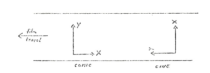
All measurements are made in comic mode on all cameras (x is measured along the film). On the 16mm and 35mm cameras, the camera is mounted off-centre by an amount DX and DY from the centre of the cine image. For the hardcopy camera, the cine image can be defined so that it is not off-centre.
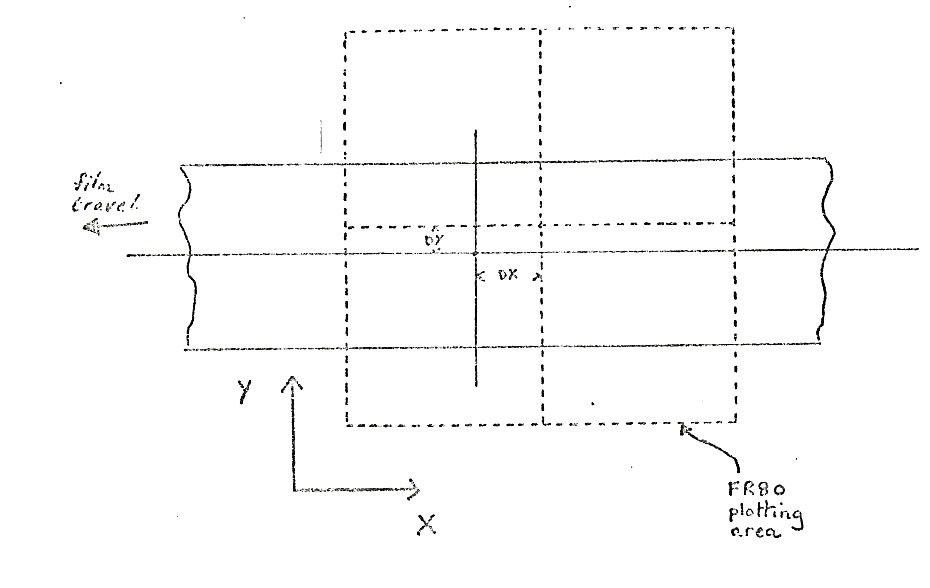
Image sizes for users are given in both cine and comic mode. In cine mode, X is measured across the film.
Cine mode is standard for all cameras other than the microfiche camera.
| Image | XWIDTH | YWIDTH | XMIN | YMIN | XMAX | YMAX |
|---|---|---|---|---|---|---|
| 8020 Combined 35mm | ||||||
| Aperture | 13373 | 16383+ | 1490 | 0 | 14863 | 16383 |
| Abutment | 12510 | 16383+ | 1936 | 0 | 14446 | 16383 |
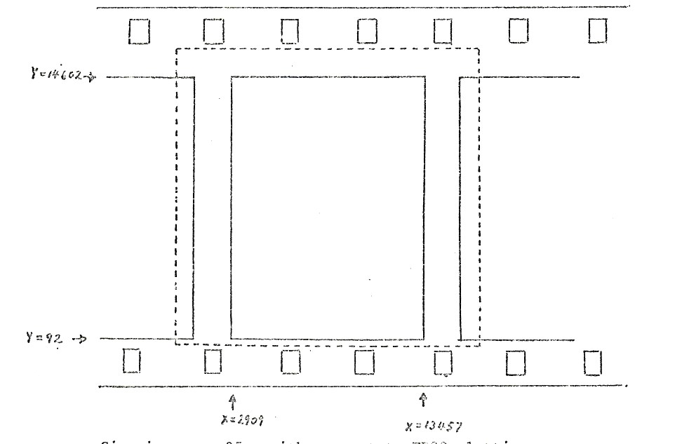
| Cine | 10548 | 14510 | 2909 | 92 | 13457 | 14602 |
| Cine (projector) | 10064 | 13825 | 3151 | 466 | 13215 | 14291 |
Cine image is based on British Standard 0.629 (+.004, -.000) by 0.866 (+.004, -.000) inches
Atlas cine (image) is based on 0.631 by 0.868 both ±.002
Atlas cine (projector) is based on 0.602 by 0.827 (max)
(1 raster = 0.0000598")
The image offset is DX = +8, DY = -8
| Image | XWIDTH | YWIDTH | XMIN | YMIN | XMAX | YMAX |
|---|---|---|---|---|---|---|
| 8020 Combined 16mm | ||||||
| Aperture | 5910 | 7010 | 5220 | 4720 | 11130 | 11730 |
| Abutment | 5000 | 6970 | 5691 | 4740 | 10691 | 11710 |
| Cine | 4906 | 6768 | 5696 | 4832 | 10602 | 11600 |
| Cine (projector) | 4772 | 6399 | 5763 | 5017 | 10535 | 11415 |
Cine image is based on British Standard 0.292 (+.006, -.000) by 0.402 (+.006, -.000) inches
Atlas cine (image) is based on 0.294 by 0.404 both ±.002
Atlas cine (projector) is based on 0.286 by 0.382 (max)
(1 raster = 0.0000598")
The image offset is DX = +42, DY = -25
| Image | XWIDTH | YWIDTH | XMIN | YMIN | XMAX | YMAX |
|---|---|---|---|---|---|---|
| 8021 16mm | ||||||
| Aperture | 8570 | 10180 | 4350 | 3140 | 12920 | 13320 |
| Abutment | 7206 | 10140 | 4588 | 3160 | 11794 | 13300 |
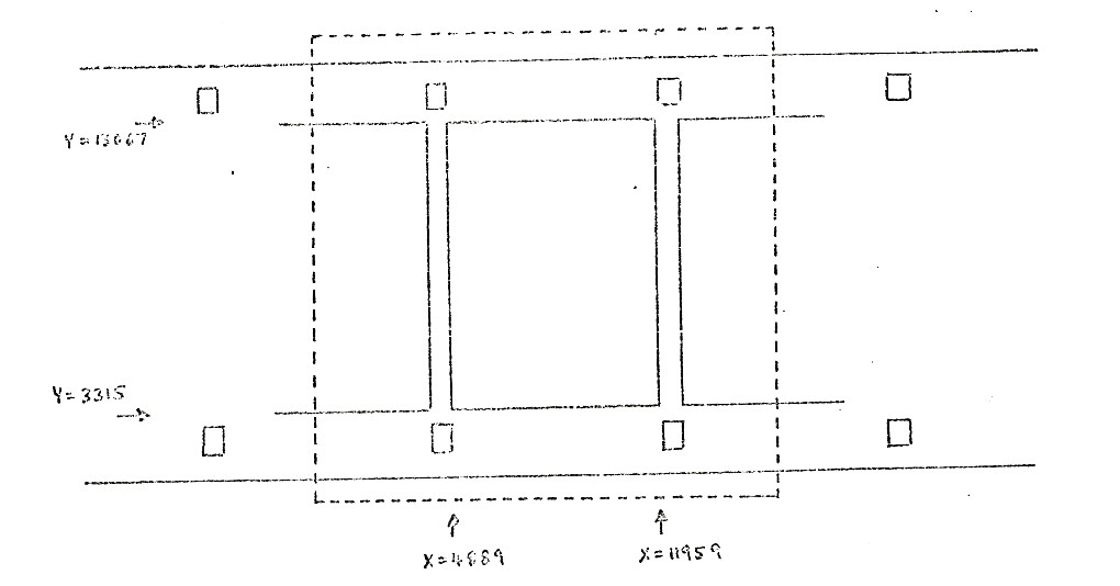
| Cine | 7070 | 9752 | 4889 | 3315 | 11959 | 13067 |
| Cine (projector) | 6828 | 9222 | 5010 | 3580 | 11838 | 12802 |
The image standard for cine are as above.
The image offset is DX = -233, DY = 0
| Image | XWIDTH | YWIDTH | XMIN | YMIN | XMAX | YMAX |
|---|---|---|---|---|---|---|
| 8060 Hardcopy | ||||||
| Aperture | 12905 | 16383+ | 1930 | 0 | 14835 | 16383 |
| Abutment | 12402 | 16383+ | 1990 | 0 | 14392 | 16383 |
| Cine | 12266 | 16383 | 2058 | 0 | 14324 | 16383 |
(1 rater unit = 0.000709")
The cine image defined above has the same aspect ratio as the 16mm cine (projector) image.
| Image | XWIDTH | YWIDTH | XMIN | YMIN | XMAX | YMAX |
|---|---|---|---|---|---|---|
| 8025 105mm Microfiche | ||||||
| Aperture | 16383+ | 16383+ | 0 | 0 | 16383 | 16383 |
| Image | 14400 | 11600 | 992 | 2392 | 15392 | 13992 |
From the measured image sizes it is necessary to produce a set of figures that are of use to package writers and users. These figures should give the coordinates of the four main images in both cine and comic mode. The only adjustment required is to move the abutment image so that it is symmetric about the cine image.
The measured figures for a camera are:
| XMIN | YMIN | XMAX | YMAX | |
|---|---|---|---|---|
| Aperture | xmna | ymna | xmxa | ymxa |
| Abutment | xmnb | ymnb | xmxb | ymxb |
| Cine | xmnc | ymnc | xmxc | ymxc |
| Cine (projector | xmnp | ymnp | xmxp | ymxp |
The offset needed to centre the abutment image is:
dx = ½ (xmnc + xmxc - xmnb - xmxb)
The coordinates of these images in COMIC mode are:
| XMIN | YMIN | XMAX | YMAX | |
|---|---|---|---|---|
| Aperture | xmna | ymna | xmxa | ymxa |
| Abutment | xmnb+dx | ymnb | xmxb+dx | ymxb |
| Cine | xmnc | ymnc | xmxc | ymxc |
| Cine (projector | xmnp | ymnp | xmxp | ymxp |
The coordinates of these images in CINE mode are:
| XMIN | YMIN | XMAX | YMAX | |
|---|---|---|---|---|
| Aperture | ymna | 16383-xmxa | ymxa | 16383-xmna |
| Abutment | ymnb | 16383-xmxb-dx | ymxb | 16383-xmnb-dx |
| Cine | ymnc | 16383-xmxc | ymxc | 16383-xmnc |
| Cine (projector | ymnp | 16383-xmxp | ymxp | 16383-xmnp |
