

Looking back over 1991, the year has been one of relative stability in the Cray and IBM computing services provided by the Atlas Centre. There have been no major installations of new equipment, and although the software systems have moved forward to UNICOS 6 on the Cray and to XA-mode CMS on the IBM, these have been fairly straightforward progressions. Both machines have been heavily loaded with peer reviewed work throughout the year.
In May our first Joint Study Agreement with IBM came to an end. It was marked by a successful seminar addressed by a number of speakers including Mr Alan Howarth, Parliamentary Under Secretary of State at DES. On completion of the Agreement, SERC purchased part of the equipment that had been on loan from IBM. A new Joint Study Agreement with IBM began in June, with emphasis on the use of high performance workstations in cooperation with large machines, an area of great interest given the rapid developments in the performance and functionality of workstations.
The Cray continues to be over-committed. At this time last year I mentioned a proposed new scheme for rationing the available national supercomputing resources according to subject This has now come into effect and is beginning to bite, with the consequence that some grant applicants are being awarded substantially less resource than they have received in the past. In certain cases we are having to place the acceptance of new work on hold until other projects have been completed.
In this context it was good to hear in May that the ABRC was to make available £5M in each of 1992/3 and 1993/4 for enhancements to the national supercomputing facilities. As I write this, it has not been decided how these additional funds are to be used; the new SERC Supercomputing Management Committee is currently formulating proposals for discussion with the Arc's Supercomputing Subcommittee.
Having just had a stable year, I expect that 1992 will see more rapid changes. Technology is advancing fast, and the options for carrying out computational tasks are broadening all the time. Not only are large conventional computers moving forward again after a period of relative stagnation, but massively parallel machines are achieving very high performances in certain applications, and RISC workstations can offer substantial computing power at attractively low costs. New options for data storage and management are opening up, and new types of working are becoming possible across JANET (see also the article in this issue by Roger Evans on a UNIX~ front-end for the Cray). These developments are bound to have some consequences for the kinds of service we provide, and in the coming months we will be looking, in consultation with our users, at the most effective ways forward.
In the meantime I would like to take this opportunity to send seasonal greetings from the Atlas Centre to all our users and suppliers.
Those of you with long memories may remember back to the report produced by Professor John Forty which led to the introduction of the Cray X-MP service at RAL in early 1987. The Forty Report recommended that such a supercomputer should have a variety of front-end machines including IBM, VAX and UNIX. Well, nearly five years later there will finally be a UNIX front-end machine: an IBM RS6000 model 550 is expected to be delivered in December for service in early 1992.
The idea of a UNIX front-end machine when UNICOS already provides an interactive UNIX service itself may seem strange but there are several reasons why a small UNIX front-end machine is beneficial both to you the users and to us in running the Cray service.
If anyone would like to make early use of the RS6000 or has suggestions for graphics software (which must be able to drive X-windows to be of general use) or other application software then please contact either Alan Mayhook (ARM@UK.AC.RL.IB) or me (RGE@UK.AC.RL.IB).
As has been previously announced, the agreement with IBM for the exploitation of the 3090/600E is continuing for another twelve months with a new joint study programme. The theme of this joint study is distributed processing and an invitation to join a small programme of Strategic Users was made in FLAGSHIP 15.
The size of this strategic user programme is much reduced compared with the previous one, partly because only one third of the 600E is covered by the new joint study, and partly because the new theme is expected to require intensive support to develop an area of application programming, which is relatively new to most of us.
At a joint IBM-SERC meeting five strategic user programmes were selected from the high quality responses to the invitation to bid. Four of these were from university groups:
and the fifth is a collaboration with the UK particle physics community (initially on the RAL site) to develop efficient means of coupling their local workstations in to the huge particle physics data banks on the 3090.
Reports on the strategic user programme and other aspects of the joint study will be presented at a seminar at the end of the study period, around the Summer of 1992.
CMS Pipelines is claimed to be the most significant enhancement to CMS since REXX. It introduces into CMS the powerful data flow model of programming which was popularised by UNIX pipes.
A pipeline is built of stages, each stage being a program. The information being processed passes from one stage to the next, being transformed as it goes. Pipeline programs read and write information through a device independent interface. This interface handles the information as a sequential stream of records. This means that for most of the stages of a pipeline it does not matter where the information originated from or where it will eventually go to.
About 100 built-in programs are supplied in CMS Pipelines. A number of these are device drivers which connect the pipeline to host interfaces and which do things like reading a CMS file, reading from a virtual card reader and writing to the console. Many of the other built-in programs are filters which transform the data as it passes through the pipeline (eg COUNT, CHANGE, CHOP). The filters are independent of each other and can be put together in any order. The output from any filter can be connected to the input of any other filter. There are also gateway programs which combine streams of data in various ways (eg FANINANY, OVERLAY).
An example of a simple pipeline is one to count the words in a CMS file and write the answer to the terminal
PIPE < MYFILE DATA | COUNT WORDS | CONSOLE
PIPE commands can be included in REXX EXECs and filters can be written in REXX or assembler to do something which cannot be done by combining the built-in programs. It is also possible to put an often-used group of pipe programs into a subroutine pipeline so that it can be called as a single stage in a pipeline.
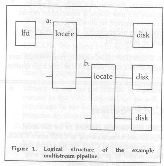
The following example is taken from the CMS Pipelines Tutorial manual. The pipeline is shown in portrait style with one stage per line. This makes it easy to read and allows for comments to be added when it is stored in a file. The diagram shows the logical structure of the pipeline and shows where labels are necessary to identify stages.
lfd is a REXX program which writes one line of information about a file for each file on a minidisk. It uses the LISTFILE command and puts the filetype in positions 10 to 16. The pipeline splits the output from lfd into three streams by selecting on filetype in the locate stages. When the pipeline has been run the file MY EXECS contains a list of files with filetype EXEC, and a heading; the file MY SCRIPTS contains a list for filetype SCRIPT; the file OTHER STUFF contains a list of all other files.
/* Example multistream pipeline */
'PIPE (end \)' ,
    'lfd A|',
    'a:locate 10.5 /EXEC / | ',
    'literal All my EXECs  | ',
    '> MY EXECS A',
 '\a: | ',
    'b:locate 10.7 /SCRIPT/ | ',
    'literal All my SCRIPTs | ',
    '> MY SCRIPTS A',
 '\b:| ',
    'literal All other stuff | ',
    '> OTHER STUFF A'
exit RC
Two papers have been written giving an introduction to CMS Pipelines. Free copies of these can be obtained from the Documentation Officer (MANUALS@RUB).
All these manuals are obtained from IBM. They can be ordered through the Documentation Officer (MANUALS@UK.AC.RLIB).
CMS Pipelines has been installed on a system disk and is available automatically.
The stage separator for CMS Pipelines is vertical bar (hex 4F). This does not look like a bar on some terminals (it may be a broken bar).
If you have any problems please contact User Support.
The FLOW-3D package comprises a suite of programs for the prediction of laminar and turbulent flow in complex geometries. It is supported on a wide range of hardware platforms from small desktop workstations to vector machines such as the Cray. FLOW-3D is mounted on the Cray X-MP/416 at the Atlas Centre, but its use is restricted to those who obtain a licence from CFDS (Computational Fluid Dynamics Service) at the Harwell Laboratory; the purchase may be carried out through the normal grant application mechanism. The program exists as three separate modules: the Grid Generator (GRIDGEN), the Front-end and Flow Solver (FLOW3D) which is highly vectorized for efficient execution on a supercomputer, and the Post Processor (OUTPROC).
Problem solving with FLOW-3D is carried out in the following stages.
In this article the above steps will be described in a little more detail.
FLOW-3D possesses a rich command language in which the user can set up gaseous and fluid flows in complex environments. Keywords are available to allow the specification of many parameters, such as the following:
This is by no means an exhaustive list.
The command language front-end also gives the user a high level of control over the operation of the solver, including the choice of algorithm and convergence criteria. However, sensible defaults are implemented and it is generally unwise to change them unless the solution is causing particular problems. Grid generation at this level is restricted to simple rectangular grids, and it is necessary to use the Grid Generator module (GRIDGEN) for more complex systems. This is described below.
In addition to the command language front-end, there is a means by which more advanced users can specify problems using their own FORTRAN subroutines (the FORTRAN front-end). This facility is available in the current release (2.4), but is scheduled to be withdrawn at release 3 when the vocabulary of the command language will be expanded further.
For complex topologies it is necessary to use the Grid Generation module (although FLOW-3D will accept grids generated from other sources). Grids may be rectangular or body-fitted, and may be specified in Cartesian or cylindrical coordinates, but a principal requirement is that the grid is topologically cuboid (analogous to a mattress which can be deformed but not torn).
This module uses a command language of the same format as FLOW-3D and has constructs to allow the user to incorporate features and obstacles into the flow region. Once the geometry is defined, the grid generator will overlay a grid and perform the necessary fitting to any user-defined features, using a variety of interpolation routines. It is important that the grid be as uniform as possible so some intervention may be required to smooth the grid using one of the more advanced smoothing algorithms.
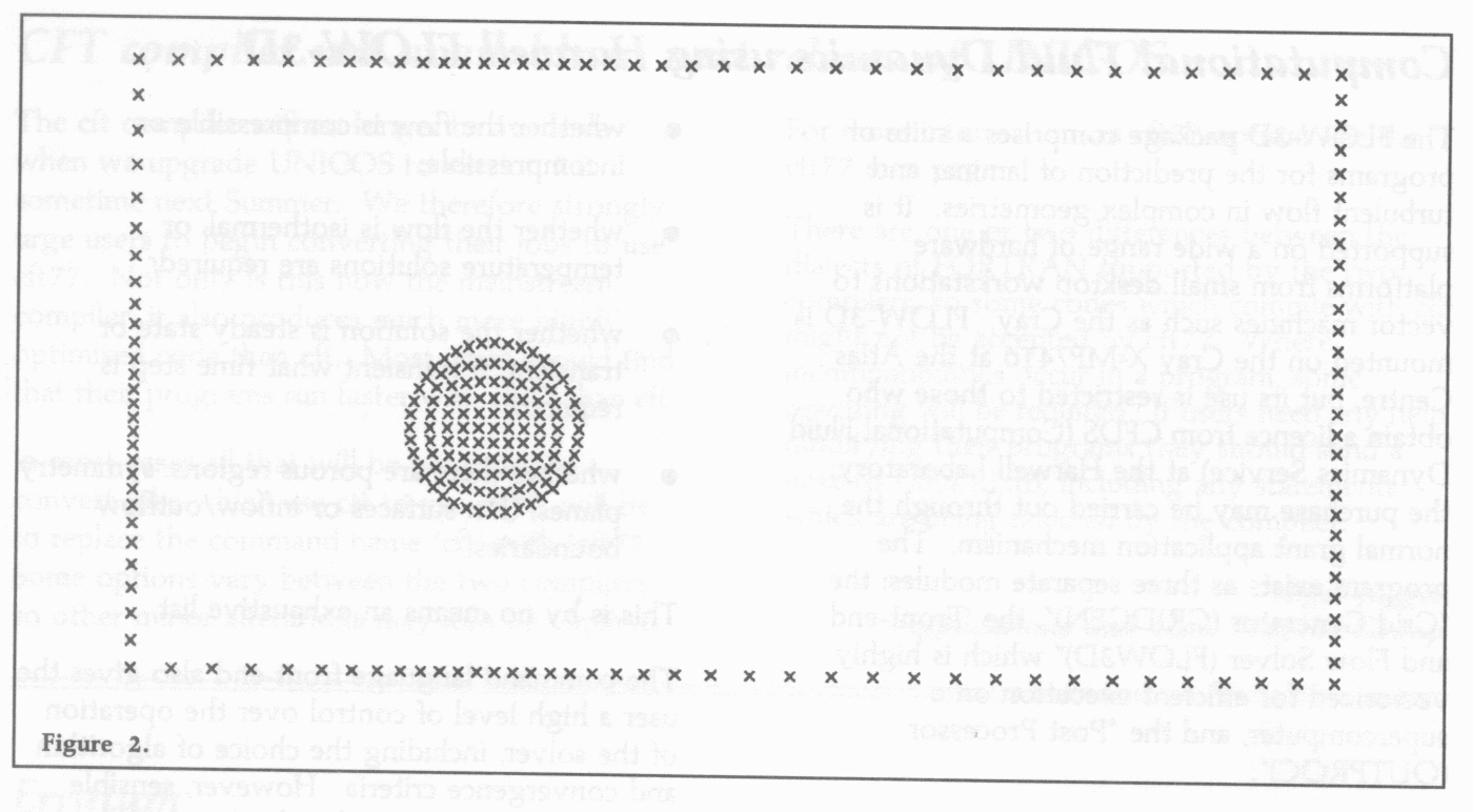
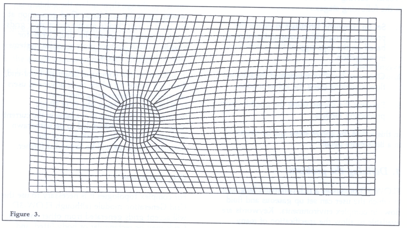
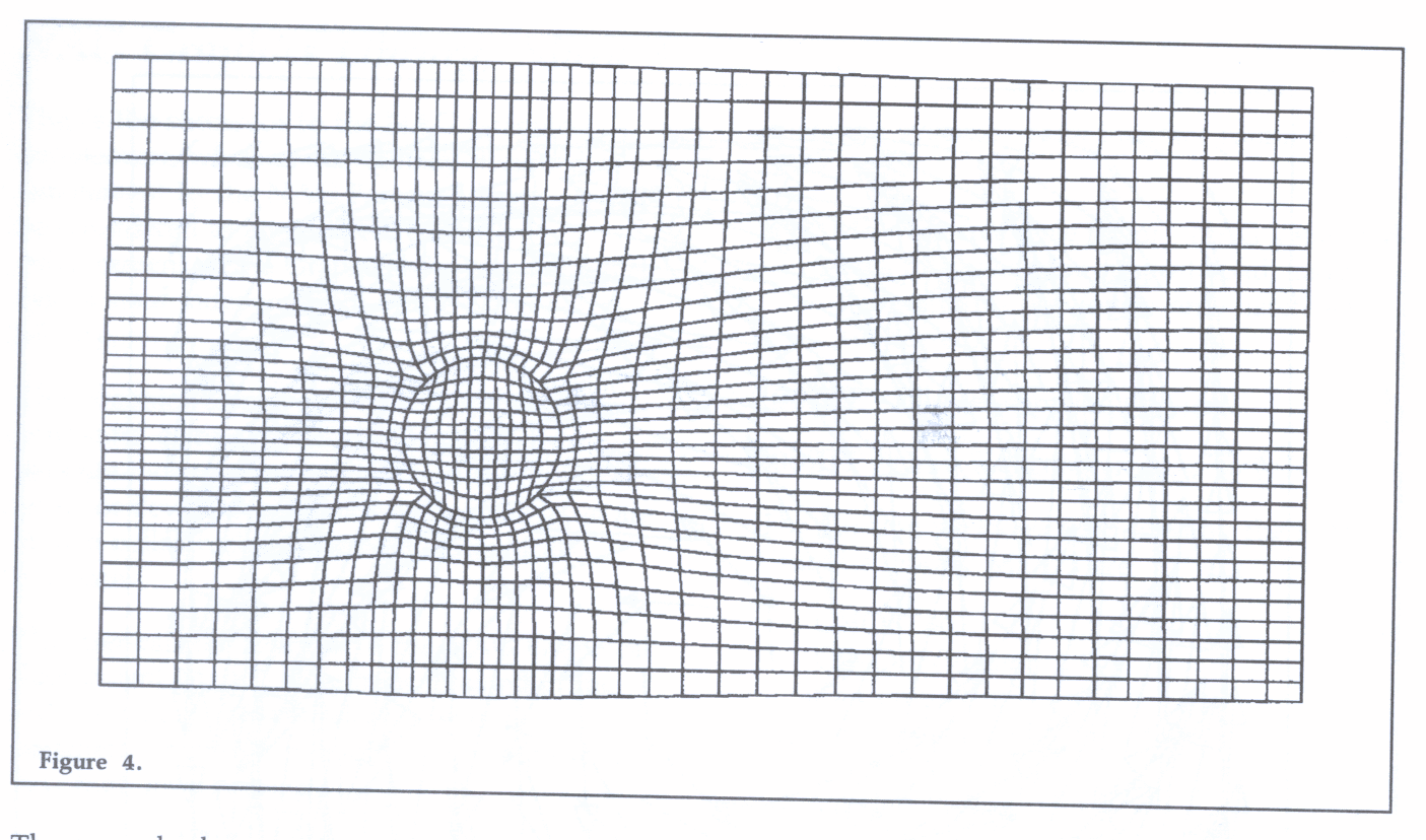
The example shows a rectangular flow region containing a small circular obstruction. Figure 2 on page 10 shows the grid points generated, Figure 3 on page 10 shows the resulting grid using the elliptic smoothing algorithm (note the irregularities in cell sizes around the circle), and Figure 4 shows the final grid after weighted smoothing (achieved by biasing the fit with a point weight placed at the centre of the circle). Grids calculated in this way can subsequently be read into a normal FLOW-3D run.
It is beyond the scope of this article to discuss the solution techniques of the flow equations solved in FLOW-3D, all of which can be carried out without user intervention under normal circumstances. As mentioned above, sensible defaults are set for all aspects of the solver module. The user should only be concerned with deciding what type of fluid flow is present, defining the topology of the flow region, and correctly setting boundary conditions (all of this can be carried out within the command language front-end for most problems).
On successful completion of a FLOW-3D run, several files are produced which contain information for processing by the OUTPROC module. OUTPROC is a batch orientated, finite element post-processor which has to convert all FLOW-3D output into its own internal format before any results can be displayed. The resulting graphics can be produced in a number of formats, however only PostScript output generated from the GHOST graphics library has been tested at present (information on other possible formats is available on request). OUTPROC uses a command language of the same format as FLOW-3D and GRIDGEN and can produce:
amongst others.
Information on licensing arrangements for FLOW-3D can be obtained from Graham Westmacott at Harwell Laboratory
This is the successor to the NAG Graphical Supplement, which was originally designed as a supplement to the NAG Fortran Library. It can be considered as an updated, consistent enhancement of the Graphical Supplement which can be used independently of the NAG Fortran Library.
The Graphics Library can be thought of as consisting of two parts: the high-level or package-independent routines and the low level or device-dependent routines; the latter are known collectively as the NAG Graphical Interface.
The user-callable routines of the NAG Graphical Supplement Mark 2 have been retained in the NAG Graphics Library Mark 3, with no parameter changes. In addition, there are some new high-level routines:
There is a version of the graphical interface for each plotting package supported (e.g. GKS, Adobe PostScript etc). As an appropriate interface is selected at link time, only one version of an application program need be written and maintained, and the resulting code will be highly portable between different machines and operating systems. New interface routines in Mark 3 are:
The plotting packages supported by the NAG Graphics Library Mark 3 are:
CCD support NAG Graphics on DEC machines and on the Cray and IBM mainframes. Please check with local documentation and/or your system manager to find out what interfaces are available on your system.
Documentation for the NAG Graphics Library costs £50 plus £4 for postage and packing, with discounts for five or more copies. RAL staff should contact the Documentation Officer (see back page); others will find it more convenient to obtain it directly from NAG Ltd
The User's Note and the Interface Specific Appendices from it are available on-line with each installation. Extensive on-line help is also provided at the subroutine call level.
Data Compression has been increasingly discussed in the computer press recently. As a technique it has been known about and used for many years, so why the sudden interest in it? This article explains some of the background to two standardization efforts (called JPEG and MPEG) and considers some of the ways in which data compaction may make significant changes to the way we work.
During the last decade there have been many advances in the algorithms for compression of data. There are several reasons for the recent developments. Perhaps the most obvious is the rate at which fax, including group 3 fax compression, has been adopted universally. This only handles on/off representation of an image, but has spread so rapidly that there is hope that an equivalent standard for grey-scale and colour images would also be commercially successful.
A second impetus has come from television, where the desire to be able to transfer video information economically and without loss has been joined by the requirement to transmit high definition television pictures. Whereas a current video frame is conventionally transmitted over a 5.5 MHz channel, a high definition picture (uncompressed) would require a 30 MHz channel. Such channels are not liable to be made available, so compression of successive images is used to squeeze more picture out of the available channel bandwidth.
Finally, computer users are demanding faster changes of the picture on their screens and whether the images come from a local processor or over a network - the only economic solution is for the images to be compressed at source and decompressed as required.
Two expert groups - with considerable overlap in their membership - have been working on suitable standards for image compression. JPEG - the ISO/CCITT Joint Photographic Experts Group - has been working since around 1987 on the compression of still pictures. The details are too involved for this article: interested readers should see reference 1 by Gregory Wallace.
The JPEG proposed standard provides for both loss less coding of pictures and compression of pictures without the ability to reproduce the original image exactly. It uses a "toolkit" approach so that appropriate coding methods may be used and inappropriate ones bypassed. The success of the "lossy" methods may be judged from the following average bits/pixel for moderately complicated full colour images:
Lossless compression usually provides a 2:1 reduction in the data size of an image.
MPEG - the Moving Picture Experts Group _ started work rather later than JPEG and currently has developed a Committee Draft for their standard (the first formal stage of a document). They are addressing the compression of both video and audio, with the aim of achieving real-time video and audio with a bandwidth of 1.5 Mbits/ sec. This is an important figure because it corresponds to available telecommunications data-rates in the US and Europe and to the data-rate that can be obtained with media such as CD and its variants.
Once again the details of the techniques can only adequately be explained in a much longer article and the interested reader should look at reference 2 by Didier Le Gall.
The current MPEG proposal addresses a variety of requirements, including random access and playback in both directions. The proposal is still being developed and some observers expect that there will be a succession of stages of MPEG (as happened with group 1, 2 and 3 fax) until a scale of performance is available for different purposes (as has been achieved for JPEG).
The widespread availability of systems that could decompress JPEG images would provide remote users with three significant benefits:
Considering that at about 0.7 bits/pixel JPEG should provide good to very good quality images and that without JPEG these would probably require around 18 bits/pixel (6 per colour in one of the three colour systems), JPEG is likely to provide compression by about 25:1, or a full 640 × 480 PC screen image in about 27 Kbytes.
RAL are therefore investigating JPEG compression and decompression systems for the many machines and operating systems that we support and will be following the progress of MPEG with great interest.
1. Wallace, G.K. The JPEG Still Picture Compression Standard, CACM April 91, Vol. 34, No.4, pp 31-44.
2. Le Gall, D. A Video Compression Standard for Multimedia Applications CACM April 91, Vol. 34, No.4, pp 47-58.
